
Experiments on an Open-Loop Cycle Carbon Dioxide Refrigeration System
2015-11-24 06:57XuLei徐雷JiangYanlong蒋彦龙ZhengXiaoyi郑小漪CaiYufei蔡玉飞
Xu Lei(徐雷),Jiang Yanlong(蒋彦龙)*,Zheng Xiaoyi(郑小漪),Cai Yufei(蔡玉飞)
College of Aerospace Engineering,Nanjing University of Aeronautics and Astronautics,Nanjing 210016,P.R.China
Experiments on an Open-Loop Cycle Carbon Dioxide Refrigeration System
Xu Lei(徐雷),Jiang Yanlong(蒋彦龙)*,Zheng Xiaoyi(郑小漪),Cai Yufei(蔡玉飞)
College of Aerospace Engineering,Nanjing University of Aeronautics and Astronautics,Nanjing 210016,P.R.China
An open loop cycle carbon dioxide(CO2)refrigeration system is established,and the cooling performances of high-pressure CO2under different storage conditions(25℃,30℃,and 35℃)are investigated.Moreover,the experimental mass flow rates of CO2are compared with the theoretical values at different conditions and refrigeration capacities.The results indicate that the storage condition of CO2has a significant impact on the refrigeration performance,and the mass flow rate of CO2increases with the increasing storage temperature in a given refrigeration capacity.
CO2;open loop cycle refrigeration system;mass flow rate;storage condition
0 Introduction
Nowadays,ozonosphere depletion and the greenhouse effect become serious problems.To reduce these effects,natural refrigerants are promising replacements for chlorofluorocarbon(CFC)and hydrochlorofluorocarbon(HCFC)refrigerants.Carbon dioxide(CO2)is an ideal natural refrigerant thanks to its characteristics,such as safety,non-toxicity,renewability,and environment friendliness[1].In addition,its wide variety of sources and low prices make CO2a good choice for small enclosed spaces like refuge chambers and evacuation chambers.In general,the refrigeration systems for small enclosed spaces can be classified as ice storage refrigeration,electrical storage refrigeration,and high-compressive gas refrigeration.Although ice storage refrigeration is safe,simple,and easy to implement,the system needs auxiliary equipment for ice reservation during normal times,thus leading to high maintenance costs and high energy mass flow rates.In electrical storage refrigeration,it is easy to control temperature and humidity effectively,and the system is mature with low failure rates and low maintenance costs[2].However,the manufacturing costs of explosion-proof batteries are high,and the refrigeration performance is influenced by the external environment[3].
Traditional closed-loop cycle CO2refrigeration systems need active power compressors for operation[4-5].A comparative study of open-cycle and closed-cycle absorption cooling demonstrates that the former has better performance,is less expensive,and uses simpler technology[6].Moreover,in light of recent coal-mine disasters,the no-power open-loop cycle CO2refrigeration could improve equipment reliability.The low cost,high independence,high operating pressure of CO2—which can even be used to drive the pneumatic fan—and the low maintenance costs of CO2storage become the advantages of CO2refrigeration[7].To ensure the reliability of the open-loop cycle CO2refrigeration system and avoid the formation of dry ice,the flow resistance of the long evaporation coils is increased so that the pressure increases after throttling.Furthermore,the refrigeration performance of high-pressure CO2un-der three different storage conditions are investigated,and the influencing factors of the openloop cycle CO2refrigeration system are considered theoretically and experimentally[8].
Cao[9]and Yang[10]studied the refrigeration system performance of the open-loop cycle CO2under different storage conditions.There is a large cooling-capacity loss under the supercritical condition.They addressed the factors influencing the performance in the single throttling system,without any optimization of the design[11].A twostage throttling system without frost has been studied recently,which can raise throttling temperature up to 0℃,and the system is highly adaptable to different temperature and humidity with a shorter length of the evaporator.
1 Theoretical Analysis of Influence of Different Storage Conditions
For the purpose of comparing the cooling performances of subcritical,closed critical,and supercritical open-loop CO2refrigeration systems,the critical temperature of CO2(31.1℃)is considered.Since the CO2cylinders are placed in the equipment compartment,the CO2storage temperature becomes the same as the equipment temperature when reaching the heat balance.The equipment compartment temperature is controlled at 25,30,35℃under the different experimental conditions.After testing the experimental equipment and the measuring instrument,the system is switched on.The following parameters are determined,i.e.,temperature and pressure at the outlet of the high-pressure cylinder,the inlet and outlet of the primary evaporator,and the exhaust outlet.In Fig.1,the cooling process 1—2—3—4 represents the ideal open subcritical loop cycle refrigeration system for 25℃storage temperature,whereas the process 1'—2'—3'—4'represents the ideal open critical system close to the critical point for 30℃storage temperature.Another process 1"—2"—3"—4"represents the ideal open supercritical loop cycle refrigeration system for 35℃storage temperature.

Fig.1 Pressure-enthalpy(p-h)diagrams for openloop cycle CO2refrigeration processes
To meet the design requirements of the coalmine escape capsule,the temperatures of the closed spaces are not over 35℃,which is the critical temperature of the crew compartment. Therefore,the effective operating time period is between the beginning of the experiment and the time when the crew compartment temperature reaches 35℃.For the experiments under the three typical storage conditions,the mass of CO2(M)is known for the effective operating time t. The experimental mass flow rate qeis then given by Eq.(1).

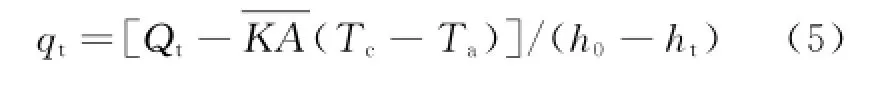
The pressure-enthalpy(p-h)graph of the CO2refrigeration system can be used to calculate the theoretical mass flow rate qtof the CO2cooling process for the experimental crew compartment.

where Qt,Ql,h0,htare the total heat load(2 400 W)of the crew compartment,leakage heat loss of the crew compartment at the storage condition time,initial enthalpy of CO2,and theoretical discharge enthalpy of CO2.
The CO2in the cylinders is in a gas-liquid mixed state,where the gas and liquid are both saturated.At different temperatures and pressures,CO2has different gas-liquid ratios as listed in Table 1.The volume of the CO2cylinder is 40 L,and the net weight of CO2is 18 kg.

Table 1 Gas-liquid ratios of CO2
The processes 1—2,1'—2',and 1"—2"represent the throttling of CO2in the pressure-reducing valve.During the processes,CO2changes from saturated liquid(25℃and 30℃)or supercritical gas(35℃)to the gas-liquid mixed state and the temperature and pressure of CO2are reduced. The processes 2—3,2'—3',and 2"—3"represent the evaporation of CO2,during which it changes from liquid to gas,at constant temperature and pressure.The processes 3—4,3'—4',and 3"—4"represents the heat transfer processes,where CO2is evaporated completely,the pressure of CO2in the evaporator coils is reduced,and the pressure energy is converted to internal energy,thus releasing cold energy.
2 Materials and Method
2.1 Experimental system
Fig.2 shows the experimental system of the open-loop cycle CO2air-conditioning for small enclosed spaces,including an experimental cabin,main refrigeration equipment,and measuring instruments.The experimental cabin comprises the equipment compartment and crew compartment. The equipment compartment holds the CO2highpressure cylinder,and an electric heater is controlled with a solenoid valve to simulate the ambient temperature for the three storage conditions. In order to imitate the structural thermal load and human thermal load on the capsule,the load supply equipment(sufficient bulbs)is installed in the crew compartment.The main refrigeration equipment consists of a CO2compressed cylinder,a pressure-reducing valve,evaporator coils,and a fan for the cooling system[12].The industrial liquid CO2,from the Nanjing Special Gas Limited Company,has 99.8%purity,and the filling coefficient of the standard 40 L CO2cylinder is 0.6. The CO2cylinder is placed in the experimental environment more than 2 h before the CO2experiment to ensure that the temperature satisfies the test requirements.The pressure-reducing valve is of the R12 diaphragm-type from the Hangzhou Baoyan Instrument Limited Company.The evaporators use⊘6 mm(wall thickness is 1 mm)red coppers for three evaporator coils(the diameter of each coil is 1 m),connected as shown in Fig.2. The total length of the evaporator coils is 300 m.
The CO2refrigerant is a consumable substance,discharged from the equipment compartment evaporator coils during the working process.Therefore,it is essential to calculate the CO2refrigerant consumption for the refrigeration design of refuge spaces to meet designed hedging using time.For example,the KJYF-96/12 coalmine mobile escape capsule needs 46 CO2cylinders(70 L)to keep the crew compartment temperature below 35℃and relative humidity under 85%.The measuring instruments include platinum resistances and pressure transmitters for measuring the ambient temperature and pressure of the equipment compartment,outlet temperature and pressure of the CO2compressed gas cylinder,outlet temperature and pressure of the pressure-reducing valve,outlet temperature and pressure of the primary and secondary evaporator coils,as well as external temperature and pressure.The test measuring instruments are listed in Table 2.
The platinum resistance has an accuracy of Grade B,according to the machinery industry standard JB/T 8622.Therefore,the maximum error is the industry maximum error of Grade B:±(0.3+0.005|t|)℃,where|t|is the absolute temperature.The maximum temperature of the experiment does not exceed 50℃,so the maxi-mum error is:0.3+0.005×50=0.55℃,which is 0.55/200=0.275%of the full range.The accuracy of the pressure transmitter is 0.75%,the maximum range 10 MPa,and the error 0.75× 10/100=0.075 MPa.Moreover,the output signal range is 4—20 m A,the transmission accuracy of the current signal 0.01 m A,and the signal conversion error 0.01×10/16=0.006 25 MPa. Therefore,the total error is 0.075+0.006 25= 0.081 25 MPa,which is 0.812 5%of the full range.
The temperature and pressure of CO2released from the high-pressure cylinder are reduced by the pressure-reducing valve,and then the CO2flows through the primary and secondary evaporator coils,where the liquid CO2becomes gaseous and absorbs the heat in the crew compartment[13].Therefore,the open-loop cycle refrigeration system can effectively control the temperature of small enclosed spaces to ensure human health and safety[14].
2.2 Experimental procedure
The experimental procedure is:
(1)The test monitoring system is switched on,and the operation of the platinum resistances and pressure transmitters is checked.
(2)The temperature control equipment of the equipment compartment is switched on,and the equipment compartment temperature(CO2storage temperature)is controlled at 25,30,and 35℃.
(3)The air-circulating fan in the crew compartment is switched on.
(4)The pressure-reducing valve of the cooling system is switched on,and the pressure after the valve is regulated to 3.5 MPa.
(5)The changes in the temperature and pressure of the cooling system are recorded,and the cooling system is switched off when the crew compartment temperature reaches 35℃.
2.3 Uncertainty analysis
From the measured data,the relevant parameters are acquired using the CO2pressureenthalpy diagram.The high-precision pressure transmitter and the thin disk high-precision platinum resistance are used in this experiment.Theplatinum resistance is fixed on the outside surface of the evaporator coils using thermal conductive silicone to improve the measurement accuracy.

Fig.2 Open-loop cycle CO2refrigeration experimental system

Table 2 Test measuring instruments
The initial temperature of CO2in the experiment is an important factor in the calculations. Therefore,in order to ensure its measurement accuracy,the CO2cylinders have to be preserved at the experimental temperature(25,30,35℃)for more than 2 h,with full heat transfer between the CO2and the equipment compartment so that the refrigerant temperature approximates the equipment compartment temperature.However,the external environment causes small-range fluctuations,changing the heat load and crew compartment temperature.
From the accuracy and error calculations for the aforementioned test instruments,the uncertainties of the platinum resistance and pressure transmitter are 0.275%and 0.812 5%,respectively[15].In summary,although small-range deviations exist between the experimental results and theoretical calculations of the cooling performance of the open-loop cycle CO2refrigeration,the results provide theoretical evidence for its engineering application.The detailed calculations and analysis of the experiment are not presented here.
2.3 Experiment for leakage heat loss of crew compartment
Due to the temperature difference between the crew compartment and the external environment,the heat leakage loss of the crew compartment has to be considered for accurately estimating thermal load.The heat load was simulated at 600,1 000,1 200 W,and the temperature of the crew compartment was measured until the external environment and the crew compartment reached an equilibrium.
Considering the last 5 min of the experimental temperature difference between the crew compartment and the external environment,the product of heat transfer coefficient K and heat transfer area A is obtained according to the equation of heat balance.
where Qs,Tbc,and Tbaare the simulated heat load,equilibrium crew compartment temperature,and equilibrium ambient temperature,respectively.
Then,the leakage heat loss of the crew compartment is

where Tcand Taare the crew compartment temperature and the ambient temperature,respectively.
Eqs.(2),(4)can be combined to obtain the following formula
3 Results
3.1 Analysis of factors influencing cooling performance
3.1.1 Effects on cooling performance under different storage conditions
For the storage temperature of 35℃,the temperature and pressure at the key measuring points are shown in Figs.3,4,respectively.It can be seen that from 0 min to 5 min,by adjusting the pressure-reducing valve,the outlet pressure of pressure-reducing valve decreases,and the gas supply temperature and outlet temperatures of the primary evaporator coils and pressure-reducing valve also decrease.From 5 min to 24 min,the gas supply pressure decreases,whereas the outlet pressure of the pressure-reducing valve remains stable.Therefore,their pressure difference decreases.In addition,since the throttling effect weakens during this period,the outlet temperature of the pressure-reducing valve and inlet temperature of the primary evaporator coils increase. From 24 min to 35 min,the reduction in the gas supply pressure is less than that in the outlet pressure of the pressure-reducing valve,so their pressure difference increases.Moreover,the throttling effect is enhanced during this period,so the inlet and outlet temperatures of the primary evaporator and outlet temperature of the pressure-reducing valve decrease.From 35 min to47 min,the difference between the gas supply pressure and the outlet pressure of the pressurereducing valve decreases continually,whereas the inlet and outlet temperatures of the primary evaporator and outlet temperature of the pressure-reducing valve gradually increase.After 47 min,owing to limited CO2and insufficient cooling capacity,the inlet and outlet temperatures of the primary evaporator and outlet temperature of the pressure-reducing valve sharply increase as a result of the increased heat transfer from the crew compartment environment to the evaporator coils.Meanwhile,thanks to the sustained heating of the electric heater controlled by the solenoid valve,the inlet gas temperature of the entire CO2refrigeration system is maintained at about 30℃. Eventually,the exhaust gas temperature becomes larger than the gas supply temperature.This demonstrates that the parameters of the supercritical refrigeration system are non-steady,and therefore the refrigeration capacity loss must be larger than in the critical and subcritical refrigeration systems.

Fig.3 Temperature variation with time for the refrigeration system

Fig.4 Pressure variation with time for the refrigeration system
3.1.2 Comparison of experimental and theoretical mass flow rates of CO2
Fig.5 shows the average temperature of the equipment compartment during the 1 h experimental process.The refrigeration capacity of CO2under a certain condition is limited by the temperature of the equipment compartment.Considering of the unstable flow of CO2,there is a significant fluctuation in the average temperature of the equipment compartment.When the cooling capacity is less than the heating capacity,the crew compartment temperature rises and vice versa.In the end,when the liquid CO2in the cylinder is used up,the cooling effect weakens,and the crew compartment temperature thus gradually increases.For the experiment,the crew compartment temperature of 35℃was taken as the standard to judge the cooling performance of the open-loop cycle CO2refrigeration system at the three different storage temperatures.

Fig.5 Average temperature variation of crew compartment with time at different temperatures of equipment compartment
Table 3 shows the effect of the equipment compartment temperature on the mass flow rate of CO2.It can be seen that the mass flow rate of the CO2refrigerant increases as the equipment compartment temperature increases.Accordingto the pressure-enthalpy diagram of CO2,the initial enthalpy and theoretical discharge enthalpy are influenced by temperature and pressure.It is assumed that the theoretical discharge temperature and theoretical discharge pressure are close to the average ambient temperature and barometric pressure(1.01 bar).The experimental and theoretical mass flow rates of CO2can then be calculated using Eqs.(1),(5),respectively.The mass flow rate of CO2at the equipment compartment temperature of 35℃is much larger than that at 25℃or 30℃,confirming the loss of refrigeration capacity at supercritical throttling. Hence,to decrease the loss of refrigeration capacity and increase the operating rate,the storage temperature of CO2in the equipment compartment should be controlled below 31.1℃.As the high-pressure CO2cylinders are located in the equipment compartment,the storage temperature will become the same as the equipment compartment temperature after a long period of operation.Moreover,the heat transfer of liquid CO2mainly occurs in the crew compartment rather than in the equipment compartment.Therefore, the theoretical discharge temperature is irrelevant to the storage temperature and influences only the crew compartment temperature.Since the equipment compartment has no heat load and the CO2evaporation process absorbs heat from the equipment compartment environment,the storage temperature is lower than the crew compartment temperature.Therefore,the theoretical discharge temperature is higher than the storage temperature.
All the theoretical data are obtained from the pressure-enthalpy diagram and the performance parameters of CO2.It is assumed that the theoretical discharge temperature and theoretical discharge pressure are close to the average ambient temperature and barometric pressure(1.01 bar). Using the pressure-enthalpy diagram of CO2(model),the initial enthalpy can be obtained from the storage temperature and pressure,and the theoretical discharge enthalpy can be obtained from the theoretical discharge temperature and pressure.Then,the experimental and theoretical mass flow rates of CO2can be calculated by Eqs.(1,5).
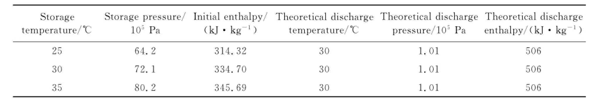
Table 3 Thermal parameters of CO2under different storage conditions
3.2 Leakage heat loss
From the experiment for the leakage heat loss of the crew compartment,the variations in ambient temperature and crew compartment temperature with heating time at 600 W heat quantity are shown in Fig.6.


Fig.6 Variation of ambient temperature of crew compartment with heating time at 600 W

Table 4 KA for different heat quantities of crew compartment
From Eq.(5),with Qt=2 400 W and 49.124 W/℃,the experimental mass flow rates of CO2under different storage conditions are calculated,and the values are compared with theoretical mass flow rates in Table 5.

Table 5 Comparison of experimental and theoretical mass flow rates of CO2
4 Conclusions
An open-loop cycle CO2refrigeration system is tested for a closed space without electrical energy,and the factors influencing its performance are studied experimentally.Based on the experimental data,the theoretical and experimental mass flow rates of CO2are then analyzed and compared.The following conclusions can be drawn:
(1)The theoretical mass flow rate of CO2at the storage temperature of 25℃is closest to the experimental value,indicating that lower storage temperature and larger CO2cooling capacity leads to longer cooling time and higher cooling performance.
(2)When the mass of CO2in the cylinder remains constant,there is a direct relationship between the temperature and pressure of the CO2in the cylinder.The results manifest that the storage conditions(storage temperature)of CO2have significant impact on the refrigeration performance and the mass flow rate of CO2becomes larger as the storage temperature increases.
These results provide a useful reference to the study of the open loop cycle CO2refrigeration system.
The state and distribution of refrigerant of system have been investigated recently,as well as the influence of temperature change.The design of secondary throttle system is optimized experimentally.It provides an important reference to the research and application of the open-loop cycle CO2refrigeration system under the extreme conditions.
Acknowledgement
This work was supported by the Priority Academic Program Development of Jiangsu Higher Education Institutions(PAPD).
[1] Tao Y B,He Y L,Tao W Q,et al.Experimental study on the performance of CO2residential air-conditioning system with an internal heat exchanger[J]. Energy Conversion and Management,2010,51:64-70.
[2] Kim Y M,Favrat D.Energy and exergy analysis of a micro-compressed air energy storage and air cycle heating and cooling system[J].Energy,2010,35(1):213-220.
[3] Chen H S,Cong T N,Yang W,et al.Progress in electrical energy storage system:A critical review[J].Progress in Natural Science,2009,19(3):291-312.
[4] Sarkar J.Review on cycle modifications of transcritical CO2refrigeration and heat pump systems[J]. Advanced Research in Machinical Engineering,2010,1(1):22-29.
[5] Yamaguchi H,Fujima K,Mugabi N,et al.CO2cooling and heating apparatus and method having multiple refrigerating cycle circuits[P].United States:US7,818.971B2,2010.
[6] Hüseyin K,Ziyaddin R,Engin G.Performance analysis of open cycle gas turbines[J].International Journal of Energy Research,2009,33(3):285-294.
[7] Mortaza Y.Performance analysis and optimization of a new two-stage ejector-expansion transcritical CO2refrigerationcycle[J].International Journal of Thermal Sciences,2009,48(10):1997-2005.
[8] Jia X H,Zhang B,Yang B C,et al.Study of a rotary vane expander for the transcritical CO2cycle—PartII:Theoretical modeling[J].HVAC&R Research,2009,15(4):689-709.
[9] Cao Libo.Open mine CO2refrigeration system design simulation and optimization[J].Coal Sci Tech,2013,41(3):96-99.(in Chinese)
[10]Yin Yue,Du Kai,Zhou Ronghui,et al.The feasibility analysis of cooling and dehumidificatioin system in mine rescue cabin[J].Refrigeration,2013,34(5):65-70.(in Chinese)
[11]Yang Junling,Wei Juan,Ma Yuezheng,et al.The applications of stainless steel heat exchanger compartment in mine rescue[J].Coal Sci Tech,2012,37(S2):396-400.(in Chinese)
[12]Cheng L X,Ribatski G,Thome J R.Analysis of supercritical CO2cooling in macro-and micro-channels[J].International Journal of Refrigeration,2008,31(8):1301-1316.
[13]Yamaguchi H,Zhang X R.A novel CO2refrigeration system achieved by CO2solid-gas two-phase fluid and its basic study on system performance[J].International Journal of Refrigeration,2009,32(7):1683-1693.
[14]Hoo K O,Chang H S.Flow boiling heattransfer and pressuredropcharacteristics of CO2in horizontal tube of 4.57-mm inner diameter[J].Applied Thermal Engineering,2011,31(2/3):163-172.
[15]Qiu X J.The detection of experimental equipment for the environmental temperature and uncertainty analysis[J].Science and Technology Innovation Herald,2011,34:48.(in Chinese)
[16]Cai Y F,Jiang Y L,Zhou N Y,et al.Performance of open carbon dioxide refrigeration[J].Journal of Nanjing University of Aeronautics&Astronautics,2011,43(4):551-555.(in Chinese)
(Executive editor:Zhang Tong)
TK12 Document code:A Article ID:1005-1120(2015)04-0452-09
*Corresponding author:Jiang Yanlong,Professor,E-mail:jiang-yanlong@nuaa.edu.cn.
How to cite this article:Xu Lei,Jiang Yanlong,Zheng Xiaoyi.Experiments on an open-loop cycle carbon dioxide refrigeration system[J].Trans.Nanjing U.Aero.Astro.,2015,32(4):452-460.
http://dx.doi.org/10.16356/j.1005-1120.2015.04.452
(Received 17 April 2014;revised 5 July 2014;accepted 10 July 2014)
 Transactions of Nanjing University of Aeronautics and Astronautics2015年4期
- Transactions of Nanjing University of Aeronautics and Astronautics的其它文章
- Control of Vehicle Active Front Steering Based on Active Disturbance Rejection Feedback Controller
- Real-Time Rendering of Dynamic Clouds Using Multi-Resolution Adaptive Grids
- A Hydrodynamic Model for Dimpled Mechanical Gas Seal Considering Interaction Effect
- Resolution Increase and Noise Removal in Particle Size Distribution Measurement with Shifrin Transform
- Perturbation to Noether Symmetries and Adiabatic Invariants for Generalized Birkhoff Systems Based on El-Nabulsi Dynamical Model
- Dynamic Surface Control with Nonlinear Disturbance Observer for Uncertain Flight Dynamic System