
空间超光谱成像仪前置光学系统的热光学特性
2010-05-11 01:39张益茬胡春晖
中国光学 2010年6期
张益茬,刘 伟,胡春晖
空间超光谱成像仪前置光学系统的热光学特性
张益茬1,2,刘 伟1,胡春晖1,2
(1.中国科学院长春光学精密机械与物理研究所,吉林长春130033; 2.中国科学院研究生院,北京100039)
1 Introduction
The spectral imager has shown its excellence performance in remote sensing fields since its first application in 1980s.It has developed rapidly and becomes a hot focus attracting many scientific research groups all over the world in recent years,especially the space hyper spectral imager.The space spectral imager confronts complicated technical difficulties as it must be sent to the earth orbit.Its collimating results in the lab would change after it was sent into the space due to the orbit special environment,vibration of sending,temperature turbulence and the microgravity.After analyzing all of the factors above,the temperature turbulence in the space is regarded as the main problem[1]which arouses much attention.
Temperature turbulence is regarded as the main factor of defocusing and is studied carefully here.In order to ascertain the thermal-optical property[2-4]of the fore optical systemand assess its performance after designing the opto-mechanical system,there is a need to conduct simulating for the system.In this paper,the fore optical systemis simulated and set as an example to demonstrate the common method for engineering application.The presented simulating model is builtvia present practical techniques[5-7]to find the correlation between mirrors′surface deviation and temperature,and the correlation between defocusing amount and temperature,so as to give theoretical reference for the following researching phases.
2 Opto-mechanical system
The hyper spectral imager discussed here consists of several spectrometers and a fore optical system, which is an off-axial reflective telescope system.According to the experiential prediction,a focusing system would be placed on the end part of the telescope.The optical system of the telescope is described by Fig.1.

Fig.1 Schematic diagram of optical system
Fig.1 shows that the fore optical system′s image position directly impacts the imaging quality of the spectrometers.It plays a key role to the imager.
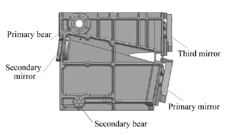
Fig.2 Schematic diagramof main structure
The opto-mechanical system is described by Fig.2.The main structure is a lightened integral casting thin wall body.Three reflective mirrors are placed in the main body by supporting parts.According to the overall design,the focusing mirror can compensate the defocusing caused by thermal elastic deformation.Therefore,it is nottaken into consideration in this analyzing temporarily.However,the main structure,supporting parts and mirrors are laid more emphasis.The key point probed here is the thermal-optical property of the telescope.
3 Thermal-optical model
3.1 Theory and simplification
The thermal elastic deforming model is used to simulate the deformation of mirrors and the image position in response to the temperature turbulence. It derives from thermal elasticity theory[8],which points out that objects would deform if there is uneven temperature distribution on them or there is temperature turbulence existing relative to reference temperature.Stress and strain would exist in the structure of the objects for the same reason given above.Likewise,when there is temperature turbulence in the fore optical system,the stress and strain would generate due to different types of materials and linear expansion parameters of the components in the system.
Based on the theory of thermal elasticity strictly,some assumptions and simplifications are outlined below.
a.All the parts of the telescope system are complete,continuous and homogeneous ideal elastic solid.
b.The displacement and deformation of the system are minute.
c.Simplification of the temperature field:the space hyperspectral imager would work in a complex environment,where the temperature is turbulent during the whole orbit period because of the external radiation and the inner heat.The temperature field is not static but dynamic.However,the temperature changes slightly during the imaging period and the preparation period.So the orbit period could be divided into many short time segments.During each segment,the temperature changes slightly and could be regarded as being static.So the whole system is placed in a succession of static temperature fields, which is flying on the orbit.
d.Uncoupling simplification[8]:when the imager flies on the orbit,temperature difference would result in expansion or shrinkage of the structure, thermal stress and strain.However,the structure would absorb or release heat while expanding or shrinking,which affects the temperature field and changes the distribution of temperature.But the heat is so limited since there is not any intense friction or plastic deformation in the whole system when the systemis operating on the orbit.So the heat deriving from the deformation of the structure could be ignored.The coupled field is simplified into an approximate independent field.
3.2 Constructing finite elements
The telescope consists of main frame,mirrors, supporting parts and joining parts.It is a complex system.So it is unavailable to use a single type finite element to construct the FEM model.Among the overall factors,temperature is the main load of the optical system bears.Therefore,there is no problem with strength usually,but the key point is stiffness of the mechanical structure.The main frame is a thin wall box,which is very complicated with a lot of cross braces and holes.Since the large volume of the frame,the stiffness of the frame is the primary studying item here.After being simplified, the main frame is divided into very small 2D quadrilateral finite elements(about6 mm×6 mm)so as to simulate the real structure and ensure the accuracy of calculation.The constructed grid is not only similar to the real one,but also is able to ensure the harmonious matching of elements′stiffness properties and smooth transition for joining areas in the grid. Athough the shapes of mirrors are very simple,the mirrors are also divided into very small hexahedral elements in order to keep the original mirror surface unchanging and offer enough nodes for surface fitting.And they also guarantees high accuracy of the model.The supporting parts are very complicated, they could not be simplified excessively due to degrading model′s accuracy.They are divided into about10 mm×10 mm×10 mm hexahedral 3D elements.Joining parts of the systemprovide rigid connections in joining areas.They are very important, especially the mirrors′supporting areas.These areas directly affect mirrors′translation and rotation.So those areas are all given special treatment,and MPC (multiple points constrain)is introduced to simulate the special joining areas.There are total 75,968 elements in this model,which contains about 6,000 3D elements and 88 MPC elements.
3.3 Displacement boundary[9]
The imageris fixed by4 axes on the spacecraft. The mounting areas of the main body are free of constrains and can expand or shrink freely.There are only constrains in two pairs of bears in the main frame.One of the primary bears and one of the secondary bears are completely constrained,and the left bears are set free.All the nodes of the constrained primary bear are completely restrained in six freedoms,but only some nodes of the restrained secondary bear are constrained in six freedoms due to the elliptical cross-section.The axis only contacts in the short-axis direction with the secondary bear.So the nodes in the touching areas are placed in six freedoms constraint.
3.4 Temperature load
On the hypothesis of studying thermal-optical property,only the temperature load is taken in consideration but microgravity and other factors are ignored.The reference temperature of the whole system is 18℃,and the temperature would fluctuate between8℃and 28℃ according to the engineering prediction.So discrete temperature loads are distributed between 8℃ and 28℃ in uniform.The temperature fields placed on the model are homogeneous.
The static linear thermal elastic model is built on the MSC.patran software platform via FEM method based on the linear elastic theory.It is shown in Fig.3.

Fig.3 FEM model of the telescope
4 Analysis and Calculation
4.1 Analysis and calculation of thermal elastic deformation[8]
The solution procedure of thermal elastic calculation is similar to common elastic calculation.The only difference is that a temperature load should be added into the physical equation.Being amended, the physical equation is
where Δ T is temperature difference to reference point,αTis thermal expansion parameter.
The thermal elastic FEM equation could be deduced through adding temperature load expression into the common elastic FEMequation.The deduced formula is

where ε0,qe,N,B,D,S represents strain resulted fromtemperature difference,nodal displacement matrix,shape function matrix,geometric matrix,elastic coefficient matrix and stress matrix,respectively. It could be obtained in the following formula by applying virtual work principle on the FEM equation.

where

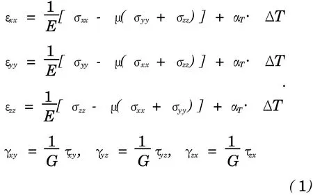
All the nodes of the model stay at the original position when there is no temperature difference. Setting reference temperature,18℃,as a center, apply 8℃,10℃ …… 28℃ temperature fields separately on the model,and solve the FEMfunction on the MSC.patran software platform separately to obtain the nodal displacement matrix,which is the expected results.Since the results are discrete,all the results can be fitted via polynomial expression to obtain the continuous results,which could be regarded as the dynamic thermal response of the model under different temperatures.Where,the deformations of the model under two boundary temperatures are described in the Fig.4-Fig.7.The model′s relsponses to other temperatures are distributed around the center of 18℃ symmetrically.
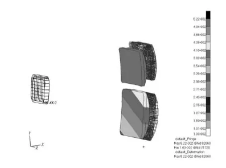
Fig.4 Mirrors′deformation at 8℃(shrinkage)

Fig.5 Mirrors′deformation at 28℃(expansion)

Fig.6 Main structure′s deformation at8℃(shrinkage)
The deformation results show that displacement of the system is minute,belonging to μ m band, which complies with the engineering prediction.Also the results indicate that the mirrors′surface shape and their position both changed due to the expansion or shrinkage resulted from temperature difference. There results approves that temperature turbulence of the orbit is the main reason why the fore optical system defocuses.
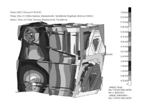
Fig.7 Main structure′s deformation at 28℃(expansion)
4.2 Surface fitting[5-7]
Some nodes′original coordinates and new coordinates after deforming are picked up from the mirrors′surface,and fitted by Zernike polynomial expression.By doing that,the surface deviation(expressed in PV value and RMS value),rotation and offset of the mirrors could be obtained.The approximate correlation between surface deviation and temperature is presented by fitting the discrete surface deviation results.The correlations are shown in the Fig.8-Fig.10.

Fig.8 Correlation between surface deviation and temperature of primary mirror
The curves show that when the temperature rises or drops deviating from the center temperature 18℃,the surface deviation occurs.And the deviation augments while the temperature difference augmenting.However,the deviation does not exceed the limit(PV value≤λ/10,RMS value≤λ/40, λ=632.8 nm)of design due to the mirrors′small volume and material,nucleated glass with very small thermal expansion coefficient,which is only 1× 10⁻⁷/℃.These results coordinate with the engineering prediction and design requirements.

Fig.9 Correlation between surface deviation and temperature of secondary mirror
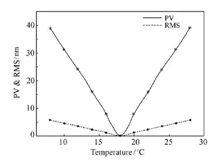
Fig.10 Correlation between surface deviation and temperature of third mirror
4.3 Calculation of defocusing
Some relative coefficients of the zernike polynomial expression and optical systemare extracted and input into the optical design software Code-V.By analyzing in Code-V,the discrete defocusing amounts of the fore optical system under different temperatures are obtained,which are shown in Tab.1.

Tab.1 Defocusing amounts at differenttemperatures(flying direction is negative)
The correlation,which is approximate linear, between temperature T and defocusing amount D could be obtained by fitting the discrete defocusing amounts.And the relation between D and T is
D=10.6267T-192.083, (5) here the relation is demonstrated in Fig.11,and the unit of D is μm.

Fig.11 Correlation between defocusing amount and temperature
According to the application requirements,the opticalsystem′smaximalallowabledefocusing amount is half of a focal depth[10],which could be expressed as

where Δis half focal depth,F is F numberand λis the central wavelength of the spectral range collected by the spectral imager.The fore optical system's half focal depth is
|±Δ|=2×5.542×0.6328 μ m=±38.8 μ m.
Obviously,defocusing amount exceeds the allowable amount when the temperature difference is larger than 4℃,which would make image resolution decreased.Therefore,it is inevitable to adopt the measures to compensate the defocusing in order to guarantee the spectral imager′s high performance.
5 Conclusions
Based on the elasticity,a thermal elastic deforming model for simulating the working statement of the space hyper spectral imager in space environment is built via FEM method.After analysis and calculation,one can obtain some conclusions that
a.The simulation results of the model coincide with the engineering predictions.So the model is authentic and correct in some extents.
b.The results show that the design of the main frame is reasonable since the deformation,rotation and offsetting of the mirror are slight and do not exceed the design limits.The only improvement should be achieved is improving the supporting parts of the secondary mirror,because the secondary mirror rotation around the ray axis is a little large.
c.When there is temperature difference,the image surface would deviate from the focal plane. The image surface would offset from the focal plane in the flying direction of the spacecraft as the temperature decreases,and the maximal offset is 106.9 μ m.Contrarily,when the temperature rises,the image surface would offset to the opposite direction, and the maximal offset is107.4μ m.When the temperature turbulence exceeds 4℃,the defocusing amount runs out of the allowable amount.
d.It is necessary to design a focusing system for the fore opticalsystem to compensate the system′s defocus.When the focusing amount is as-certained,the defocusing amount,errors of the model,the focusing mirror′s rotation and offset resulted from temperature turbulence,and errors of assembly and measure should be considered synthetically.The focusing amount must be greater than the defocusing amount so as to give some allowance.
Acknowledgement:We express our appreciation to all the people who offered help during the research.We specially thank Mr.Liuwei,who supervised the whole research.
[1]王红,韩昌元.温度对航天相机光学系统影响的研究[J].光学技术,2003,29(4):45-47. WANG H,HAN CH Y.Study on the effect applied in space remote camera of temperature[J].Opt.Technique,2003,29 (4):45-47.(in Chinese)
[2]李泽学,吴清文,高明辉,等.超光谱成像仪指向反射镜热光学特性分析[J].红外与激光工程,2008,37(增刊):98-102. LI Z X,WU Q W,GAO M H,et al..Thermal optical property of the pointing mirror in the hyper spectral imager[J].Infrared Laser Eng.,2008,37(supplement):98-102.(in Chinese)
[3]杨怿,张伟,陈时锦.空间望远镜主镜的热光学特性分析[J].光学技术,2006,32(1):144-147. YANG Y,ZHANG W,CHENSH J.Study on the thermal optics property of primary mirror applied on a space telescope [J].Opt.Technique,2006,32(1):144-147.(in Chinese)
[4]吴清文,卢泽生,卢锷,等.空间遥感器中窗口的热光学特性研究[J].光学技术,2001,27(3):260-265. WU Q W,LU Z SH,LU E.Study on the thermal optics property of a window applied on a space remote sensor[J].Opt. Technique,2001,27(3):260-265.(in Chinese)
[5]GERHAED S,DAVID C,GERARD P.Advancements in interated Structural/Thermal/Optical(STOP)analysis of optical systems[J].SPIE,2007,6675:667500.
[6]单宝忠,陈恩涛,卢锷,等.空间光仪光机热集成分析方法[J].光学 精密工程,2001,9(4):377-381. SHANBZH,CHEN ET,LUE.Thermal/structure/optical integrated analysis of space cameras[J].Opt.Precision Eng., 2001,9(4):377-381.(in Chinese)
[7]李福,阮萍,马小龙,等.用Zernike多项式实现光机分析的技术方法[J].应用光学,2007,28(1):38-42. LU F,RUAN P,MA X L,et al..Methods of opto-mechanical analysis with Zernike polynomials[J].J.Appl.Opt.,2007, 28(1):38-42.(in Chinese)
[8]曾攀.有限元分析及应用[M].北京:清华大学出版社,2004. ZENG P.Finite Element Analyzing and Application[M].Beijing:Tsinghua University Press,2004.(in Chinese)
[9]张军强,黄得义,颜昌翔.空间成像光谱仪的主体支撑方式[J].光学 精密工程,2009,17(10):2450-2455. ZHANG JQ,DONG D Y,YAN CH X.Primary support of high resolution space imaging spectrometer[J].Opt.Precision Eng.,2009,17(10):2450-2455.(in Chinese)
[10]王智,张立平,李朝辉,等.传输型立体测绘相机的调焦机构设计[J].光学 精密工程,2009,17(5):1051-1056. WANG ZH,ZHANG L P,LI CH H,et al..Design of focusing mechanism of space tridimensional mapping camera[J]. Opt.Precision Eng.,2009,17(5):1051-1056.(in Chinese)
Thermal-optical property of fore optical systemin space hyper spectral imager
ZHANG Yi-cha1,2,LIU Wei1,HU Chun-hui1,2
(1.Changchun Institute of Optics,Fine Mechanics and Physics, Chinese Academy of Sciences,Changchun 130033,China; 2.Graduate University of Chinese Academy of Sciences,Beijing 100039,China)
The performance of a hyper spectral imager is affected severely by the turbulence of orbit temperature,which would result in the thermal elastic deformation for the fore reflective telescope in the imager.Moreover,the thermal elastic deformation of mirrors,mechanical structure of the telescope,and the resulting displacements of the mirrors would induce defocusing.Based on the present study for a type of space hyper spectral imager,a model for simulating the thermal elastic deformation of the frontal telescope was built via Finite Element Method.By simulating,the surface deviation amounts and displacements of all the mirrors underdifferent temperature loads were worked out,and the correlation between defocusing magnitude and temperature was obtained through calculating the resulting displacements of the mirrors.The analyzing results could be used as a reference fordesigning thermal controlling strategy and focusing system and for doing thermal-optical experiments of the developing imager.
hyper spectral imager;off-axial reflective telescope;thermal-optical property;defocusing amount
分析了空间超光谱成像仪前置光学系统的热光学特性。应用有限元方法建立了模拟前置光学系统的热弹性变形模型,并进行了热弹性分析计算;用Zernike多项式拟合分析结果,求得各镜子反射面在热变形后的面型误差和相对于初始理想位置的偏移;利用光学分析设计软件Code V计算得到光学系统的像面与焦面的偏离量,即离焦量,并用多项式拟合得到其随温度变化的规律。计算结果表明,前置光学系统的像面在温度改变时会偏离焦面,离焦量与温度近似地成线性关系,当温度升高时像面最大偏移量为107.4μ m,温度降低时像面最大偏移量为106.9μ m。该分析结果可作为指导超光谱成像仪改进热控措施,进行调焦补偿的理论参考。
超光谱成像仪;离轴反射望远镜;热光学特性;离焦量
TP73;TH703
A
1674-2915(2010)06-0572-08
2010-05-11;
2010-07-13
国防预研基金资助项目(No.05001SA050)
张益茬(1985—),男,湖南郴州人,硕士研究生,主要从事精密机械及CAD、CAE、CAM方面的研究。E-mail:zhych6998@163.com
刘 伟(1967—),男,吉林长春人,副研究员,主要从事光学遥感仪器方面的研究。E-mail:2400liuWei@163.com
猜你喜欢
中国设备工程(2022年17期)2023-01-02
初中生学习指导·中考版(2022年4期)2022-05-12
中学生数理化(高中版.高考理化)(2021年5期)2021-07-16
中国生殖健康(2020年5期)2021-01-18
空间科学学报(2020年1期)2021-01-14
教书育人(2020年11期)2020-11-26
当代陕西(2020年13期)2020-08-24
中国生殖健康(2018年5期)2018-11-06
中国光学(2015年1期)2015-06-06
中国当代医药(2015年31期)2015-03-01
