
Research on Microcrack Extension Mechanism of SiCp/Al in the Machining Process
2012-07-25 06:21ZHANGZhijun张志军WANGLing王领WANGLibo王利波
Defence Technology 2012年3期
关键词:张志军
ZHANG Zhi-jun(张志军),WANG Ling(王领),WANG Li-bo(王利波)
(Shenyang Ligong University,Shenyang 110168,Liaoning,China)
Introduction
SiCp/Al is a kind of composite material which is combined with aluminum and SiC particles.With several advantages such as light quality,high strength and stiffness,it has been widely used in electronics,aerospace and other fields in the recent years[1].Because of the SiC particles in it,SiCp/Al has a difficult machining process,a poor surface quality and accuracy,a low processing efficiency,and a high processing cost.These problems limit the application scope of the material.
In order to study the cutting deformation mechanism of SiCp/Al material in the machining process and to collect the larger size of cuttings,the author uses the polycrystalline diamond(PCD)cutting tools to do several experiments on a CNC milling machine plan,studies the formation mechanism of the cutting morphology,and then uses the microcrack extension mechanism in the cutting morphology to study the cutting deformation mechanism[2].
1 Cutting Experiments and Cutting Morphology
1.1 Cutting Experiment Conditions
Machine tool:Omar ME650 vertical machining center of which maximum spindle speed is 8 000 r/min and the spindle power is 14 KW.Tool:PCD planer with anterior hornγ0=5°,posterior hornα0=8°,and blade radiusrε=0.4 mm;YDX-III9702 milling dynamometer.The physical and mechanical properties of materials:the volume fractionVfis 56%,the elastic modulus is 220 E/GPa,the flexural strength is 400 f/MPa,the Vickers strength is 200 HV/MPa,and the SiC particle size is 60 μm.The block diagram of experimental set-up is shown in Fig.1,and the experimental diagram of using PCD tool to plane the SiCp/Al material is shown in Fig.2.
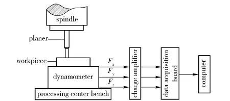
Fig.1 Block diagram of experimental set-up

Fig.2 Experimental diagram of using PCD tool to plane SiCp/Al material
1.2 Appearance Structure Morphology of Cut and Its Original Microstructure

Fig.3 Appearance structure morphology of cuttings
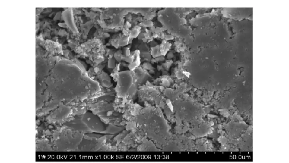
Fig.4 Original microstructure
1.3 Morphology of cut outer surface

Fig.5 Pictures of the morphology of cut outer surface in the cutting condition
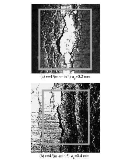
Fig.6 Pictures of the morphology of cut outer surface in the cutting condition
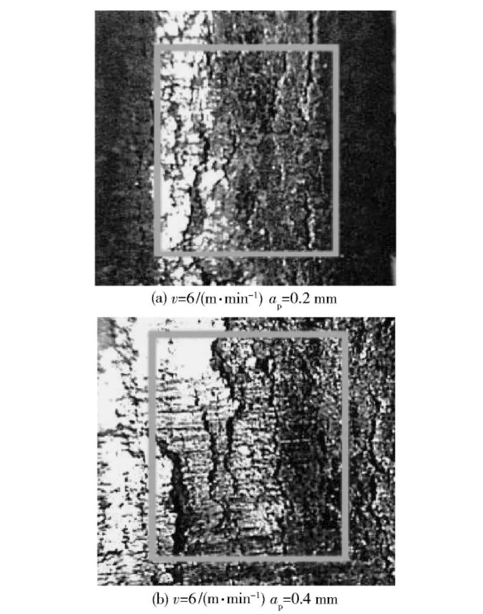
Fig.7 Pictures of the morphology of cut outer surface in the cutting condition
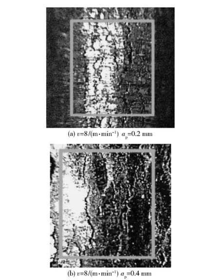
Fig.8 Pictures of the morphology of cut outer surface in the cutting condition
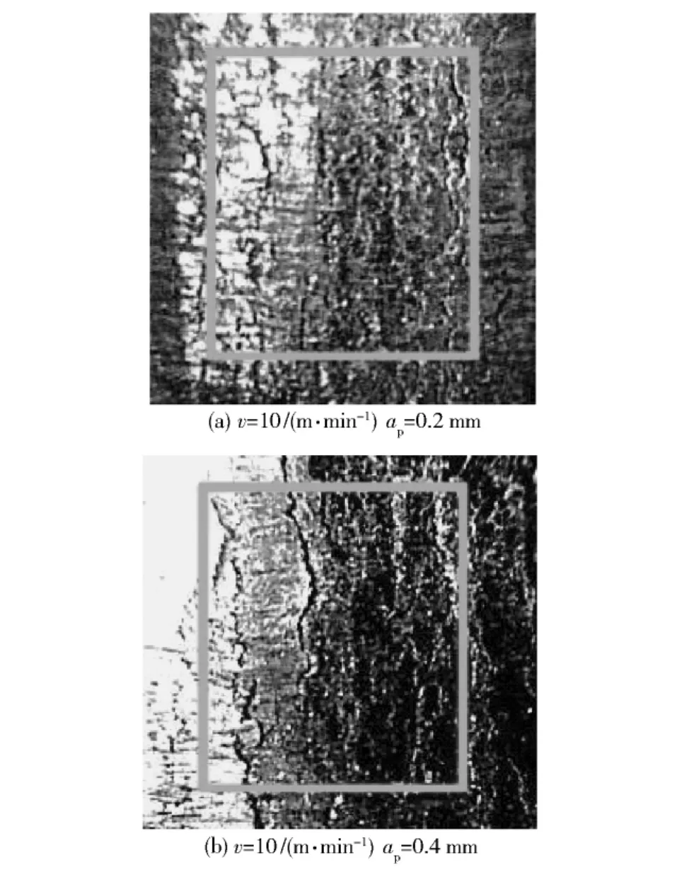
Fig.9 Pictures of the morphology of cut outer surface in the cutting condition
1.4 Structure Morphology of Cut Edge

Fig.10 Pictures of the structure morphology of cut edge

Fig.11 Pictures of the structure morphology of cut edge

Fig.12 Pictures of the structure morphology of cut edge

Fig.13 Pictures of the structure morphology of cut edge

Fig.14 Pictures of the structure morphology of cut edge
1.5 Formulation of Cut Morphology
Figure 3 is the overall appearance of numerous cuttings.It can be seen from Fig.3 that the most of the cuttings are curly,and their curl curvatures are also different.Fig.4 shows the original microstructure of SiCp/Al material.The SiC particles in Fig.4 are uniformly distributed in the aluminum matrix.It is a localized cluster,resulting in diminishing the affinity among the particles.And it is can also be found in Fig.4 that there are serious segregation,hole and microcrack in the microstructure.The binding surface joints of the matrix and the reinforcement are also very clear.
Figure 5~9 show the outer surface morphology of the cuttings at the cutting depths of 0.2 mm and 0.4 mm,and the cutting speeds from 2 m/min to 10 m/min.It can be seen from the figures that much more vertical cracks occur on the cut surfaces.And the larger cracks appear in the middle of the cut surface.Then the vertical folds occur in the vertical direction only on one side.In addition,there are still a large number of turtle-shaped cracks on the cut surface.
Figure 10 to 14 show the morphologies of the cutting both-sides(ie,cut-in side and cut-out side)when the cutting depth isap=0.4 mm and the cutting speed is from 2 m/min to 10 m/min.Two end faces are serrate,the size of cut-in side is small,and the size of cut-out side is large.Besides,the serrate size also decreases with the increase in cutting speed.
2 Changing Mechanism of Microcrack
2.1 Change of Cutting Curl Shape
The cuttings in the Fig.3 are mostly curly,but their curly rates are different.The cutting is ribbon with a larger curvature at a high speed,and is crushed one with a smaller curvature at a low speed.Firstly,the curvature changes with the cutting speed.Secondly,a high cutting speed leads to a high cutting temperature.And thirdly,the increasing cutting temperature leads to an improvement of the thermal stress.At last,the improvement of the thermal stress leads to an improvement of the tensile stress.Above all,the tensile stress leads to a change of the cutting curl.So a small tensile stress results in a high curly rate,and a big tensile stress result in a low curly rate.
2.2 Change of Cut Surface Morphology
There are a large number of microcracks on the cut surfaces in Fig.5 to 9,and the majority of the microcracks are vertical.It means that the microcracks appear in the cutting direction,the larger vertical microcracks appear in the middle of the cutting,and the entire cut surface is covered with moire-like microcracks.
The microcracks occur on the contact surface,and their forms change with the cutting speed[3].Under the role of cutting,the cutting force of metal layer is squeezed by the cut edge,the rake face and the peel cutting inertial force.Because the matrix is flexible and the reinforcement undergoes the larger internal stress,a large number of dislocations have been found.When the speed is lower and the cutting depth is shallower,the microcrack size is larger with the average width of 0.25 mm and the length of 15 mm,as shown in Fig.5 -6.A low cutting speed leads to a low cutting temperature,and due to thinner cutting layer and weak matrix strength,the reinforcement extrudes the reinforcement particles on the matrix under the action of cutting force.The reinforcement particles are brittle and fractured under the role of extrusion pressure,which results to a larger hole which leads to a larger microcrack.In addition,there is severe grain boundary segregation and particle clusters in the microstructure,leading to more shedding of particles.The shedding and breaking of reinforcement particles cyclically produce larger cracks,and these microcrack extension results in a larger crack.Because of a lower cutting temperature at this time,the reinforcement particles are brittle broken,and the cutting is a brittle fracture.Since the stress fields in the enhanced particles are superimposed and the tresses are released,a larger vertical microcrack may occur in the middle of the cutting.
It can be seen from Fig.7 to 9 that the cutting temperature improves with the high cutting speed to make the microcrack extension mechanism change,the large cracks disappear and the tiny cracks increase.Fig.7 shows the transition diagram of the changing microcrack growth mechanism with the average width of 0.18 mm and the length of 8 mm.Matrix is emolliated at the high cutting temperature,the emolliating makes the matrix rheology better,and the reinforcement particles are easier to shed,the cutting transits from brittle fracture to ductile fracture,the microcracks in the expansion of the entire surface tends to be balanced,and the larger vertical microcracks gradually disappear.The cutting temperature increases with the high cutting speed,the matrix flexibly enhances,the shedding of the enhance particles is almost flexible,and the brittle shedding reduces.
The microcracks of the cut surface are smaller and their distribution is more uniform,with the average width being 0.03 mm and the length being 5 mm,as shown in Fig.9.The plastic strain is more concentrated,the uneven thermal expansion makes the reinforcement particles have a high stress in the three directions to hinder the expansion of the vertical microcracks and the extended delay.The microcracks can produce and expanse at the joints of matrix between the hole and the reinforcement,and the entire surface of the cutting is of“turtle text-like”distribution.At this point,the matrix fracture is tough.
The cut surface also shows a‘half’vertical fold in the Fig.5(b)to Fig.9(b),and the size of this fold gradually disappears with the increase in the cutting speed.The sizes of the folds are larger in Fig.6(b)to Fig.7(b),and are very similar in the position of the cross-section except for slight difference in appearance.
From Fig.5(b)and Fig.6(b),it is shown that,in the cutting process,the mutual clearances of the enhance particles are finer due to the arc of tip and the compression of the rake face,the stress field of the matrix between the particles appears to be superimposed to produce a certain deviation stress.This deviation stress is deviated from the lattice positions,but the deviation stress is not able to make the matrix dislocate.Therefore,the folds in Fig.5(b)and Fig.6(b)are not microcracks,and the size of fold depends on the contribution rate of the deviatoric stress.The ‘half’folds appear in the tool feed direction.Due to the lower binding strength of the particles at the other end of the work-piece and the stress superposition of two particles,the large local stress leads to an extension of the partial matrix organization and eliminates the uneven phenomenon of stress.Therefore,there is no fold at the other end of work-piece.Because of the stress field superimposition of the reinforcement particles,the instability of stress and the role of fold produce the microcracks in the vertical direction,and also lead to the larger microcracks in the central cutting.
Some imprints of folds can be seen from Fig.7(b)to Fig.9(b),but the imprints are gradually disappearing.The cutting temperature increases with the increase in the cutting speed,and the increasing temperature promotes a better flexibility of the matrix structure.The flexibility of the matrix structure helps to improve the uniformity of the matrix field stress among the various particles,and the stress uniformity eliminates the fold superposition phenomenon.In Fig.5(a)to Fig.6(a),the uniformity of the particle matrix field stress is good due to the thin cuttings,and the wrinkling phenomenon is not too serious.
2.3 Form Change of Cut Edge
Figure 10(a)to Fig.14(a)show the cut sides.And the cutting morphology shows that the microcrack extension is based on the particle fracture.The cutting temperature is low at a slow cutting speed,and the matrix has a poor mobility.The reinforcement particles oppress the matrix to make it deform,and produce a micro-yield phenomenon.When the whole matrix is bended,the particle fracture causes instability.The deformation of the particles and the substrate tends to the coordination,the flow stress tends to be stabilized,and the morphology of the structure stabilizes with the cutting and deformation.But at this time,the microcrack fracture is a brittle fracture,and the microcrack size is larger.With the increase in the cutting speed,the cutting temperature increases and the flow stress of the matrix increases gradually.At this time,the microcrack fracture should belong to the ductile fracture,and the microcrack size is smaller.
Figure 10(b)to Fig.14(b)show the cut-out sides,and the cutting morphology shows that the microcrack growth is mainly based on the shedding of particles.Because of the faster cooling rate and the lower cutting temperatures at the cut-out side,the microcrack extension mechanism is mainly showed as brittle fracture.When the cutting speed is low,because of the lower cutting temperature,the particles are shed in third or second time,and the saw-tooth size of the cutout side is larger.With the increase in the cutting speed,the cut-out side temperature increases relatively,the rheology of the matrix is gradually changed for the better,the phenomenon of the third or second shedding of the particles become less,and the sawtooth size of the cut-out side is smaller.
3 Cutting Force and Expansion of Microcracks
Figure 15 shows the cutting speed vs the cutting force forap=0.2 mm.It can be seen from Fig.15 that the cutting force is reduced with the increase in the cutting speed.Whenapis smaller and the size of the second phase(reinforcement)is larger,the supporting of the first phase(matrix)and the role of the floor become both wake under the action of cutting force.The carbonation particles are prone to be brittle under the promotion of the cutting force,and the brittle shedding results in a larger cutting force and microcrack size on the cut surface.The microcrack extension mainly causes the brittle shedding of reinforcement at the low cutting temperature and the lower cutting speed.

Fig.15 Cutting speed vs cutting force(ap =0.2 mm)

Fig.16 Cutting speed vs cutting force(ap =0.4mm)
The brittle shedding causes a larger size of the microcracks,and the cutting fracture is brittle fracture.With the increase in the cutting speed,the cutting temperature increases[4],and the matrix rheology changes for better.This makes the enhancement easier to fall off,and the shedding process smoother.The cutting force declines with increase in the cutting temperature,and the cutting force also decreases with the decrease in cutting resistance.The shedding of enhancement is flexible,the microcrack size is small,and the cutting fracture is the ductile fracture.
Figure 16 shows the cutting speed vs the cutting force forap=0.4 mm,in which the change of the cutting force is parabola.The cutting force decreases with the increase in cutting speed,and the cutting force is minimal at 6 m/min.As the speed increases,the cutting force also increases.
When theapand the size of the second phase(reinforcement)are lager,the supporting of the first phase(matrix)and the role of floor are enhanced under the action of cutting force.When the cutting speed is low,the shedding of reinforcement particles also needs a greater force because of the enhancement of the matrix supporting and the floor role.Therefore,the cutting force is much larger than the one with a smallerap.And because of a lower cutting temperature,the flexibility of matrix is not obviously,the shedding of the reinforcement particles is mainly brittle,the cutting is the brittle fracture,and the cutting force is larger.
With the increase in the cutting speed,the cutting temperature increases,the flexibility of matrix is significantly enhanced,the shedding of the reinforcement particles gradually transforms into flexible,the cutting is the brittle fracture,and the cutting force decreases with the further increase in cutting speed,the flexibility of matrix becomes more obviously.The reinforcement particles are surrounded easier under the action of cutting force,and the surrounded enhanced particles are squeezed,which makes the cutting resistance force increase.Now the reinforcement particles have two modes of the flexible shedding and the fracture which are separated from the substrate,and the fracture of the reinforcement particles causes the increase in the cutting force.Because of the flexible shedding of the enhanced particles and the flexible effect of the matrix,the microcracks on the cut surface are decreased.
4 Conclusions
1)When the cutting speed is smaller than 6 m/min,the average width and the length of maximum crack are 0.25 mm and 15 mm,respectively.And when the cutting speed is faster than 6 m/min,its average width is 0.03 mm,and the length is 5 mm.
2)When the cutting speed is smaller than 6 m/min,the cutting fracture is mainly brittle.When the cutting speed is higher than 6 m/min,the fracture is ductile.
3)Because of the superimposition of the stress fields of the reinforcement particles,the instability of stress and the role of fold,the microcracks of vertical direction occur in the center of chip.
4)The fold phenomenon of the chip surface pan is the superposition of stress fields of more than one enhanced particles.
5)The morphology change of cutting edges is similar to the fracture mechanism of chip,but the reinforcement particles at the cut-out side may be shed for two or three times.
[1]QIN Liang,GENG Xiao-liang,GUO Yun-qiang.The progress of the study of SiCp/Al mechanical behavior[J].Aeronautical Manufacturing Technology,2010,16(364):80 -82.(in Chinese)
[2]QUAN Yan-ming.The chip formation mechanism of the hard and brittle particle reinforced metal matrix composites[J].Journal of South China University of Technology(Natural Science),1998,26(8):27-30.(in Chinese)
[3]YE Bang-yan,LIU Wei,XU Jin,et al.The surface roughness and tool design of the particle reinforced composite materials[J].Tool Technology,2004,38(9):99-102.(in Chinese)
[4]LIU Dong,CHEN Wu-yi.The study of the cutting force and cutting temperature in turning of silicon aluminum alloy[J].Non-ferrous Metals,2006,58(1):39 - 41.(in Chinese)
猜你喜欢
中国典型病例大全(2022年12期)2022-05-13
故事会(2020年10期)2020-05-19
法人(2018年3期)2018-04-24
初中生世界·九年级(2016年4期)2016-04-21
共产党员·下(2014年6期)2014-08-06
共产党员(辽宁)(2014年12期)2014-01-18

- Defence Technology的其它文章
- An Investigation on a Tin Fixed Abrasive Polishing Pad with Phyllotactic Pattern for Polishing Wafer
- An Approximate Calculation Method for Lateral Trajectory Correction
- Lift Enhancement and Oscillatory Suppression of Vortex-induced Vibration in Shear Flow by Loentz Force
- A Study on Criteria for Barrel Lifetime
- Molecular Dynamic Simulation for HMX/NTO Supramolecular Explosive
- Monitoring Method for the Electrical Properties of Piezoelectric Transducer