
MATHEMATICAL MODEL OF 4He QUANTUM INTERFEROMETER GYROSCOPE
2012-10-08 12:10ZhengRuiZhaoWeiLiuJianyeXieZhengFengMingyu
Zheng Rui,Zhao Wei,Liu Jianye,Xie Zheng,Feng Mingyu
(1.Navigation Research Center,Nanjing University of Aeronautics and Astronautics,Nanjing,210016,P.R.China;2.College of Electrical Engineering and Information,Anhui University of Technology,Maanshan,243002,P.R.China)
INTRODUCTION
Superfluid4He has the character of quantization and no viscosity. Based on the phenomena of4He passing through the very small apertures,rotation can be detected.This device can be called superfluid gyroscope which has a very high sensitivity.Based on the principle of phase slip[1], Saclay Research Centre and University of Pairs-Sud[2-3]detected the rotation of the earth firstly when the superfluid passed through an aperture.The similar detection was accomplished by the researchers of University of California,Berkeley[4-5].But sensitivity of phase slip gyroscopeis limited by thermal noise[6].The4He quantum interferometer gyroscope,which is based on the principle of Josephson effect when superfluid passing through the weak link[7],is less affected by thermal noise than the phase slip gyroscope. Some foundational researches have been done in University of California,Berkeley[8-9]and University of Harvard[10].Russian Academy of Sciences used this gyroscope to measure the gravimagnetic effect[11-12].Though gyroscopic effect has been detected from experiments,these gyroscopes are still far away from applying to common inertial navigation systems.The Navigation Research Center(NRC)of Nanjing University of Aeronautics and Astronautics focuses on the application of superfluid gyroscope in recent years.Some work about performance analysis and dynamic range expansion has been done[13].
However,in the preceding researches that focused on the experiment,system model was not given in detail.In this paper,the mathematical model of4He quantum interferometer gyroscopeis deduced.Simulations based on the experimental parameters[9,14]arealso presented.Themodel that includes driven equation,current equation and position equation can describe this gyroscope sufficiently.
1 GENERAL PRINCIPLES OF SUPERFLUID
Stableisotopes of4He undergo the superfluid phase transition at low temperature(2.17 K)[15].Below the transition temperature the liquid can exhibit current without any dissipation. In London′s two-fluid model, there are two components in liquid4He.Oneis the normal fluid component and the other is the superfluid component.If d s and d n represent the density of superfluid and normal fluid fraction respectively,d represents the total density of liquid4He,shown as

The superfluid fraction can be described by a macroscopic quantum-mechanical wave function,that is

where h is the complex phase,and the gradient of phase is related to the superfluid velocity v s,shown as

where h is the Planck′s constant,and m4 the mass of a4He atom.
To assure the single valuedness of the wave function,if the function is integrated around any closed path lying in the fluid,the total phase change must be an integral multiple of 2π,that is

Thus combining the result with Eq.(3)leads to the current restriction condition,that is

whereκ4=h/m4.
2 PRINCIPLE OF 4 He QUANTUM INTERFEROMETER GYROSCOPE
Superfluid4He interferometer gyroscope schematic and equivalent circuit are shown in Fig.1[9].In Fig.1(a),the unshaded regions are filled with superfluid4He.In Fig.1(b),the positions of’×’are two weak links.The weak links and the diaphragm compose the inner cell,and the others compose the outer cell.Electrostatic force that can pull up diaphragm can be used by applying voltagebe tween electrode and diaphragm, thus pressure differenceΔP is established between the inner and the outer cells.The resistor R is a heater that can contribute temperature differenceΔT between the inner and the outer cells. Above the electrode is a superconducting pancake coil(not shown)which is part of a superconductivity quantum interference device(SQUID)-based sensor used to detect the motion of the diaphragm.

Fig.1 Superfluid 4 Heinterferometer gyroscope schematic and equivalent circuit
The difference of chemical potentialΔ_between the inner and the outer cells is determined byΔP andΔT[6],that is

where s is the entropy per unit mass.IfΔ_≠ 0,the superfluid fraction occurs the Josephson oscillation at the weak links,then two mass waves I1 and I2 are formed.From DC Josephson equation,we can obtain I1=I c sin(Δh1)and I2=Icsin(Δh2),where Icis the critical superfluid mass current in weak link,Δh1 andΔh2 are the phase difference of superfluid between the two weak links.In Fig.1(b),the total current I t=I1+ I2.If the gyroscope is rotating with angular velocity vectorΩ,using Eqs.(3-4)can deduce I t=2I c|cos(2πΩ◦ A/k4)|◦ sin((Δh1+ Δh2)/2),where A is the sense area vector of the loop.From AC Josephson equation dΔh/d t=- 2πΔ_/h,and keepingΔ_constant,we have

where 2Ω◦ A/κ4 is the rotation flux,f J= Δ_/h the Josephson frequency. From Eq.(7),the rotation flux is modulated to the amplitude of I t.Using SQUID that is set above the electrode,the current through weak links can bedetected.Thus the rotation flux can be detected by4He quantum interferometer gyroscope.
The principle of superfluid gyroscope to detect rotation is based on the Josephson effect which occurs at weak links.Therefore,Δ_must exist firstly.In order to ensure the stability of mass wave,Δ_should be kept constant,then f J is constant.From Eq.(6),there are two ways to driveΔ_,i.e.pressure drive and thermal drive.
3 MATHEMATIC MODEL OF PRESSURE DRIVE
In Fig.1,resistor is not applied.Applying electrostatic force to establish the pressure difference,Eq.(6)can be expressed asΔ_=m4ΔP/d.This way is called the pressure drive.
Electrostatic force Fewhich can pull on the diaphragm is applied between electrode and diaphragm,shown in Fig.2.From the Newton′s second law,we have
Fe(t)= ΔPAm+ KΔx(t)+ m4(d2x/d t2)(8)where Am is the area of diaphragm,k the Hooke coefficient of diaphragm,andΔx the displacement of diaphragm from its equalized position.
In order to keepΔ_constant,ΔP must be constant,so F e should be adjusted according to Eq.(8).
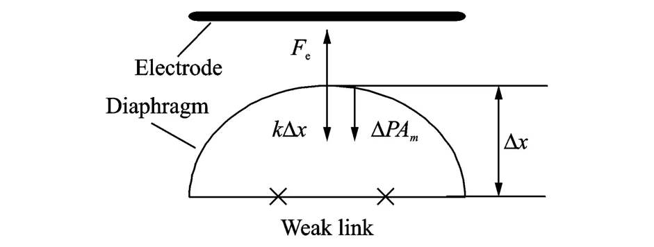
Fig.2 Force in diaphragm of pressure drive
Simulation parameters are selected as:Velocity of diaph ragm is 10-9m/s,the maximum displacement of diaphragm is 10-8m.Keeping d2x/d t2=0,ΔP=0.01 Pa,Am=5× 10⁻⁵m2,and k=9.9×10³N/m, simulation curves of electrostatic force and Josephson frequency in pressure drive are shown in Figs.3-4.

Fig.3 Electrostatic force in pressure drive

Fig.4 Josephson frequency in pressure drive
From Fig.3,F e linearly increases within 0—100 s. Then the displacement of diaphragm reaches its maximum value at 100 s. IfΔP continues to keep constant,the displacement of diaphragm will exceed its maximum value.Therefore,F e cannot be adjusted by Eq.(8).From Fig.4, Josephson frequency f J keeps constant near 700 Hz within 0—100 s,and after 100 s f J will lose constancy. Therefore,if pressure drive is used,the gyroscope can only work for a short time(in this case about 100 s).
From the above analysis,in the pressure driven system, there are two motions of superfluid4He. The one is the DC current I dc which is caused by the adjustment of electrostatic force,and the other is ACcurrent which is caused by the Josephson oscillation,then the total mass current of pressure drive is I(t)=I dc(t)+ I ac(t).If I dc(t)is constant,from Eq.(7),we have


Then the displacement of diaphragmΔx is where U=1/d Am is the coefficient that converts the mass of current to the displacement of diaphragm.Eqs.(8-10)are the driven,current and position equations of pressure drive.
Simulation parameters are selected as:f J=700 Hz,U I ac=5.2×10⁻¹⁰m/s,U I dc=10-10m/s.When the rotation flux is zero,the displacement of diaphragm within 5—5.05 s is shown in Fig.5.

Fig.5 Displacement of diaphragm in pressure drive(rotation flux is zero)
From Fig.5(a), the displacement of diaphragm caused by DC current linearly increases at constant pressure.From Fig.5(b),the displacement of diaph ragm caused by AC current oscillates at Josephson frequency.The amplitude of this oscillation shows the value of rotation flux.From Fig.5(c),the displacement of diaphragm caused by total current increases gradually.
When the rotation flux is 0.4,it decelerates from 0.4 to 0.2 within 5.01—5.03 s,and then it keeps 0.2. The displacement of diaphragm is shown in Fig.6.
In Fig.6(a),when rotation flux is 0.4,its amplitude is constant;in the decelerated process of rotation flux,its amplitude is changed;when rotation flux is 0.2,its amplitudeis constant and is bigger than that when rotation flux is 0.4.From Fig.6(b),the displacement of diaphragm caused by total current gradually increases.
4 MATHEMATIC MODEL OF THERMAL DRIVE

Fig.6 Displacement of diaphragm in pressure drive(rotation flux is varied)
In Fig.1,the electrostatic force is not used,and resistor R is used to heat theinner cell.This way is called the thermal drive.The current,pressure and temperature of inner cell in thermal drive is shown in Fig.7.When the heater is applied,the temperature of the inner cell begins to rise,thus creating a temperaturedifferenceΔT across weak link.Because of thermo-mechanical effect,the net current I s(net)of superfluid comes into theinner cell causing pressureΔP to be built up.ThisΔP is different from ΔP in Section 3 which is caused by the electrostatic force.The normal fraction I n of liquid4He comes out of the inner cell caused byΔP.The superfluid fraction Is(dc)continues to flow into inner cell caused by ΔT.Thermal conduction R t through walls of the inner cell acts to reduceΔT.These relations can be shown as[14]

where Q is the heater power,C v=c v V,c v is the heater capacity per unit volume of4He,and V the volume of inner cell.

Fig.7 Current,pressure and temperature of inner cell in thermal drive
Ref.[14]proposed thermally driven4He Josephson oscillation,and the system reached steady state after a transient.The steady state is shown as[14]

In the steady state,from Eq.(6),we can obtainΔ_=0,so thermal drive of Ref.[14]cannot work for a long time.Ref.[16]suggested the thought of chemical potential battery,and obtained long-time constantΔ_from experiment.This thermally driven equation is deduced as below.
With the increasing of Q,from Eqs.(11-12),Is(dc),I n andΔT all increase to maintain the system′s steady state.When Q reaches to Q c,I s(dc)reaches to the critical velocity I c,thenΔP reaches to its maximum[16],that is

where Z is the normal fluid viscosity,and V the geometrical factor.
When Q>Q c,and system reaches to the steady state,in Eq.(12),dΔT/d t=0 and I s(dc)=-I n are still maintained.ButΔP has reached to its maximum value,thenΔP≠ d sΔT.From Eq.(6)we can obtainΔ_> 0,so Josephson oscillation occurs.From Eqs.(11-12),we have

And from Eqs.(6,13,14),we have

Simulation parameters are selected as d n=127.3 kg/m3,d=145.9 kg/m3,V=4.8×10-20m3,Ic=5.6×10-12kg/s,Rt=17.5 K/W.Simulation curves of difference of chemical potential and Josephson frequency in thermal drive are shown in Figs.8-9.
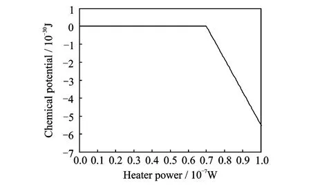
Fig.8 Difference of chemical potential in thermal drive

Fig.9 Josephson frequency in thermal drive
From Figs.8-9,the system maintainsΔ_=0 under the condition of Q<Q c,so there is no Josephson oscillation.Under the condition of Q>Qc,and fJincrease linearly with the increase of Q.Therefore,if keeping Q constant,f J can maintain constant,then the system can work for a long time.
From the above analysis,the total current I of thermal drive can be expressed as I=Is(net)(t)+ Is(dc)(t)+ In(t)+ Iac(t),from Eqs.(7,12),we have

where I s(net)(t)only exits ininitial time,and if the initial timeis t0,thedisplacement of diaphragm is
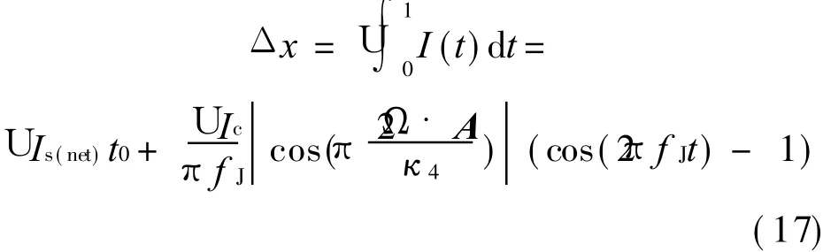
Eqs.(15- 17)are driven,current and position equations of thermal drive.
Simulation parameters are selected as:U I s(net)t0=2× 10⁻¹⁰m,U I c=1.2× 10⁻¹³m/s,fJ=700 Hz.When rotation flux is zero,displacement of diaphragm is shown in Fig.10.When the rotation flux is 0.4,it decelerates from 0.4 to 0.2 within 5.01—5.03 s,and then it keeps 0.2.Displacement of diaphragm is shown in Fig.11.
From Fig.10,the displacement amplitude of diaphragm shows rotation flux is zero.In Fig.11,when rotation flux is 0.4,its amplitude is constant;in the decelerated process of rotation flux,its amplitudeis changed;when rotation flux is 0.2,its amplitude is constant and is bigger than that when rotation flux is 0.4.

Fig.10 Displacement of diaphragm caused by total current in thermal drive(rotation flux is zero)

Fig.11 Displacement of diaphragm caused by total current in thermal drive(rotation flux is varied)
Obviously,in Fig.5(c)and Fig.6(b)the displacement of diaphragm which is caused by total current increases gradually,but in Figs.10-11,the displacement oscillates near its position caused by net current.Therefore,using the way of thermal drive,the4He quantum interferometer gyroscope is not limited by the maximum displacement of diaphragm and can work for a long time.
5 CONCLUSION
In this paper,a mathematical model of4He quantum interferometer gyroscope is presented.The simulations based on this model and the experimental parameters are also proposed.The model which includes driven equation,current equation and position equation can describe this gyroscope system sufficiently.
From the driven equation,it is distinct that the pressure driven system is limited by the maximum displacement of diaphragm and can only work for a short time.While thermally driven system can work for a long time.
From current and position equations,it is clear that the displacement of diaphragm that is detected by SQUID is the total current.The AC current,which is caused by Josephson effect,is needed to reflect the rotation.This current must be selected from the total current.
A lot of work should bedone before applying4He quantum interferometer gyroscope to inertial navigation systems.Based on the model in this paper,the gyroscope performance and error can be further studied.
[1] Anderson P W. Considerations on the flow of superfluid helium[J].Rev Mod Phys,1966,38:298.
[2] Hakonen A P,Varoquaux E.Detection of the rotation of the earth with a superfluid gyrometer[J].Physical Review Letters,1997,78(19):3602-3605.
[3] Mukharsky Y,Avenel O,Varoquaux E.Simulation of a4He superfluid gyrometer with large sensing area[J].Journal of Low Temperature Physics,1998,113(5):915-920.
[4] Schwab K,Brukner N,Packard R.Detection of absolute rotation using superfluid4He[J]. Low Temp Phys,1998,24(2):102-104.
[5] Brucknera N,Packard R. Large area multiturn superfluid phase slip gyroscope[J]. Journal of Applied Physics,2003,93(3):1798-1805.
[6] Packard R,Vitale S.Principles of superfluid-helium gyroscops[J].Physical Review B,1992,46(6):3540-3549.
[7] Chui T, Penanen K. Frequency-dependent hydrodynamic inductance and the determination of thermal and quantum noise of a superfluid gyroscope[J].Ph usical Review B,2005,71(13):132509-1-132509-4.
[8] Simmonds R W,Marchenkov A,Hoskinson E,et al. Quantum interference of superfluid3He[J].Nature,2001,412(6842):55-58.
[9] Hoskinson E,Sato Y,Packard R.Superfluid4He interferometer operating near 2K [J]. Physical Review B,2006,74(10):100509-1-100509-8.
[10]Sato Y. Fiske-amplified superfluid interferometry[J].Physical Review B,2010,81(17):172502-1-172502-4.
[11]Golovashkin I,Zherikhina L N,Tskhovrebov A M,et al. Ordinary SQUID interferometers and superfluid helium matter wave interferometers:The role of quantum fluctuations[J]. Journal of Experimental and Theoretical Physic,2010,111(2):332-339.
[12]Golovashkin A I,Izmai¨lov G N,Ozolin V V,et al.Scheme of laboratory measurements of gravimagnetic effects with SHeQUID equipped with a rotation f lux transformer[J].Gravitation and Comology,2010,16(1):78-84.
[13]Xie Zheng,Liu Jianye,Zhao Wei,et al. The exploratory research of a novel gyroscope based on superfluid Josephson effect[C]//PLANS 2010 Conference.Indian Wells,USA:IEEE,2010:14-19.
[14]Hoskinson E, Packard R. Thermally driven Josephson oscillations in superfluid4He[J].Physical Review Letters,2005,94(15):155303-1-155303-4.
[15]Annett J F. Superconductivity, superfluids,and condensates[M].Beijing:Science Press,2009.
[16]Hoskinson E,Sato Y,Penanen K,et al.A chemical potential"battery"for superfluid4He weak links[C]//AIP Conf Proc.Orlando,USA: American Institute of Physics,2006:117-118.
 Transactions of Nanjing University of Aeronautics and Astronautics2012年4期
- Transactions of Nanjing University of Aeronautics and Astronautics的其它文章
- RELIABILITY EVALUATION MODEL BASED ON DATA FUSION FOR AIRCRAFT ENGINES
- EFFICIENT NUMERICAL METHOD FOR DYNAMIC ANALYSIS OF FLEXIBLE ROD HIT BY RIGID BALL
- TASK ALLOCATION BASED ON PHEROMONE
- DEVELOPMENT AND PRELIMINARY APPLICATION OF OBJECTIFYING SYSTEM FOR TCM COLOR INSPECTION
- FLIGHT CONFLICT FORECASTING BASED ON CHAOTIC TIME SERIES
- FPGA BASED REAL-TIME VIDEO IMAGE ACQUISITION AND STORAGE SYSTEM