
Simulation studies on two-frequency RF gun
2014-03-07 12:24LIDa李达FANGWenCheng方文程GUQiang顾强WANGZhen王震ZHANGMeng张猛TANJianHao谭建豪WANGChaoPeng王超鹏andZHAOZhenTang赵振堂
Nuclear Science and Techniques 2014年4期
LI Da(李达),FANG Wen-Cheng(方文程),GU Qiang(顾强),WANG Zhen(王震),ZHANG Meng(张猛), TAN Jian-Hao(谭建豪),WANG Chao-Peng(王超鹏),and ZHAO Zhen-Tang(赵振堂),
1Shanghai Institute of Applied Physics,Chinese Academy of Sciences,Shanghai 201800,China
2University of Chinese Academy of Sciences,Beijing 100039,China
Simulation studies on two-frequency RF gun
LI Da(李达),1,2FANG Wen-Cheng(方文程),1GU Qiang(顾强),1WANG Zhen(王震),1,2ZHANG Meng(张猛),1TAN Jian-Hao(谭建豪),1,2WANG Chao-Peng(王超鹏),1,2and ZHAO Zhen-Tang(赵振堂)1,∗
1Shanghai Institute of Applied Physics,Chinese Academy of Sciences,Shanghai 201800,China
2University of Chinese Academy of Sciences,Beijing 100039,China
Photocathode RF gun is widely used for particle accelerators as an electron source.When driving an RF electron gun at the fundamental frequency and a higher harmonic frequency simultaneously with proper field ratio and relative phase,it generates electron beams of ultralow emittance and a linear longitudinal phase space distribution.Such a gun provides high quality electron beam with low energy spread,small traverse emittance and high brightness.In this paper,the RF design of a 1.5 cell cavity is presented.Simulation results of beam dynamics for the two-frequency gun and a standard single-frequency RF gun are also shown in this paper.In addition,bunch compression with a two-frequency gun is explored.
RF gun,Two-frequency,Traverse emittance,Emittance compensation,Energy spread,Bunch compression
I.INTRODUCTION
Generating high quality electron beams is a critical issue for free-electron laser(FEL)facilities.The characteristics of electron beams and reliability of an FEL facility strongly depend on properties of the electron source.To get electron beams of sufficient brightness,photocathode RF guns are widely adopted in most FEL facilities nowadays.
Transverse emittance of an RF gun is predominated by space charge forces,RF effects and thermal emittance.As both linear space charge and RF effects can be compensated by solenoid technique[1],the final projected emittance is dominatedbyspacechargeoscillationandemittancecompensation[2,3].Serafini et al.[4]proposed that when an RF gun cavity was operated with an extra harmonic TM012-πmode, the field could neutralize the emittance blowup induced by RF-time-dependent forces.An RF cavity operated at 1.5 and 4.5GHz was designed for PSI-XFEL[5].
For future FEL facilities,the final compression is so extreme that non-linear effects such as sinusoidal RF timecurvature may occur easily.A higher harmonic was proposed to compensate the compression transformation,while maintaining the initial temporal bunch profile.X-band RF harmonic compensation for linear bunch compression has been used in the LCLS[6].Similar schemes have been proposed at DESY[7]and Boeing[8].With harmonic section,a twofrequencyRF guncan provide partialharmoniccompensation for bunch compression.
In this paper,a two-frequency 1.5 cell gun with optimized RF parameters is designed.The scheme adopted is of easier fabrication than the PSI type.Intensive simulations have been carried out.The emittance compensation process of a twofrequency gun is discussed in detail.The process of bunch compression with a two-frequency gun is performed by the lattice of the Shanghai deep ultraviolet FEL facility(SDUVFEL)[9]at SINAP.
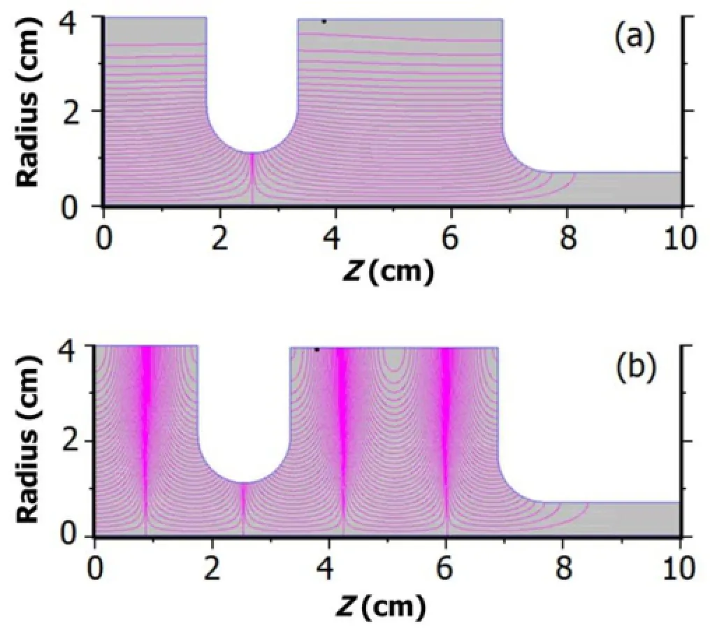
Fig.1.(Color online)Electric field contour lines at the fundamental frequency of 2.998GHz(a)and the 3rdharmonic frequency of 8.994GHz(b).
II.RF CAVITY DESIGN
SUPERFISH[10],which is an excellent code to simulate electromagnetic field,was used to design the cavity. A convergence optimization was performed to ensure that the meshes are small enough for calculating the field accurately.The 1.5 cells RF cavity is supposed to be operated at 2.998GHz and 8.994GHz in TM010-πand TM012-πmodes, respectively.To make the gun operate at the desired frequencies and expected modes,at least two geometric parameters of the cavity are needed to adjust the frequency.According to simulation results,fundamental frequency is sensitive to the radius of cells,while the third harmonic is sensitive to the length of cells.The working modes are shown in Fig.1.Themicrowave parameters computed by SUPERFISH are given in Table 1.

TABLE 1.Microwave parameters of the RF gun from SUPERFISH
The field balance[11]of both modes are almost equal to 1,as shown in Fig.2.A total peak fl at-top on-axial field is obtained when the two modes are in phase opposition, with the fundamental and the 3rdharmonic amplitudes being 100MV/m and 11MV/m,respectively.

Fig.2.(Color online)On-axial electric field.
III.BEAM DYNAMICS SIMULATIONS
Properties of the electron beams generated by the twofrequency RF gun,i.e.beam energy,transverse emittance, the 2ndorder energy chirp and energy spread,were simulated using the codes of ASTRA[12]and ELEGANT[13]. In this paper,the emittance compensation process of a twofrequency RF gun,and all results without the 3rdharmonic, are presented.
To discuss the beam dynamics of an RF gun with a halfcell as the first cell[14],Kim proposed a simple analysis method[15],where the electric field along the axial is assumed as

where E1is the peak accelerating field,ω is the angular frequency,k= ω/c,and ϕ0is the initial injection phase.The exit normalize energy gain for a 1.5 cell gun is given by

where α=eE1/(2m0c2k).So,an extra mode with frequency tripled to the fundamental mode is imported on the fundamental one,the axial electric field can be written as:
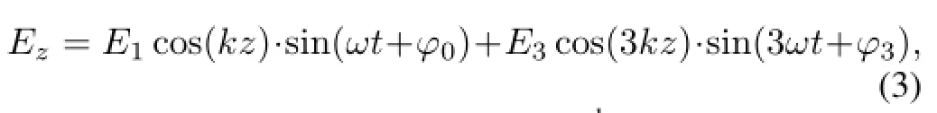
where ϕ3is the initial phase of the 3rdharmonic,E3is the peak accelerating field of the 3rdharmonic.The normalized energy gain from the 3rdharmonic is

From Eqs.(2)and(4),the total energy gain is

For all simulations in this paper,ϕ0and ϕ3stemmed from ASTRA representing the initial phases of fundamental mode and the 3rdharmonic,corresponding to ϕ0and ϕ3in Eq.(3). All simulations in this section were performed with electron beams of Gaussian profiles and in bunch charges of 1nC. To demonstrate the two-frequency RF gun for accelerating long bunches,the pre-accelerated beam length was 20ps,and E3=100MV/m for all cases.
According to Serafini et al.[4],an additional harmonic to the RF fundamental field would greatly reduce the RF emittance.A harmonic RF field shall linearize the RF force to the 4thorder,both longitudinally and transversely[16].The condition can be achieved when the bunch exit phase is 90◦and the n-th harmonic field(En)over the fundamental field(E1) is En/E1=1/n2.In this case,ϕ0=52.5◦is the exit phase for bunch exit phase of 90◦.However,this set of RF parameters are not applicable for emittance compensation,though the RF emittance is minimized.
In an operating BNL type photoinjector,the final projected emittance is dominated by space charge osillation and emittance compensation[2].In order to minimize chromatic aberration effect,ϕ0is always chosen to minimize energy spread at the gun exit.In an optimal case,ϕ0=47◦,ϕ3=4◦and E3=14MV/m,by optimizing the rms energy spread at the gun exit.With this set of RF parameters,the 2ndorder energy chirp and the emittance compensation can be optimized.
A.Beam energy
At ϕ0=47◦,the effect of the 3rdharmonic on beam energy is simulated.According to Eq.(5),the beam energy at the gun exit is decided by the fundamental mode and the 3rdharmonic.As shown in Fig.3(a),with harmonic field amplitude fixed,Δγ is a sinusoidal function of ϕ3,agreeing with Eq.(5);while with ϕ3fixed(Fig.3(b)),Δγ3varies linearly with E3,agreeing with Eq.(4).

Fig.3.(Color online)Beam energy at the gun exit(a)vs.initial phase of the 3rdharmonic,at E1=100MV/m and ϕ0=47◦(each line corresponds with a certain value of E3),and energy gain from the harmonic at ϕ3=190◦(b).
B.RF emittance,energy spread and the longitudinal phase space
To illustrate the RF emittance reduction by harmonic field, thespacechargeeffectisswitchedoff,andϕ0=52.5◦issuggested by the theory[16].In presence of the 3rdharmonic, the RF emittance is reduced,compared with the case without the 3rdharmonic(Fig.4(a)).By optimizing the energy spread at the gun exit at ϕ0=47◦under space charge,we found optimal harmonic settings for the two-frequency RF gun:ϕ3=4◦and E3=14MV/m(Fig.4(b)).
To discuss the longitudinal phase space distribution,we performed a linear fitting of the relative energy deviation, which is a function of the relative position to a reference particle,it is given by

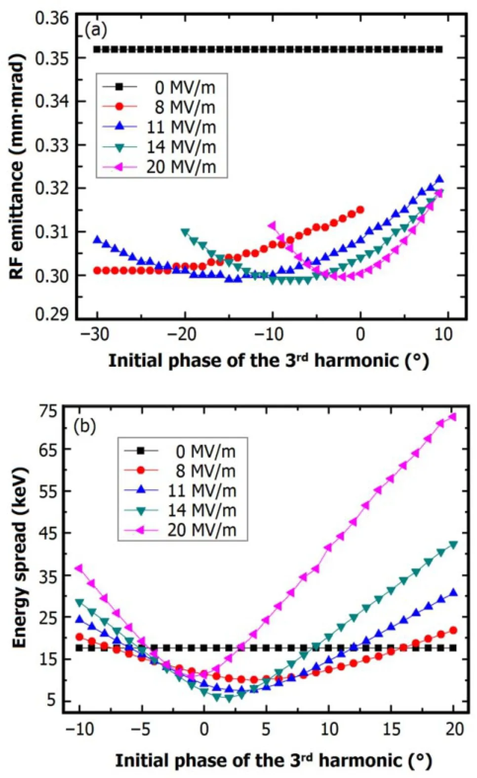
Fig.4.(Color online)RF emittance(a)and energy spread(b)at the gun exit in absence of space charge,as function of initial phase of the 3rdharmonic in different amplitudes at E1=100MV/m and ϕ0=52.5◦.Each line corresponds with certain value of E3.
whereaandbarethecoefficientsrelatedtolongitudinalphase space,E0is energy of the reference particle,ΔE is the relative energy of the electron to the reference particle,and Z is the longitudinal position of the electron with respect to the reference particle.
The second derivative of ΔE/E0(Z)represents the 2ndorder energy chirp,which can be removed at b=0.At ϕ0= 47◦,simulations of the 2ndorder energy chirp as function of the amplitude of harmonic field was performed in presence of the space charge.In addition,at ϕ3=4◦, so that the maximum efficiency for linearizing longitudinal phase space is achieved according to Fig.4(b).At ϕ0=47◦, E1=100MV/m and ϕ3=4◦,coefficient b was-16.78/m2, -5.57/m2,-0.13/m2and 4.34/m2at E3=0,10,14 and 20MV/m,respectively.The 2ndorder energy chirp could be almost compensated by the 3rdharmonic at E3=14MV/m, compared with the case of no 3rdharmonic.However,if the harmonic field amplitude exceeds certain threshold,the 2ndorder energy chirp would be over compensated.
Figure 5(a)shows that for 20-ps bunches,the 3rdharmonichas linearized the longitudinal phase space in absence of the space charge.The 2ndorder energy chirp is removed by 3rdharmonic at E3=14MV/m and ϕ3=4◦.The 3rdharmonic has improved the longitudinal phase space in presence of the space charge(Fig.5(b)).The full width,correlated energy spread is reduced from 90keV to 50keV.
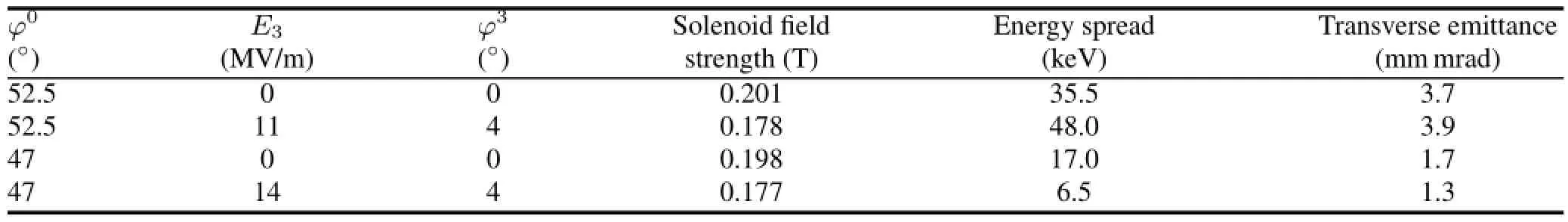
TABLE 2.Transverse emittance at the drift exit at different initial fundamental mode phase with or without the 3rdharmonic in presence of the space charge.For each case the solenoid field is optimized,at E1=100MV/m and bunch charge=1nC

Fig.5.(Color online)Longitudinal phase space at 1nC with and without harmonics,in absence(a)and presence(b)of the space charge,at ϕ0=47◦,E1=100MV/m and ϕ3=4◦.
C.Emittance compensation of a two-frequency RF gun
To illustrate the right set of RF parameters for emittance compensation,a transverse emittance monitoring point is set at the exit of a 1.5m drift downstream the gun.As shown in Table 2,at ϕ0=52.5◦the energy spread at gun exit and the transverse emittance are bigger than at ϕ0=47◦.The energy spread at the gun exit is not minimized at ϕ0=52.5◦, which indicates that the chromatic aberration effect is not minimized,so that the emittance compensation proceeds incorrectly.At ϕ0=47◦,E3=14MV/m and ϕ3=4◦,the energy spread is minimized,so that the transverse emittance at the drift exit is optimized.
IV.BUNCH COMPRESSION WITH A TWO-FREQUENCY GUN
As mentioned above,the 3rdharmonic helps linearize the energy chirp for the process of bunch compression.What is more,by over compensating the 2ndorder energy chirp which imports an extra 2ndorder energy chirp,the two-frequency gun can provide harmonic compensation for bunch compression[6].As mentioned in Sec.III B,such an extra 2ndorder energy chirp can be produced at E3=20MV/m.The lattice of SDUV-FEL at SINAP,as shown in Fig.6,was used to simulate the process of bunch compression,performed with a 800-pC 20-ps long bunch in presence of the space charge.All settings of the S-band and chicane are the same for the cases with and without the 3rdharmonic.
As shown in Fig.7(a),the 3rdharmonic could improve the beam current distribution at the exit of the bunch compressor.The symmetry bunch distribution of the case with the 3rdharmonic is better than the case without the 3rdharmonic. As mentioned in Sec.III B,the bunch shall be over compensated at the gun exit by the 3rdharmonic at E3=20MV/m. To evaluate its effect on emittance compensation,the transverse emittance is studied in presence of the space charge. As shown in Fig.7(b),the transverse emittance evolution is not deteriorated obviously,compared with the optimal case in Table 2.
V.CONCLUSION

Fig.6.(Color online)The lattice of SDUV.

Fig.7.(Color online)Beam current(a)and transverse emittance(b)as function of relative distance at the exit of chicane at 800pC of charge, at E1=100MV/m,E3=20MV/m,ϕ0=47◦and ϕ3=4◦.
A 1.5 cell two-frequency RF gun,working at 2998MHz and 8994MHz,is designed by SUPERFISH.Beam dynamics simulations demonstrate the advantages of a two-frequency RF gun over a single-frequency gun when generating high charge(nC)and high brightness electron beams.Besides, harmonic compensation for bunch compression by manipulating the harmonic component in the two-frequency RF gun is explored.Compared with a single-frequency RF gun without a harmonic linac,simulations show a symmetric bunch compression with comparable transverse emittance.Compared with the case of two-frequency gun without harmonic compensation,the transverse emittance is a bit larger,which indicates the extra 2ndorder energy chirp in the gun for downstream beam energy chirp linearization deteriorates the emittance compensation.
[1]Kim K J.Nucl Instrum Meth A,1989,275:201–218.
[2]Serafini L and Rosenzweig J B.Phys Rev E,1997,55:7565–7590.
[3]Dowell D H,Ferrario M,Kimura T,et al.Nucl Instrum Meth A,2004,528:316–320.
[4]Serafini L,Rivolta R,Pagani C,et al.Nucl Instrum Meth A, 1992,318:301–307.
[5]Raguin J Y,Li K,Bakker R,et al.Nucl Instrum Meth A,2008, 593:125–128.
[6]The LCLS Design Study Group.Linac Coherent Light Source Design Study Report.Stanford,California,SLAC-R-521, 1998.
[7]Floettmann K,Ferrario M,Grigoryan B,et al.The TESLA XFEL Injector,Proceedings of Particle Accelerator Conference 2001,Chicago,June 18–22,2001.
[8]Dowell D H,Hayward T D,Vetter A M,et al.Magnetic Pulse Compression Using a Third Harmonic Linearizer,Proceedings of Particle Accelerator Conference 1995,Dallas,May 1–5, 1995.
[9]Zhao Z T,Lin Y Z,Wang H Y,et al.Nucl Instrum Meth A, 2004,528:591–594.
[10]Billen J H and Young L M.Poisson/Superfish,Los Alamos National Laboratory,LA-UR-96-1834,1996.
[11]Kashiwagi S,Kato R,Morio Y,et al.Proceedings of FEL 2009, Liverpool,UK,August 18–23,2009.
[12]Fl¨ottman K.ASTRA,DESY,Hamburg,www.desy.de/ ˜mpyflo,2000.
[13]Elegant B M.A Flexible SDDS-Compliant Code for Accelerator Simulation.Advanced Photon Source LS-287,2000.
[14]Newnam B E,Warren R W,Goldstein J C,et al.Nucl Instrum Meth A,1992,318:197–200.
[15]Kim K J.Nucl Instrum Meth A,1988,275:201–218.
[16]Zhao Z T,Lin Y Z,Wang H Y.Chinese Phys C,1994,18:664–672.
(Received February 20,2014;accepted in revised form April 16,2014;published online August 10,2014)
10.13538/j.1001-8042/nst.25.040101
∗Corresponding author,zhaozhentang@sinap.ac.cn
猜你喜欢
湘潮(上半月)(2021年10期)2021-12-02
湘潮(上半月)(2021年4期)2021-07-20
Plasma Science and Technology(2021年5期)2021-05-22
作文周刊·小学二年级版(2020年20期)2020-09-02
作文周刊·小学一年级版(2018年21期)2018-09-10
故事会(2018年1期)2018-01-10
蓝盾(2017年7期)2017-09-06
作文评点报·作文素材初中版(2017年21期)2017-06-23
作文周刊·小学一年级版(2016年6期)2016-08-12
Nuclear Science and Techniques(2014年1期)2014-04-24
 Nuclear Science and Techniques2014年4期
- Nuclear Science and Techniques的其它文章
- Tidal effects on hydrostatic leveling system used in high precision alignment of particle accelerator∗
- External micro-PIXE analysis of Nd3+accumulation in Euglena gracilis∗
- Mass thickness measurements for dual-component samples utilizing equivalent energy of X-rays∗
- Synthesis of N,N′-dimethyl-N,N′-didecyl-3-oxa-diglycolamide for extraction of lanthanides∗
- A K-CELL injection system for SH-PermEBIT∗
- Improved preparation and chemical kinetics on fully automated synthesis of[18F]-THK523,a PET imaging probe for Tau pathologies∗