
Convective Heat Transfer Enhancement of a Rectangular Flat Plate by an Impinging Jet in Cross Flow*
2014-07-18 12:09LIGuoneng李国能ZHENGYouqu郑友取HUGuilin胡桂林andZHANGZhiguo张治国DepartmentofEnergyandEnvironmentSystemEngineeringZhejiangUniversityofScienceandTechnologyHangzhou310023China
关键词:桂林
LI Guoneng (李国能)**, ZHENG Youqu (郑友取), HU Guilin (胡桂林) and ZHANG Zhiguo (张治国)Department of Energy and Environment System Engineering, Zhejiang University of Science and Technology, Hangzhou 310023, China
Convective Heat Transfer Enhancement of a Rectangular Flat Plate by an Impinging Jet in Cross Flow*
LI Guoneng (李国能)**, ZHENG Youqu (郑友取), HU Guilin (胡桂林) and ZHANG Zhiguo (张治国)
Department of Energy and Environment System Engineering, Zhejiang University of Science and Technology, Hangzhou 310023, China
Experiments were carried out to study the heat transfer performance of an impinging jet in a cross flow. Several parameters including the jet-to-cross-flow mass ratio (X=2%-8%), the Reynolds number (Red=1434-5735) and the jet diameter (d=2-4 mm) were explored. The heat transfer enhancement factor was found to increase with the jet-to-cross-flow mass ratio and the Reynolds number, but decrease with the jet diameter when other parameters maintain fixed. The presence of a cross flow was observed to degrade the heat transfer performance in respect to the effect of impinging jet to the target surface only. In addition, an impinging jet was confirmed to be capable of enhancing the heat transfer process in considerable amplitude even though the jet was not designed to impinge on the target surface.
impinging jet, cross flow, convection heat transfer, heat transfer enhancement
1 INTRODUCTION
Impinging jets are encountered in many industrial applications, e.g. internal vane cooling in high performance gas turbines, flow beneath of a short/vertical take-off aircraft when lifting off or landing, the antisediment jets in thermal or nuclear power plants, and control of thermoacoustic instability in gas turbine combustors. Therefore, great interest has been attracted to study of the physics of flow and heat transfer phenomena. Many empirical correlations of convective heat transfer coefficient of impinging jets are available at present. Comprehensive literature reviews of most impinging jet studies before 2006 were reported [1-2], offering valuable comparisons and discussions among the available experimental data, numerical results and correlations.
Recent studies continue to explore the influences of jet inclination [3, 4], nozzle shape [5-8], jet pulsation [9-12], jet swirling intensity [13-15], jet fluid [16, 17] and jet confinement [18, 19] on the characteristics of flow field and heat transfer of an impinging jet system. The convection heat transfer coefficient was found to increase with jet inclination angle [3, 4] and jet pulsation amplitude [11, 12]. Cross-shaped nozzle was found to improve the heat transfer process by 40%-175% [7] compared to that of a circular pipe nozzle. The swirling impinging jet was observed to enhance the heat transfer performance when the swirl number equals to 0.4 compared to that of a non-swirling impinging jet [13]. The impinging jet of air mixed with water droplets was found to produce larger convective heat transfer coefficient compared to that of an air impinging jet [16, 17]. The confinement of the impinging jet was confirmed to degrade the heat transfer performance [18, 19]. A detailed flow visualization of an impinging jet was obtained [20], and various vortex structures were found. New experimental data on the micro-scale and millimeter-scale impinging jets were reported [21, 22], and differences of heat transfer characteristics were observed between the micro-scale impinging jets and macro-scale impinging when the Reynolds number is larger than 2500 [21]. Detailed hydrodynamic physics of the impinging jet was studied [23-25]. It is found that there is a linkage between the local heat transfer rate and the turbulence intensity of the impinging jet [23]. The main re-circulating flow cannot be captured well unless the outflow is placed at least at 40 times of the jet diameter from the jet centerline [25]. A new technique, i.e. micro-pin fins, was employed to enhance the heat transfer performance [26], and over 200% increase was found compared to that using a flat target surface. Little information about the effect of a cross flow on the flow field and the heat transfer performance of an impinging jet was provided in the above studies. However, impinging jets in a cross flow are encountered in many industrial processes, such as the separated over-fire air (SOFA) jets in the furnace of a large capacity utility boiler, and the air-liquid two-phase jets in the selective non-catalytic reduction (SNCR) technology in reducing NOxemissions. It is worthy to study the heat transfer characteristics of an impinging jet with a cross flow.
The influences of a cross flow on the flow field characteristics and the heat transfer performance of an impinging jet have been studied by several researchers [27-36], and the cross flow in these studies can be categorized into two series, i.e. the cross flow due to spent flow passing through a confined channel [27-29] and the initial cross flow introduced by design [30-36]. The effects of a cross flow due to spent flows were summarized based on several works conducted in1980s [2], i.e. the cross flow tends to disturb the impinging jet pattern, thicken wall boundary layers, and degrade the heat transfer performance. Recently, a solution was found to partly solve this problem [28]. The flow field of an impinging jet in a cross flow introduced by design was studied in detail [30-34], indicating that a ground vortex was observed, which is caused by the interaction between the impinging jet and the cross flow. This vertical structure wraps around the impinging jet like a scarf [32]. In order to predict the flow field accurately, the method of large eddy simulation (LES) should be adopted [33]. Only a few works were carried out to investigate the heat transfer performance when a cross flow was introduced by design [35, 36]. It is found that the size of the re-circulation region just upstream of the jet and the length of the potential core of the jet are the important flow characteristics that affect the heat transfer performance [36]. New experimental data are obviously needed. Our previous work found that a high momentum jet issuing into the cross flow (up-flowing fluids in a combustion chamber) improved the combustion efficiency (heat transfer rate) and suppressed the thermoacoustic instability by over 90% [37]. In this work, the heat transfer performance of a heated rectangular flat plate subjected to an impinging jet with a cross flow was studied under different jet-to-cross-flow mass ratios, Reynolds numbers and jet diameters. The results will help to find out the exact influence of a cross flow on the heat transfer performance of an impinging jet system. In addition, a specific application of the present results is presented toward increasing the convection heat transfer coefficient of the tube-type heat exchanger by introducing an impinging jet ahead of the heat exchanger.
2 EXPERIMENTAL APPARATUS AND PROCEDURE
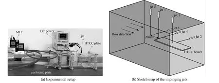
Figure 1 Experimental setup and the sketch map of the impinging jets
The experimental system is shown in Fig. 1. The experiments were conducted in a Plexiglas square channel with crossing-section of 80 mm×80 mm and a length of 500 mm. A transition zone and two staged, 20 mm thick perforated plates with opening fraction of 0.75 were installed to ensure the uniformity of the inlet cross flow. A high temperature co-fired ceramic (HTCC) rectangular flat plate heater with dimensions of 70 mm×20 mm×1.5 mm was fixed 60 mm downstream the second perforated plate, and in the center of the cross-section. The 70 mm side of the HTCC heater was aligned with the channel axis. The fabrication of the HTCC heater was notably complex. In brief, the slurry composed of wolframium, molybdenum and manganese was printed on an Al2O3embryonic flat plate according to the exothermic electric circuit and subsequently co-fired in a sintering circuit at 1700-2000 K to obtain the final HTCC heater. The preeminent feature of the HTCC heater lies in its uniform heat flux on the outside surface since the Bi number is very small, and it will be discussed in Section 3. The electric resistance of the HTCC heater changes linearly with temperature. The connecting wires are connected to the HTCC heater with two contact strips which were buried inside the HTCC plate in order to obtain a uniform heat flux. The voltage drop in the connecting wires was not taken into consideration in this work and measurements indicated that the voltage loss can be neglected.
Different holes were drilled to install the impinging jets shown in Fig. 1 (b). The jet diameter (d) varied in the range of 2-4 mm and the jet length (L) was 30 mm. During experiments, only one impinging jet was operated while other holes were sealed hermetically. Jet 1 (d=2-4 mm) is located on the top surface of the square channel with its central axis crossing through the central axis of the square channel. The jet-to-surface spacing (H/d) is 9.813-19.625, where H=39.25 mm denotes the distance between the jet nozzle and the surface of the HTCC heater. The installation of jets 3 and 5 is shown in Fig. 2. Jets 2, 4and 6 were flush mounted in the sidewall of the square channel with their axis in the HTCC heater plane. The cross flow and the impinging jet were supplied from a 1 m3air tank with the air flow rates set by two Alicat®mass flow controllers. The accuracy of the mass flow controller was ±0.8% of reading plus 0.1% of the full scale (the cross flow mass flow controller: 3333.3 ml·s−1, the jet flow mass flow controller: 333.3 ml·s−1), while the stocking pressure of the air tank was maintained by an automatic air compressor. The HTCC heater was powered by a direct current (DC) power supply QJ®-3003XE with an accuracy of 0.01 W.
The experiment was initiated by installing one impinging jet (d=2 mm) only. The air was supplied into the channel at a fix rate to from a steady cross flow, and no air supplied to the jet. The HTCC heater was heated to a thermally steady state, which was defined as when the variation of the total heat flux (E= 3.00 W) of HTCC heater was within 0.05 W for 5 min. In other words, the variation of the averaged surface temperature of HTCC heater was less than 0.5 K for 5 min. Then, air was supplied into the impinging jet with different jet-to-cross-flow mass ratios (X=QJ/Qtot) to investigate the influence of the impinging jet on the heat transfer performance. At last, the cross flow was stopped, and the heat transfer performance was examined with the impinging jet in operation. The above experiment was repeated similarly for other jets.
For Jet 1 with d=2 mm and X=4%, the air flow rate of the cross flow varied in the range of 833.3-3333.3 ml·s−1to investigate the influence of Reynolds number (Red) on the impinging jet performance. Finally, for jet 1 with Red=2868 and X=4%, the jet diameter varied in the range of 2-4 mm to study the influence of the jet diameter on the impinging jet performance. The experimental cases were shown in Table 1.

Table 1 Experimental cases and the inlet air temperature
3 DATA REDUCTION
The Reynolds number (Red), the convection heat transfer coefficient (h) and the heat transfer enhancement factor (Nur) were defined as
whereJu and v are the time-averaged velocity of the impinging jet and the kinematic viscosity of air, respectively. E and T are the total heat flux and the averaged surface temperature of the HTCC heater, respectively. λ is the thermal conductivity of the air, which was assumed to be constant in this work since the variation of λ is less than 3.2% in the present experiments. h is the convection heat transfer coefficient. S=15.671 mm2is the area of the outside surface of the HTCC heater, Lc=70 mm is the characteristic length of the HTCC heater, and T0is the inlet air temperature. The σ is the Stefam Boltzmann constant, which equals to 5.67×10⁻⁸W·m−2·K−4. The subscripts JICF and non-JICF denote the flow condition with an impinging jet and that without an impinging jet, respectively. In this study, the HTCC heater was assumed to adopt the gray body model, and the radiation emissivity ε=0.68 [38] was assumed to equal the absorptivity. The error of Nurwas estimated to be less than 6.7% when ε varies in the range of 0.5 to 0.9 in the present experiments. Under the assumption of constant thermal conductivity of air and a radiation emissivity (ε) of 0.68 equal to the absorbtivity, total differential method was applied to estimate the uncertainty for the Nusselt number with Eq. (5):
The uncertainty for the Nusselt number was estimated to be 4.1% at the 95% confidence level.
It proved difficult to obtain an accurate measurement of the averaged surface temperature for a heated surface in air flow. The use of thermocouples would disrupt the flow which could seriously affect the heat transfer process. In addition, an infrared thermal imager is designed to be used under steady conditions. The fluctuation of the temperature field due to the vortex movement around the HTCC heater could lead to incorrect results. In this study, the averaged temperature of the HTCC heater was taken as the averaged surface temperature. The maximum Bi number was calculated to be less than 0.0016 with Eq. (6) based on the obtained experimental results:
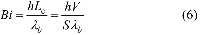
This indicates that the temperature fields inside the HTCC body are thermally simple and can be assumed to be uniform.
This assumption was also confirmed through both experimental data and computational fluid dynamics(CFD) results (not showed in this paper). An advantage of using an HTCC heater is that the electric resistance changes linearly with temperature. The correlation between the electric resistance of the HTCC heater and the averaged surface temperature is shown in Fig. 2, which was obtained from the results of a separate calibration experiment. The experiments were carried out using a constant-temperature-humidity machine ACS®H250 and an Agilent®34970A resistance meter. The calibration procedure is as follows: (1) the temperature and the humidity of the ACS®H250 were set to be the desired values, (2) the HTCC heater was placed into the ACS®H250, where it remained until reaching thermal steady state, and (3) the Agilent®34970A was used to measure the electric resistance of the HTCC heater. The procedure was repeated to obtain Fig. 2.

Figure 2 Correlation between the electric resistance of the HTCC plate and the temperature
4 RESULTS AND DISCUSSION
4.1 Influences of the jet position and X on Nur
The averaged surface temperatures of the HTCC plate heater under different impinging jets (jet 1 to jet 6) and jet-to-cross-flow mass ratios (X) when Red= 2868 and d=2 mm are shown in Fig. 3. The averaged surface temperature was found to decrease with X for all impinging jets in a similar trend, but in different extents. jet 1 was found to be most capable of decreasing the averaged surface temperature, while jets 5 and 6 were the weakest in decreasing the averaged surface temperature. The decreases of the averaged surface temperature were calculated to be 25.75 K and 25.02 K for jet 5 and jet 6 when X=8%, respectively, indicating that large increase in convection heat transfer coefficient can be obtained.
In present experiments, the convective heat flux takes most of the total heat flux, and it is more convenient to study the convection heat transfer enhancement by impinging jets. However, it never means the radiation heat flux can be neglected. Fig. 4 shows the ratio of radiation heat flux to the total heat flux for different impinging jets and X when Red=2868 and d=2 mm. Erad/Etotis larger than 28% for the experimental case without an impinging jet, and it is larger than 5% for all experimental cases. As a result, the radiation heat flux must be taken into consideration in calculating the convection heat transfer coefficient (h) and the Nusselt number (Nu).

Figure 3 The calculated averaged surface temperature of the HTCC plate (Red=2868, d=2 mm)
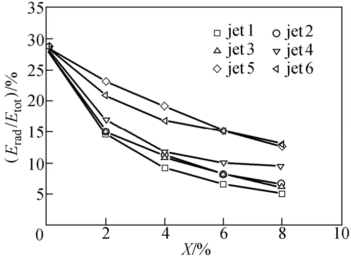
Figure 4 The ratio of calculated radiation heat flux to the total heat flux (Red=2868, d=2 mm)

Figure 5 The calculated heat transfer enhancement factor of the HTCC plate (Red=2868, d=2 mm, h0=13.42 W·m−2·K−1)
The heat transfer enhancement factor of the HTCC plate heater under different impinging jets and X when Red=2868 and d=2 mm are shown in Fig.5. jet 1 was found to increase the convection heat transfer coefficient greatly. Jet 5 and jet 6 were observed to enhance the heat transfer process even though they were not designed to directly impinge on the target surface. This phenomenon may caused by the vortex systems in a jet-in-cross-flow (JICF) system [39, 40], i.e. the horseshoe vortices, the shear layer vortices, thecounter-rotating vortex pair (CVP) and the wake vortices. These vortices were found to interact with each other, and move downstream to affect the boundary layer of the HTCC heater. In addition, the above mechanism can be used to explain the performance of jet 2 and jet 4, which were found to act well to enhance the heat transfer process.
4.2 Influences of the Reynolds number
The convective heat transfer coefficients for the experiments without impinging jets are shown in Fig. 6, indicating that the effect of increasing the convection heat transfer coefficient by increasing the inlet flow velocity is limited. The heat transfer enhancement factor for an impinging jet with/without a cross flow was shown in Fig. 7. The heat transfer enhancement factor was found to increase obviously with the Reynolds number, which is consistent with previous conclusions, i.e. Nuris direct proportional to Red[2, 5]. For situations without a cross flow, many valuable Nusselt number correlations were developed [41-43], and a correlation for a single round pipe nozzle impinging jet without a cross flow covers the present experimental parameters [42] is as follows:
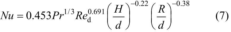
where Pr is the Prandtl number of air, Reddenotes the Reynolds number calculated based on the impinging jet diameter and the jet velocity, R is the measured radius from jet axis. The ranges of validity of Eq. (7) are 2≤R/d≤30, 6≤H/d≤58 and 3400≤ReJ≤41000, respectively. All the parameters in the present experiments fall into the range of Eq. (7) except Redwas varied in the range of 1434-5735. The heat transfer enhancement factors predicted by Eq. (7) are also in Fig. 7. As shown in Fig. 7, the heat transfer enhancement factors in this work were found to agree well with the predicted results. Eq. (7) was found to under predict the heat transfer enhancement factor with a largest difference of 6.8%. This validation provides confidences for the present experimental system.
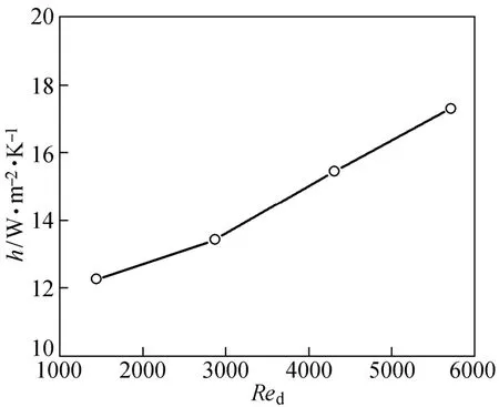
Figure 6 Effect of the Reynolds number on the convection heat transfer coefficient of the HTCC plate (X=0)

Figure 7 Effect of the Reynolds number on the heat transfer enhancement factor and on the radiation heat flux (X=4%, d=2 mm, jet 1)
For situations with a cross flow, the present experimental parameters were found to be outside of the ranges of the previous work [35] on impinging jets with a cross flow. Therefore, no comparison can be made. As shown in Fig. 7, the cross flow was found to downgrade the heat transfer performance by 13.6% in average under the present study parameters. It is consistent with the conclusion obtained in a previous work with shorter jet-to-surface spacing and larger Reynolds number [35]. The underling mechanism controlling this phenomenon is complicated, and needs further investigation. Present experiments were designed to maintain the jet-to-cross-flow mass ratio (X=4%). The trajectory of the impinging jet can be predicted with a regression formula [44] as follows:
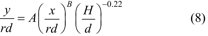
where r (r=uJ/uc) donates jet-to-cross-flow velocity ratio, A and B are constants varied in the ranges of 1.2-2.6 and 0.28-0.34, respectively. The jet-to-crossflow velocity ratio maintains constant (r=84.89) when the jet-to-cross-flow mass ratio is the same (X=4%). As a result, the central trajectories for these experiments should be the same. The impinged point (yavg) should be located about 0.82 mm (yavg=0.5ymax+ 0.5ymin) downstream the impinging jet axis according the above regression formula. This displacement of 0.82 mm is very small, which has minor effects on the downstream impinging heat transfer. However, the interaction between the cross flow and the impinging jet will downgrade the heat transfer upstream of the impinging region [35] since the spread out of the impinging jet flow was suppressed due to the blockage effect [39].
4.3 Influences of the impinging jet diameter
The heat transfer enhancement factor and the ratio of radiation heat flux to total heat flux are shown in Fig. 8. The heat transfer enhancement factor was found to decrease with the jet diameter. An impinging jet with larger jet diameter and with the same air mass flow rate results in lower Reynolds numbers (Red=4QJ/πdv), therefore, the results of Fig. 8 are consistent with results from Fig. 7. Another explanation can be made using Eq. (8). The jet-to-cross-flow velocity ratio (r) was calculated to decrease sharply with jet diameter, resulting in more serious bending of the impinging jet. The impinged point (yavg) should be located about 10.39 mm downstream the impinging jet axis according Eq. (8) when d=4 mm. As a result, the effective zone by the impinging jet should decreased, which resulted in larger averaged surface temperature. No comparison can be made, since no correlation can be found for the present experiments. However, results revealed that the jet diameter should be carefully optimized in order to obtain better heat transfer performance when an impinging jet is adopted. On the other hand, for the situations of increasing the jet diameter while keeping the velocities of the jet and the cross flow unchanged, the heat transfer should be improved since larger impinging areas can be obtained [the impinged point (yavg) maintains unchanged]. However, it is out of range of present study.
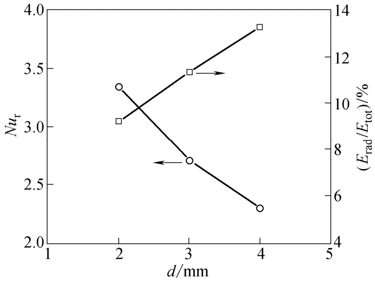
Figure 8 Effect of the jet diameter on the heat transfer enhancement factor and on the radiation heat flux (Qtot= 1666.7 ml·s−1, X=4%, jet 1)
5 CONCLUSIONS
An experimental study was conducted to explore the convection heat transfer enhancement by an impinging jet in a cross flow. Several parameters including the jet-to-cross-flow mass ratio (X=2%-8%), the Reynolds number (Red=1434-5735) and the jet diameter (d=2-4 mm) were explored to find out the influences of the cross flow on the heat transfer performance in a impinging jet system. Several conclusions were drawn after analyzing the obtained results:
(1) The heat transfer enhancement factor is found to increase with the jet-to-cross-flow mass ratio when the Reynolds number and the jet diameter remain constant, and it increases with the Reynolds number when the jet-to-cross-flow mass ratio and the jet diameter remain constant. However, it is observed to decrease with jet diameter when other conditions are maintained constant. The jet diameter should be carefully optimized in order to obtain better heat transfer performance.
(2) The presence of a cross flow degrades the heat transfer performance by 13.6% in average under the present study parameters, which is caused by the blockage effect of the cross flow.
(3) Impinging jets are found to be capable of enhancing the heat transfer process even though the jet was not designed to impinge on the target surface. The vortices created in a JICF system move downstream, and help to improve the heat transfer process. The heat transfer enhancement factor was found to be considerably large (up to 2.3).
NOMENCLATURE

Subscripts

REFERENCES
1 Downs, S.J., James, E.H., “Jet impingement heat transfer: A literature survey”, In: National Heat Transfer Conference, Pennsylvania, Paper 87-HT-35 (1987).
2 Zuckerman, N., Lior, N., “Jet impingement heat transfer: Physics, correlations, and numerical modeling”, Adv. Heat Transfer, 39 (1), 565-631 (2006).
3 Akansu, Y.E., Sarioglu, M., Kuvvet, K., Yavuz, T., “Flow field and heat transfer characteristics in an oblique slot jet impinging on a flat plate”, Int. Comm. Heat Mass Transfer, 35 (7), 873-880 (2008).
4 Choo, K., Kang, T.Y., Kim, S.J., “The effect of inclination on impinging jets at small nozzle-to-plate spacing”, Int. J. Heat Mass Transfer, 55 (13-14), 3327-3334 (2012).
5 Gulati, P., Katti, V., Prabhu, S.V., “Influence of the shape of the nozzle on local heat transfer distribution between smooth flat surface and impinging air jet”, Int. J. Therm. Sci., 48 (3), 602-617 (2009).
6 Koseoglu, M.F., Baskaya, S., “The role of jet inlet geometry in impinging jet heat transfer, modeling and experiments”, Int. J. Therm. Sci., 49 (8), 1417-1426 (2010).
7 Kristiawan, M., Meslem, A., Nastase, I., Sobolik V., “Wall shear rates and mass transfer in impinging jets: Comparison of circular convergent and cross-shaped orifice nozzles”, Int. J. Heat Mass Transfer, 55 (1-3), 282-293 (2012).
8 Buchlin, J.M., “Convective heat transfer in impinging-gas-jet arrangements”, J. Appl. Fluid Mec., 4, 137-149 (2011).
9 Xu, P., Yu, B.M., Qiu, S.X., Poh, H.J., Mujumdar, A.S., “Turbulent impinging jet heat transfer enhancement due to intermittent pulsation”, Int. J. Therm. Sci., 49 (7), 1247-1252 (2010).
10 Qayoum, A., Gupta, V., Panigrahi, P.K., Muralidhar, K., “Perturbation of a laminar boundary by a synthetic jet for heat transfer enhancement”, Int. J. Heat Mass Transfer, 53 (23-24), 5035-5057 (2010).
11 Roux, S., Fénot, M., Lalizel, G., Brizzi, L.E., Dorignac, E., “Experimental investigation of the flow and heat transfer of an impinging jet under acoustic excitation”, Int. J. Heat Mass Transfer, 54 (15-16), 3277-3290 (2011).
12 Klein, D., Hetsroni, G., “Enhancement of heat transfer coefficients by actuation against an impinging jet”, Int. J. Heat Mass Transfer, 55 (15-16), 4183-4194 (2012).
13 Nuntadusit, C., Wae-hayee, M., Bunyajitradulya, A., Eiamsa-ard, S.,“Visualization of flow and heat transfer characteristics for swirling impinging jet”, Int. Comm. Heat Mass Transfer, 39 (5), 640-648 (2012).
14 Nanan, K., Wongcharee, K., Nuntadusit, C., Eiamsa-ard, S., “Forced convective heat transfer by swirling impinging jets issuing from nozzles equipped with twisted tapes”, Int. Comm. Heat Mass Transfer, 39 (6), 844-852 (2012).
15 Nuntadusit, C., Wae-hayee, M., Bunyajitradulya, A., Eiamsa-ard, S.,“Heat transfer enhancement by multiple swirling impinging jets with twisted-tape swirl generators”, Int. Comm. Heat Mass Transfer, 39 (1), 102-107 (2012).
16 Pakhomov, M.A., Terekhov, V.I., “Enhancement of an impingement heat transfer between turbulent mist jet and plat surface”, Int. J. Heat Mass Transfer, 53 (15-16), 3156-3165 (2010).
17 Choo, K.S., Kim, S.J., “Heat transfer and fluid flow characteristics of two-phase impinging jets”, Int. J. Heat Mass Transfer, 53 (25-26), 5692-5699 (2010).
18 Choo, K.S., Kim, S.J., “Comparison of thermal characteristics of confined and unconfined impinging jets”, Int. J. Heat Mass Transfer, 53 (15-16), 3366-3371 (2010).
19 Pakhomov, M.A., Terekhov, V.I., “The effect of confinement on the flow and turbulent heat transfer in a mist impinging jet”, Int. J. Heat Mass Transfer, 54 (19-20), 4266-4274 (2011).
20 Duda, J.C., Lagor, F.D., Fleischer, A.S., “A flow visualization study of the development of vortex structures in a round jet impinging on a flat plate and a cylindrical pedestal”, Exp. Therm. Fluid Sci., 32 (8), 1754-1758 (2008).
21 Choo, K.S., Youn, Y.J., Kim, S.J., Lee, D.H., “Heat transfer characteristics of a micro-scale impinging slot jet”, Int. J. Heat Mass Transfer, 52 (13-14), 3169-3175 (2009).
22 Lee, D.H., Park, H.J., Ligrani, P., “Milliscale confined impinging slot jets: Laminar heat transfer characteristics for an isothermal flat plate”, Int. J. Heat Mass Transfer, 55 (9-10), 2249-2260 (2012).
23 Koseoglu, M.F., Baskaya, S., “The effect of flow field and turbulence on heat transfer characteristics of confined circular and elliptic impinging jets”, Int. J. Therm. Sci., 47 (10), 1332-1346 (2008).
24 Karwa, N., Schmidt, L., Stephan, P., “Hydrodynamics of quenching with impinging free-surface jet”, Int. J. Heat Mass Transfer, 55 (13-14), 3677-3685 (2012).
25 Jaramillo, J.E., Trias, F.X., Gorobets, A., Pérez-Segarra, C.D., Oliva, A., “DNS and RANS modeling of a turbulent plane impinging jet”, Int. J. Heat Mass Transfer, 55 (4), 789-801 (2012).
26 Ndao, S., Lee, H.J., Peles, Y., Jensen, M.K., “Heat transfer enhancement from micro pin fins subjected to an impinging jet”, Int. J. Heat Mass Transfer, 55 (1-3), 413-421 (2012).
27 Al-aual, O.M.A., “Heat transfer distributions on the walls of a narrow channel with jet impingement and cross flow”, Ph.D. Thesis, University of Pittsburgh, USA (2003).
28 Rhee, D.H., Yoon, P.H., Cho, H.H., “Local heat/mass transfer and flow characteristics of array impinging jets with effusion holes ejecting spent air”, Int. J. Heat Mass Transfer, 46 (6), 1049-1061 (2003).
29 Thibault, D., Fénot, M., Lalizel, G., Dorignac, E., “Experimental study of heat transfer from impinging jet with upstream and downstream crossflow”, In: Proceedings of International Symposium on Heat Transfer in Gas Turbine Systems, Turkey (2009).
30 Leschziner, M.A., Ince, N.Z., “Computational modeling of three-dimensional impinging jets with and without cross-flow using second-moment closure”, Comput. Flu., 24 (7), 811-832 (1995).
31 Qi, M.L., Chen, Z.C., Fu, R.S., “Flow structure of the plane turbulent impinging jet in cross flow”, J. Hydr. Res., 39 (2), 155-161 (2001).
32 Barata, J.M.M., Durão, D.F.G., “Laser-Doppler measurements of impinging jet flows through a crossflow”, Exp. Fluids, 36 (5), 665-674 (2004).
33 Rundström, D., Moshfegh, B., “Large-eddy simulation of an impinging jet in a cross-flow on a heated wall-mounted cube”, Int. J. Heat Mass Transfer, 52 (3-4), 921-931 (2009).
34 Jones, R.E., Kelso, R.M., Dally, B.B., “Effect of flow parameters on an obliquely impinging jet in a cross flow”, In: Proceedings of 17th Australasian Fluid Mechanics Conference, New Zealand (2010).
35 Kabari, L., “Flow and heat transfers associated with impinging jets in crossflows”, Ph.D. Thesis, Cranfield Institute of Technology, UK (1977).
36 Heo, M.W., Lee, K.D., Kim, K.Y., “Optimization of an inclined elliptic impinging jet with cross flow for enhancing heat transfer”, Heat Mass Transfer, 47 (6), 731-742 (2011).
37 Zhou, H., Tang, Q., Ren, T., Li, G.N., Cen, K.F., “Control of thermoacoustic instabilities by CO2and N2jet in cross-flow”. Appl. Therm. Eng., 36 (4), 353-359 (2012).
38 Jones, A.M., Smith, I.E., Probert, S.D., “External thermography of buildings and structures as a means of determining their heat losses”, In: Proceedings of a Symposium on Industrial and Civil Applications of Infrared Technology, Society of Photo-Optical Instrumentation Engineers, Michigan (1977).
39 Sau, A., Sheu, T.W.H., Hwang, R.R., Yang, W.C., “Three-dimensional simulation of square jets in cross-flow”, Phys. Rev. E, 69 (6), 066302: 1-20 (2004).
40 Muppidi S., Mahesh, K., “Study of trajectories of jets in crossflow using direct numerical simulation”, J. Fluid Mech., 530 (1), 81-100 (2005).
41 Li, C.Y., Garimella, S.V., “Prandtl-number effects and generalized correlations for confined and submerged jet impingement”, Int. J. Heat Mass Transfer, 44 (18), 3471-3480 (2001).
42 Tawfek, A.A., “Heat transfer and pressure distributions of an impinging jet on a flat surface”, Heat Mass Transfer, 32 (1-2), 49-54 (1996).
43 Yu, M.Z., Lin, J.Z., Xiong, H.B., “Quadrature method of moments for nanoparticle coagulation and diffusion in the planar impinging jet flow”, Chin. J. Chem. Eng., 15 (6), 828-836 (2007).
44 Margaso, R.J., “Fifty years of jet in cross-flow research”, In: Proceedings of Computational and Experimental Assessment of Jets in Cross-flow, Winchester, UK (1992).
2012-12-26, accepted 2013-06-21.
* Supported by the National Natural Science Foundation of China (51106140) and the Natural Science Foundation of Zhejiang Province (Z1110695).
** To whom correspondence should be addressed. E-mail: 109026@zust.edu.cn
猜你喜欢
中国储运(2022年6期)2022-06-18
大众文艺(2021年12期)2021-07-19
大众文艺(2021年12期)2021-07-19
歌海(2021年1期)2021-04-02
宝藏(2021年1期)2021-03-10
学苑创造·A版(2018年12期)2018-03-04
文史春秋(2017年10期)2017-11-29
下一代英才(酷炫少年)(2017年9期)2017-11-27
小主人报(2015年1期)2015-03-11
科学中国人(2015年25期)2015-02-28
 Chinese Journal of Chemical Engineering2014年5期
- Chinese Journal of Chemical Engineering的其它文章
- Effect of Adsorbent Diameter on the Performance of Adsorption Refrigeration*
- Filtering Surface Water with a Polyurethane-based Hollow Fiber Membrane: Effects of Operating Pressure on Membrane Fouling*
- A Facile Route for Synthesis of LiFePO4/C Cathode Material with Nano-sized Primary Particles*
- High-Thermal Conductive Coating Used on Metal Heat Exchanger*
- Kinetics of Forward Extraction of Boric Acid from Salt Lake Brine by 2-Ethyl-1,3-hexanediol in Toluene Using Single Drop Technique*
- Soft Sensor Model Derived from Wiener Model Structure: Modeling and Identification*