
Path tracking for vehicle parallel parking based on ADRC controller
2015-04-22 06:17WANGJian王健ZHAOYouqun赵又群JIXuewu季学武LIUYahui刘亚辉ZANGLiguo臧利国
WANG Jian (王健), ZHAO You-qun (赵又群),, JI Xue-wu (季学武),LIU Ya-hui (刘亚辉), ZANG Li-guo (臧利国)
(1.College of Energy & Power Engineering, Nanjing University of Aeronautics and Astronautics, Nanjing 210016, China;2.State Key Laboratory of Automotive Safety and Energy, Tsinghua University, Beijing 100084, China)
Path tracking for vehicle parallel parking based on ADRC controller
WANG Jian (王健)1, ZHAO You-qun (赵又群), JI Xue-wu (季学武)2,LIU Ya-hui (刘亚辉)2, ZANG Li-guo (臧利国)1
(1.College of Energy & Power Engineering, Nanjing University of Aeronautics and Astronautics, Nanjing 210016, China;2.State Key Laboratory of Automotive Safety and Energy, Tsinghua University, Beijing 100084, China)
A novel path tracking controller for parallel parking based on active disturbance rejection control (ADRC) was presented in this paper. A second order ADRC controller was used to solve the path tracking robustness, which can estimate and compensate model uncertainty caused by steering kinematics and disturbances caused by parking speed and steering system delay. Collision-free path planning technology was adopted to generate the reference path. The simulation results validate that the performance of the proposed path tracking controller is better than the conventional PID controller. The actual vehicle tests show that the proposed path tracking controller is effective and robust to model uncertainty and disturbances.
parallel parking; path tracking; active disturbance rejection control; active disturbance rejection control (ADRC); path planning
With the rapid development of automotive industry, many automobile manufacturers have developed new electronic equipment to improve vehicle driving comfort and safety[1]. Vehicle parking is difficult for inexperienced drivers, intelligent parking assist systems (IPAS) become rapidly developed recently. IPAS can alleviate the labor of the driver[2].
Path tracking algorithm for parallel parking has attracted some researchers in recent decades[3]. Zhao designed a skill-based fuzzy controller to generate control commands[4]. Demirli proposed a method to track the reference path online based on adaptive neuro fuzzy inference system (ANFIS)[5]. Lian presented a fuzzy sliding mode controller (FSMC) considering the drivers experience[6]. Ollero used fuzzy path tracking controller to track a previously defined path[7].
However, previous studies have some disadvantages. Firstly, the fuzzy control method still has many problems in engineering applications, which is difficult to formulate the fuzzy control rules. Secondly, the sliding mode control method is complex. Thirdly,model uncertainty and disturbances are not considered in early research.
Active disturbance rejection control (ADRC) is a novel robust method[8]. This method is developed based on traditional PID control, which does not depend on the system model. The simulation results show that the control effect of the proposed controller is much better than conventional PID controller. The actual vehicle tests validate the effectiveness of the path tracking controller.
1 System description
The parallel parking system consists of six components: ultrasonic sensor, electric power steering system (EPS), electronic control unit (ECU), steering angle sensor (SAS), wheel speed sensor (WSS) and human machine interface (HMI). The configuration of parallel parking system is depicted in Fig.1.
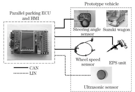
Fig.1 Configuration of the parallel parking system
At the beginning, the driver presses down the parking assist system start button on the HMI, and the ECU changes the system into the ready state. Then, the ultrasonic sensors start to detect the parking space. The ECU calculates the parking space using the information from the ultrasonic sensors and the wheel speed sensors. If the parking space satisfies the requirement of parallel parking, the environment model is constructed by the ECU. After that, the path planning module generates a collision-free path based on the starting position. Finally, the path tracking module controls the vehicle to follow the designed path.
2 Vehicle kinematics and path planning
2.1 Vehicle kinematics
The vehicle reference position is located at the midpoint of rear axle. The rear wheels are fixed parallel to the longitudinal axis of car body. Suppose that there is a pure rolling contact between the rear wheels and road surface, this ensures that the vehicle speed vector is always tangent to the automobile orientation. The vehicle kinematic model is shown in Fig.2. The parameter specification for the kinematic model is presented in Tab.1.

Fig.2 Kinematic model of the vehicle
Tab. 1 Parameter specification

ParametersDescriptionValue/mmWaVehiclewidth1666WbRearwheeltread1475LfFrontoverhanglength744LrRearoverhanglength585LaVehiclelength3779LbVehiclewheelbase2450RminMinimumturningradius4500
The configuration of the vehicle can be described by four state variables: the reference position coordinates (xr,yr), the vehicle orientation (Φ),andthecurvature(ρ=1/R).Thekinematicsofthevehiclewithrespecttotheaxiscenteroftherearwheelsaredescribedas
(1)
whereVis the vehicle longitudinal velocity;f(V,t) is the parking velocity disturbance;ws(V,t) is the model uncertainty of the steering system kinematics;Lbis the vehicle wheelbase; δrepresentsthefrontwheelsteeringangle; Tsrepresentsthesteeringsystemdelaytime; uisthecommandfrontsteeringangle.
Thecurvatureanditsderivativecanbedescribedas
(2)
Duetothephysicalpropertiesandsteeringmechanicalproperties,thecurvatureρanditschangerateγshouldbelimited,i.e.
(3)
2.2Pathplanning
ParallelparkingprocessconsistsofonestraightlineS0and two circular arcs (S1,S2). In Fig.3, the two black rectangles denote front and rear obstacles, the white rectangle on the right top denotes initial parking position, and the white rectangle on the left bottom denotes the final parking position.S1andS2denote the first and second arcs of the path of the middle point of the rear axle, respectively.

Fig.3 Parallel parking process
The parallel parking process can be described as follows:
(4)
whereR1,R2,S0, θandh0aredefinedinFig.3.Eachvalueoftheparameters[R1, R2, S0]determinesaparallelparkingpath.
Collisionscouldbeavoidedifavirtualvehicleleavestheparkingspacewithoutcollision[9].Finalmanoeuvresareobtainedusingthisdesigninareversesequence.ThegoalpositionDgoisdefinedbythreesafetydistancesDrl, DloandDrrinaparkingspace.ThefirstpossiblecollisionisshowninFig.4.

Fig.4 First possible collision
Inordertodesignthefirstcontinuouscollision-freepath,thedesignedpathshouldavoidthecollisionbetweentherightfrontofvehicleandfrontobstacle.ThemaximumvalueofradiusR1canbecalculatedby
(5)
whereLpdenotes the parking space length,Dfris the safety distance, the other parameters have been defined by Fig.2.
The minimum value of radiusR1is determined by the vehicle physical properties. It can be described as
(6)
TheradiusR1is located betweenR1minandR1max, i.e.
R1∈[R1min,R1max]
(7)
The second possible collision is shown in Fig.5. The designed path should avoid the collision between the vehicle lateral side and the obstacle ahead.

Fig.5 Second possible collision
The maximum value of radiusR2can be obtained by solving the following equations as
(8)
ThelastpossiblecollisionisshowninFig.6.Itrepresentsthecollisionbetweentheleftfrontofvehicleandtheleftobstacleorstreetcenterline.
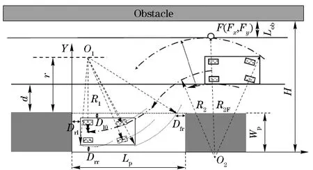
Fig.6 Third possible collision
TheminimumturningradiusR2mincan be calculated by
(9)
whereLobis the safety distance to the opposite obstacle,dis the lateral distance between the ultrasonic sensor and the obstacle,Wpis the parking space width.
The value range of the radiusR2is located betweenR2minandR2max, i.e.
R2∈[R2min,R2max]
(10)
The minimum forward displacementL0minand the maximum displacementL0maxcan be expressed as
(11)
(12)
Eachparameters[R1,R2,L0] determines a parallel parking manoeuvre. Different manoeuvres under different forward displacements are shown in Fig.7.

Fig.7 Different parallel parking manoeuvres
3 ADRC controller design
The focus of this research is to design a robustness path tracking controller, which can precisely control vehicle to follow the ideal parking path in spite of existing uncertainty and disturbances in the system. If the system exists model uncertainty, external disturbance and sensor noises, the traditional controller cannot reach the design objectives[10-11]. In this section, a path tracking controller based on ADRC is developed, which can estimate and compensate the influence generated by the model uncertainty and disturbances in real time.
3.1 Tracking differentiator
The ADRC controller is composed of a tracking differentiator (TD) which is in the feedforward path, an extended state observer (ESO) and a nonlinear state error feedback (NLSEF) control law in the feedback path. The structure diagram of second order ADRC is shown in Fig.8. The TD process is adopted in ADRC for transient process and command signal generation. The TD in the feedforward path is used to replace the PID differential component, which can improve the system effectiveness and robustness performance when the system suffers sensor noise and external disturbances.

Fig.8 Second order ADRC structure
The employment of TD can yield fast tracking without overshoots, while simultaneously avoiding the rapid fluctuations of the control signal. The definition of TD process can be expressed as
(13)

(14)
3.2Extendedstateobserver
AsshowninFig.8,theESOcanestimatethechangerateandthetotaldisturbanceoferror,whichisbasedonthecontrolvariablesandinputsignalerrors.TheESOcanbeseenasasoftsensor,whichcanmeasurethecontrolsystemunknowndisturbance[12].Thedynamicfeedbackcompensationcanbeconductedproperlyusingestimatedtotaldisturbances[13-15].Thirdorderextendedstateobservercanbedescribedas
(15)
wherex1(k),x2(k) andx3(k) are the outputs estimated by ESO,x1(k) represents the tracking signal ofy(k),x2(k) is the first derivative ofx1(k), which is the velocity of tracking signal,x3(k) represents the estimated total disturbances.
The nonlinear functionfal(e(k),a,δ)canbeexpressedas
fal(e(k),a,δ)=
(16)
wherea1,a2, δandb0arethedesignparameters, β01, β02andβ03arethegainsofESOandcanbedeterminedby[16]
(17)
3.3Nonlinearstateerrorfeedbackcontroller
TheNLSEFcontrollerisanonlinearPDcontroller,whichcanbedescribedas
(18)
whereβ1, β2, α01, α02andδ0arethedesignparameters.
Thecontrollawu0isanonlinearcombinationoferrore1anddifferentialerrore2.Inordertocancelouttheunknowndisturbancesbeforetheydegradethesystemperformance,thetotalactualcontrolvariablesappliedtotheactuatorofthecontrolsystemcanbeexpressedas
u(k+1)=u0(k+1)-x3(k+1)/b0
(19)
3.4 Path tracking controller design
The path tracking can be seen as a preview follower process, which is described in Fig.9. The target of path tracking is to control the displacement errorΔyandtheorientationerrorΔΦofthevehicle.ThelongitudinalvelocityVofthevehicleisperpendiculartothevehiclerearaxle, LrepresentsthepreviewdistanceandTdenotesthepreviewtime.

Fig.9 Preview follower in parallel parking
ThelateraldisplacementerrorΔyandtheorientationerrorΔΦcanbededucedas
(20)
where(x0,y0, Φ0)describesthecurrentpositionandorientationofvehicle, VxandVydenotethevelocitycomponents, f(x)isthereferencepath.
ThetargetofADRCcontrolleristocontroltheerrorztozero,whichiscomposedbythelateraldisplacementerrorΔyandtheorientationerrorΔΦ.Theerrorzcanbedescribedby
z=c1tanh (c0Δy)+Δφ
(22)
wherec0andc1are positive parameters, tanh represents hyperbolic tangent function. The astringency of the nonlinear equation can be proved by the Lyapunov function.
The designed path tracking controller based on ADRC is shown in Fig.10. Wherev0is the desired signal, here, the purpose of ADRC path tracking controller is to control the errorzto track the signalv0, so the value ofv0is determined asv0=0;z1represents the tracking signal ofz;z2is the first derivative ofz1, which is the velocity of tracking signal;z3denotes the estimated total disturbances.

Fig.10 Path tracking controller based on ADRC
4 Simulation and real vehicle tests
4.1 Simulation results and analysis
To investigate the proposed path tracking controller, different simulation conditions considering the model uncertainties and disturbances are used to verify the robustness and effectiveness of path tracking controller. The model uncertainty of steering kinematics due to the complex mechanism can be described as a function of longitudinal velocity and time, which can be supposed asws(V,t)=0.02Vsin(5t). Considering the effect due to road disturbance such as road bumps, the external disturbancef(V,t) can be described asf(V,t)=Vsin(8t). The steering system delay described in Eq.(1) can be seen as a system internal disturbance, the delay time of steering systemTScan be defined asTS=0.5 s.
The parameters (Tab.2) for ADRC controller and PID controller are determined using optimization methods.

Tab.2 Parameters for ADRC and PID controllers
The simulation results are shown as follows. The parking speed is shown in Fig.11, where the longitudinal velocityVis 1 m/s, the external disturbancef(V,t) changes as sine wave with time. The path tracking performance can be seen from Fig.12. The solid line represents the predetermined reference path, the dashed line describes the tracking path controlled by ADRC method, and the dotted line shows the tracking path controlled by PID method. From Fig.12, it can be seen that the path tracking controller based on ADRC gives superior performance to the conventional PID controller.

Fig.11 Parking speed (V=1 m/s)

Fig.12 Tracking performance comparison between PID and ADRC
The ADRC controller contains an extended state observer (ESO), which can estimate the total disturbances and compensate the disturbances before the disturbances affect the controlled plant. The total disturbances estimated by ESO are shown in Fig.13.

Fig.13 Estimated total disturbance z3
The parking speed is measured by the wheel speed sensor, while the wheel speed sensor signal is vulnerable to outside world electromagnetic interference and the wheel speed detection device is easy to vibrate when vehicle is parking on a bumpy road. For this reason, a white noise occurs in the parking speed, the parking speed detected in the experiments is shown in Fig.14. In the following simulation studies, the parameters for PID and ADRC controllers remain the same as described in Tab.2, respectively. Fig.15 shows that the path tracking performance comparison between the PID controller and ADRC controller. The solid line is the desired path, the dashed line describes the tracking path controlled by ADRC method, and the dotted line shows the tracking path controlled by PID method. It can be observed that the ADRC method can effectively control vehicle to track the desired path even though vehicle suffers to external disturbances, while the PID controller cannot effectively track the desired path. The simulation result shows that the ADRC parameters are robust to external disturbances, but the PID parameters need to be constantly adjusted to resist the external disturbances. The PID method aggravates the burden of engineers for its parameters adjustment. The ADRC controller can use the ESO to estimate the system uncertainties and total disturbances, which is shown in Fig.16.

Fig.14 Experimental parking speed

Fig.15 Tracking performance comparison between PID and ADRC

Fig.16 Estimated total disturbances z3
4.2 Real vehicle tests
To verify the performance of proposed path tracking controller, the parallel parking system controller is equipped on a prototype vehicle.A ComNav RTK GNSS differential global positioning system (DGPS) is used to measure the actual motion path of a vehicle. The DGPS can provide the position and orientation information. The position accuracy is around 1 cm and the orientation accuracy is around 0.1°. The data update rate of position and orientation is 200 ms. In Fig.17, the parking space is measured by the ultrasonic sensors and wheel speed sensors, the length of parking space is around 6 m, the width is around 2.5 m. The solid line describes ideal path and the dashed line represents actual motion path. In order to calculate the average lateral displacement error in the whole parallel parking, ten waypoints located on the ideal path and the actual path are recorded. In Tab.3, (X,Yid) and (X,Yac) represent the ideal and actual waypoints, respectively. The average value of lateral displacement error is 0.067 7 m. The maximum value of lateral displacement error is 0.11 m. The vehicle can be precisely controlled to track the ideal path without collision with the surrounding obstacles.

Fig.17 Actual path and ideal path comparison
Tab.3 Lateral displacement error
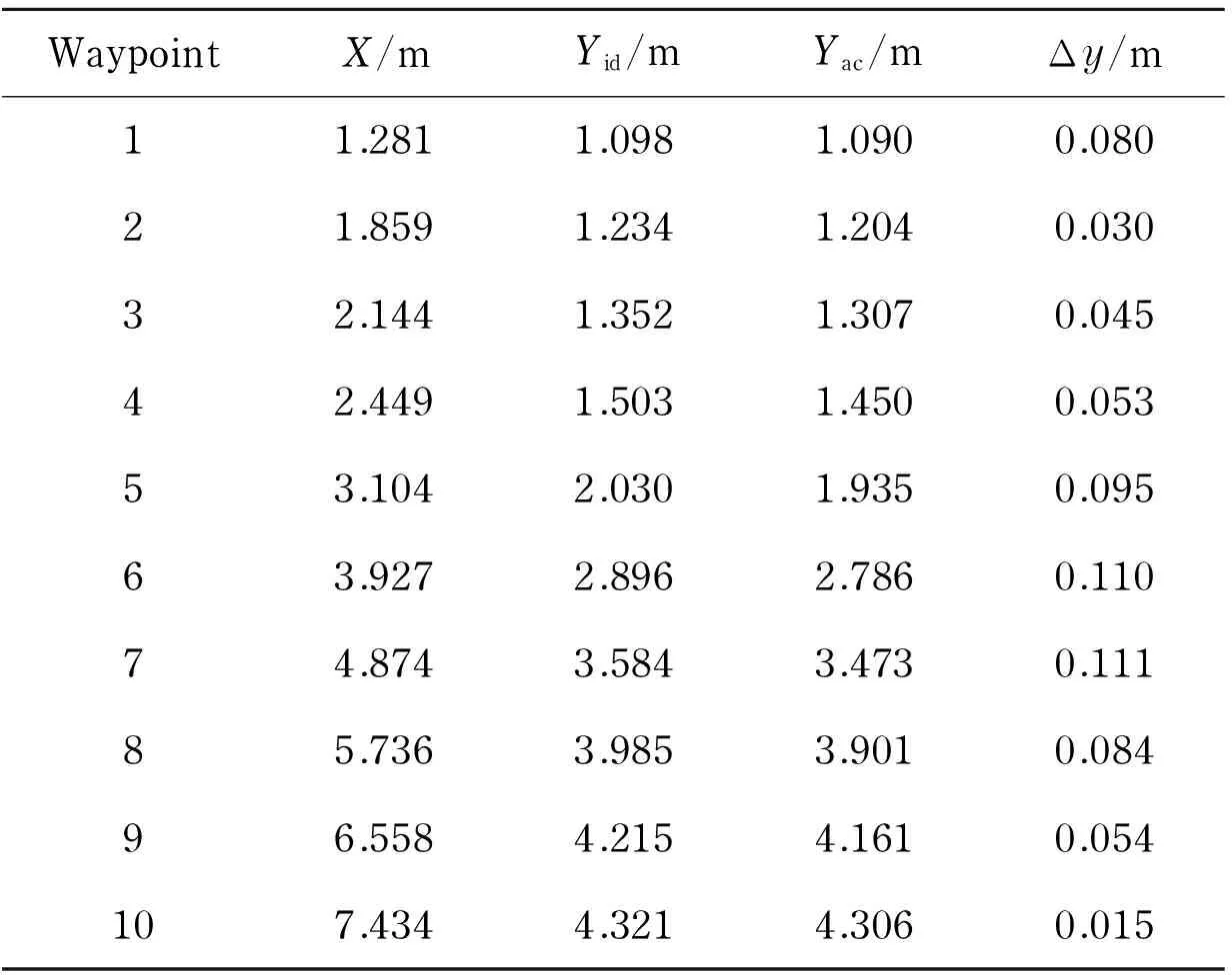
WaypointX/mYid/mYac/mΔy/m11.2811.0981.0900.08021.8591.2341.2040.03032.1441.3521.3070.04542.4491.5031.4500.05353.1042.0301.9350.09563.9272.8962.7860.11074.8743.5843.4730.11185.7363.9853.9010.08496.5584.2154.1610.054107.4344.3214.3060.015
5 Conclusion
A novel path tracking controller based on ADRC method was proposed to improve the robustness of path tracking. The extended state observer (ESO) effectively estimated the total disturbances, such as steering system modeling imprecision, parking speed disturbance and steering system delay disturbance. The ADRC controller had estimated and compensated the total disturbances before the disturbances affected the controlled plant, while the PID controller began to work after the disturbances had influenced the controlled plant. The path tracking results show that the control effectiveness of ADRC controller was much better than conventional PID controller, the ADRC technique gave noticeably better results in terms of parametric robustness than PID. The real vehicle tests verify the effectiveness of path tracking controller. In the near future, the proposed path tracking method can be used in intelligent driving area.
[1] Huang S J, Lin G Y. Parallel auto-parking of a model vehicle using a self-organizing fuzzy controller [J]. Journal of Automobile Engineering, 2010, 224(8): 997-1012.
[2] Liu Yahui, Ji Xuewu, Ryouhei H, et al. Function of shoulder muscles of driver in vehicle steering maneuver [J]. Science China Technological Sciences, 2012, 55(12): 3445-3454.
[3] Lee C K, Lin C L, Shiu B M. Autonomous vehicle parking using hybrid artificial intelligent approach [J]. Journal of Intelligent and Robotic Systems, 2009, 56:319-343.
[4] Zhao Y N, Collins Jr E G. Robust automatic parallel parking in tight spaces via fuzzy logic [J]. Robotics and Autonomous Systems, 2005, 51(2):111-127
[5] Demirli K, Khoshnejad M. Autonomous parallel parking of a car-like mobile robot by a neuro-fuzzy sensor-based controller [J]. Fuzzy Sets and Systems, 2009, 160(19): 2876-2891.
[6] Lian K Y, Chiu C S, Chiang T S. Parallel parking a car-like robot using fuzzy gain scheduling [C]∥IEEE International Conference on Control Applications, Hawai, USA, 1999.
[7] Ollero A, García-Cerezo A, Martínez J L, et al. Fuzzy tracking methods for mobile robots [J]. Applications of Fuzzy Logic: Towards High Machine Intelligence Quotient Systems, 1997, 9: 347-364.
[8] Han Jingqing. From PID technique to active disturbances rejection control technique [J]. Control Engineering of China, 2002, 9(3):13-18. (in Chinese)
[9] Gómez-Bravo F, Cuesta F, Ollero A, et al. Continuous curvature path generation based on βsplinecurvesforparkingmanoeuvres[J].RoboticsandAutonomousSystems, 2008, 56(4): 360-372.
[10]YuGR,HwangRC.OptimalPIDspeedcontrolofbrushlessDCmotorsusingLQRapproach[C]∥IEEEInternationalConferenceonSystems,Man,andCybernetics,Hague,Netheirlands, 2004.
[11]ZhaoWanzhong,LinYi,WeiJianwei,etal.Controlstrategyofanovelelectricpowersteeringsystemintegratedwithactivefrontsteeringfunction[J].ScienceChinaTechnologicalSciences, 2011, 54(6):1515-1520.
[12]SuYX,DuanBY,ZhengCH,etal.Disturbance-rejectionhigh-precisionmotioncontrolofastewartPlatform[J].IEEETransactionsonControlSystemsTechnology, 2004, 12(3):364-374.
[13]JeongJW,ChangPH,ParkKB.Sensorlessandmodelessestimationofexternalforceusingtimedelayestimation:applicationtoimpedancecontrol[J].JournalofMechanicalScienceandTechnology, 2011, 25(8): 2051-1059.
[14]LiSL,YangX,YangD.Activedisturbancerejectioncontrolforhighpointingaccuracyandrotationspeed[J].Automatica, 2009, 45(8):1854-1860.
[15]HanDK,ChangP.Robusttrackingofrobotmanipulatorwithnonlinearfrictionusingtimedelaycontrolwithgradientestimator[J].JournalofMechanicalScienceandTechnology, 2010, 24(8):1743-1752.
[16]HanJQ.FromPIDtoactivedisturbancerejectioncontrol[J].IEEETransactionsonIndustrialElectronics, 2009, 56(3): 900-906.
(Edited by Cai Jianying)
10.15918/j.jbit1004- 0579.201524.0212
U 471.15 Document code: A Article ID: 1004- 0579(2015)02- 0213- 09
Received 2014- 05- 08
Supported by the National Natural Science Foundation of China (11072106,51005133,51375009)
E-mail: yqzhao@nuaa.edu.cn
猜你喜欢
清华金融评论(2022年4期)2022-04-13
内燃机与配件(2022年2期)2022-01-17
Chinese Physics B(2021年11期)2021-11-23
江苏通信(2021年1期)2021-05-31
抗癌之窗(2020年1期)2020-05-16
百花园(2019年6期)2019-09-10
艺术品鉴(2017年8期)2017-09-08
南风窗(2017年9期)2017-05-04
检察风云(2016年12期)2016-09-10
老年教育(老年大学)(2016年6期)2016-04-14
 Journal of Beijing Institute of Technology2015年2期
- Journal of Beijing Institute of Technology的其它文章
- Nonlinear symbolic LFT model for UAV
- Novel scheme of high precision inertial measurement for high-speed rotating carriers
- Study on influencing factors of adapters separating with the underwater missile
- Fast-solving method for air-to-surface guided bombs’ allowable attack area
- Design and analysis of mechanical self-destruction and self-neutralization mechanism for submunition fuze
- Resilience approach for heterogeneous distributed networked unmanned weapon systems