
Novel method to calibrate kinematic parameters for mobile robots
2015-04-24 05:30SHIJiadong施家栋LIUJuan刘娟WANGJianzhong王建中
关键词:刘娟
SHI Jia-dong(施家栋), LIU Juan(刘娟), WANG Jian-zhong(王建中)
(Key Laboratory of Biomimetic Robots and Systems, Ministry of Education, Beijing Institute of Technology, Beijing 100081, China)
Novel method to calibrate kinematic parameters for mobile robots
SHI Jia-dong(施家栋), LIU Juan(刘娟), WANG Jian-zhong(王建中)
(Key Laboratory of Biomimetic Robots and Systems, Ministry of Education, Beijing Institute of Technology, Beijing 100081, China)
In order to reduce the system errors of dead reckoning and improve the localization accuracy, a new model for systematic error of mobile robot was defined and a UMBmark-based method for calibrating and compensating systematic error was presented. Three dominant reasons causing systematic errors were considered: imprecise average wheel diameter, uncertainty about the effective wheelbase and unequal wheel’s diameter. The new model for systematic errors is considering the coupling effect of the three factors during the localization of mobile robot. Three coefficients to calibrate average wheel diameter, effective wheelbase, left and right wheels’ diameter were obtained. Then these three coefficients were used to make improvements on robot kinematic equations. The experiments on the dual-wheel drive mobile robot DaNI show that the presented method has achieveda significant improvement in the location accuracy compared with the UMBmark calibration.
odometry; systematic errors; position; calibration; mobile robot
Considering the trajectory of mobile robot in a short time as a small circle or a small straight line, dead reckoning acquires the position of mobile robot through continuous integration. Encoders used in dead reckoning can provide higher positioning accuracy in a short time, which makes it as a most-commonly used positioning method. However, the major drawback of dead reckoning with encoders’ data is accumulation of errors, especially when the robot’s orientation is calculated from the encoders’ data. Positioning errorscan be classified into systematic error and nonsystematic error. Systematic error is mainly caused by the imperfection of robot’s kinemics model, which will not change in long time and will be accumulated over time, even lead to incorrect position. Therefore, measurement and calibration of systematic error is a prerequisite to acquire accurate position of mobile robot.
In the investigations on systematic error of mobile robot, many scholars hold the view that the three domain factors which caused systematic errors are imprecise average wheel diameter, uncertainty about the effective wheelbase and unequal wheel’s diameter[1-2]. Most studies only considered the latter two factors’ as separate influences[1,3-6], but in practice, these two factors will lead to coupling effect when the robot is in a turning or a straight motion[4,7-8]. Moreover, the difference between robot’s actual average wheel diameter and nominal average diameter will produce errors in positioning process[4,9].
In this paper, systematic error of mobile robot is analyzed, and then an improved error model of mobile robot is established.A method to calibrate kinematic parameters for mobile robot is proposed, which is applied to the robotic kinematic model. Finally, the proposed calibration method is experimentally verified on mobile robot DaNI.
1 Analysis of systematic error
Systematic error is usually caused by imperfections in the design and mechanical implementation of a mobile robot. Parts manufacture and assembly of mobile robot make it difficult to ensure the consistency of the left and right wheel diameters. Furthermore,rubber tires compress differently under asymmetric load distribution for its flexibility,which makes the actual left and right wheel diameters of mobile robot are difficult to be the exactly same as nominal diameters used in kinematic model. Moreover, rubber tires contact the floor in a contact area, so the effective wheelbase used in the kinematic model of mobile robot can’t simply use the measured nominal value. Via the analysis above, the main systematic error sources in positioning process of mobile robot are imprecise average wheel diameters, which is denoted byEs; Uncertainty about the effective wheelbase, which is denoted byEb; Unequal wheel diameters, which is denoted withEd.Es,EbandEdare all dimensionless value.
Borenstein[1]analyzed the effect of unequal wheel diameters during on-the-spot turning of mobile robot, and obtained the relation between the nominal rotational angleτnand the actual rotational angleτ.
Da/τ=Dn/τn
(1)
whereDais the average actual diameter of left and right drive wheels,Dnis the average nominal diameter of left and right drive wheels.
An important conclusion can be drawn from Eq. (1). IfDa≠Dn, in other words, whenEs=Da/Dn≠1, there will be orientation error during on-the-spot turning of mobile robot.
Borenstein[1], Lee[7]and Jung[8]found that the average actual diameter of left and right drive wheels was easy to calibrate with just an ordinary tape measure. However, if the control accuracy of robot used in experiment is not high,Esobtained from measurement will lead into larger controlling error. The systematic error was calibrated via measuring the robot’s final orientation errors in test track by Bostani[2]and Jung[8]. However, given the limitations of the measurement tool, random error generated from the measurement of small angle is greater than the measurement of distance. Therefore, error from the measurement of small angle will have a greater impact on the calculation ofEs. Abbas[4]and Lee[6]established the error model of mobile robot without considering the effect ofEs,and both of them adopt circular track in their experiments. But in practice, when robot walks along a given circular track, its actual trajectory is not strictly circular, even elliptical. Therefore, there will be a greater error in measuring diameter of the actual path, and this will affect the accuracy of the calculations ofEd.
Through the above analysis, square path can overcome the shortcoming of inaccurate measurement diameter of circular path. There are four 90° turnings in the square path, which make the position errors caused byEscompensate for each other and become negligible. But the orientation errors will be accumulated over time, which affects the effect of calibration. Therefore, the coupled effects amongEs,EbandEdshould be considered when the robot is walking along a straight line or turning on the spot.
2 Improvement of systematic error model
Assumptions for systematic error model:
①Es,EbandEdare the main sources causing systematic error in dead reckoning;
② The orientation errorαof turning is the coupled result ofEs,EbandEd, and it is defined as the first type of error, as show in Fig. 1a;
③ The orientation errorβin straight-line motion is also the coupled result ofEs,EbandEd, and it is defined as the second type of error, as shown in Fig. 1b.
The unequal wheel diametersEdof mobile robot will lead to cured motion when the robot walks in a straight line, as shown in Fig. 1b. The actual incremental travel distanceULandURfor the left and right wheels can be measured with a speedometer. if the increments of left and right encoder pulses areNLandNR, then linear wheel displacement corresponding to single pulse and the actual diameters of left and right wheels can be computed[9], respectively, according to

Fig.1 The first type and the second type of error in CW and CCW path
wherenis the reduction gear between the motor and the drive wheel;Ceis the encoder resolution. The average actual wheel diameter isDa=(DL+DR)/2, then
Es=Da/Dn
(2)
In the square path, the nominal angle of turning on the spot isτn=90°, thus the actual angleτcan be computed asτ=Da/Dnτnfrom Eq.(1). Then the orientation error caused byEsin turning on the spot can be denoted as
αs=τn-τ=90°-τ
(3)
Considering the coupling effect ofEs,EdandEbin turning on the spot, the orientation errorαdcaused by unequal diameters of the left and right wheels can be calculated as follows[3]:
(4)
wherebnis nominal wheelbase;Lis length of desired square path.
The total orientation errorαandβcaused byEs,EbandEdcan be obtained from gradually calculating the final position (x4,y4) and the start position (x0,y0)[1].
Fig.1a and Fig.1b show the first type of errorαcaused byEs,EbandEdin clockwise (CW) and counterclockwise (CCW) square paths, thus the end positions of CW and CCW paths are (x4,y4)=(-2Lα,-2Lα) and (x4,y4)=(-2Lα,2Lα), respectively. Equivalently, according to the second type of errorβin Fig.1c and Fig.1d caused byEs,EbandEdin CW and CCW square paths, the end positions of CW and CCW paths are (x4,y4)=(-2Lβ,-2Lβ) and (x4,y4)=(2Lβ,-2Lβ) can be calculated respectively.
Superimposing the first type and the second type of error for the CW and CCW experiments inx- ory-direction, and then yields
(5)
or
(6)
wherexc.g.CW/CCWandyc.g.CW/CCWare the coordinates of two error centres, and can be computed by Ref.[1].
According to Eqs.(3)(4), the orientation errorαbcaused by uncertain wheelbaseEbcan be derived as follows.
αb=α-(αs+αd)
(7)
Therefore, the error model of mobile robot can be denoted as follows.
(8)
whereRis the curvature radius of the cured path;bais actual wheelbase.
3 Calibration of kinematic parameters
A dual-wheel differential drive mobile robot DaNI is utilized in the experiment as shown in Fig.2. Two front wheels are the left and right drive wheels, rear wheel is the auxiliary wheel. The kinematic model of mobile robot is established based on the following assumptions.
①Structure of the robot is rigid, and the two wheels have the same diameter;
②There is only pure rolling around the axis of wheel without sliding axially, and in the process of movement, wheel and the ground are always perpendicular to each other;
③Robot’s movement is in the plane.
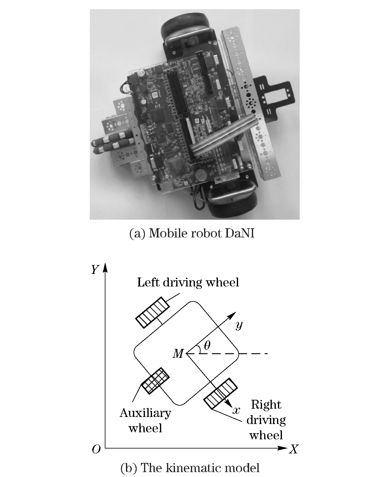
Fig.2 Structure diagram of mobile robot
The trajectory of mobile robot in a short time can be considered as a small circle or a small straight line, as shown in Fig.3.
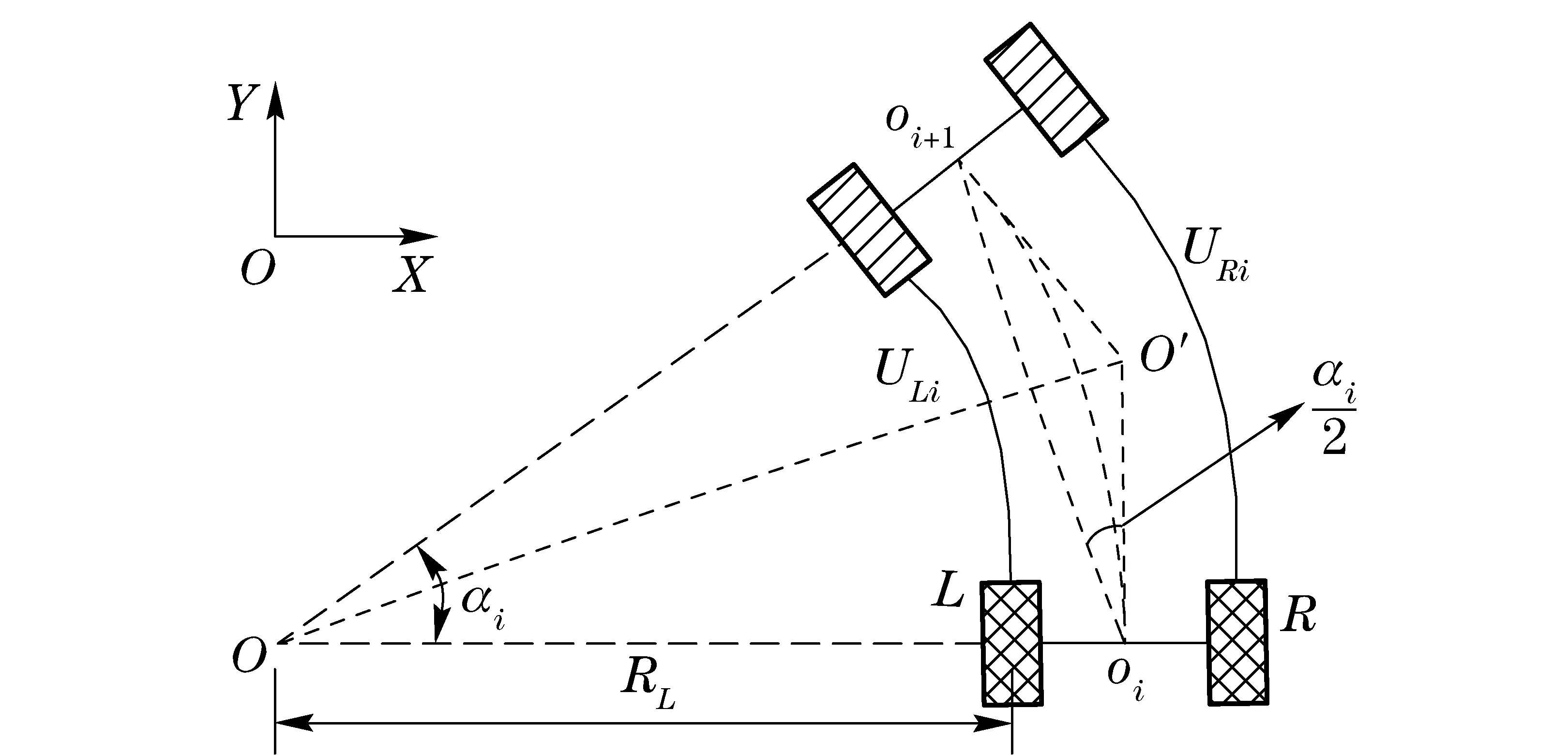
Fig.3 Trajectory of mobile robot
According to assumption (2), there is no wheel slippage, so parametersRLandαiof the trajectory are
(9)
wheretis the sampling interval;ULiandURiare incremental travel distances of left and right wheels int;ωLandωRare the speeds of left and right wheels;rnis the nominal average radius;bnis nominal wheelbase;RLis the distance between the center of trajectory and the left wheel;αiis the central angle in the sampling intervalt;
In Fig.3,Oiis the midpoint of robot’s axle at timei. LineOiOi+1=2(R+b/2)sin (αi/2) and its coordinates areOi(px,i,py,i) andOi+1(px,i+1,py,i+1).θiis the robot’s orientation in the global coordinate systemOXY. Therefore, the poses of robot at timei+1 can be derived from robot’s pose at timei,
(10)
If the robot walks in a straight line, its kinematic model is as follows
(11)
According to Eq.(8), the calibrated kinematic parameters of mobile robot can be obtained as
(12)
whererLandrRare the actual radii of left and right wheels;rais the actual average radius. Therefore, the parameters are changed into
(13)
Substituting the calibrated kinematic parameters (12) in the kinematic model of mobile robot, and then
①When the robot walks in a straight line
(14)
②When the robot walks in a curve
(15)
4 Experiment and analysis of results
The experimental robot DaNI is programmed to traverse the four legsof the 3×3 m square path for 5 times with 0.2 m/s in both clockwise and counterclockwise directions. In order to avoid slippage, the robot makes a on-the-spot 90° turning with 0.785 rad/s on the inflection of square path. The final position errors of robot before and after the calibration of kinematic parameters are showed in Fig.4.
Fig.4a is the experimental results of uncalibrated and UMBmark. Fig.4b is the comparison result between UMBmark and proposed method. The calibration parameters and systematic error of the two calibration method are shown in Tab.1.
Emax,systrepresents the systematic error, which is defined in Ref.[1].As shown in Tab.1, the systematic errorsEmax,systis 372.685 mm before calibration and 69.001 mm after UMBmark calibration, this represents a 5.401-fold improvement in the positioning accuracy. However, the proposed method enables systematic error further reduced to 33.73 mm, and the positioning accuracy is increased by 11.409-fold.

Fig.4 Final position error after navigating square path
Tab.1 Calibration parameters and systematic errors
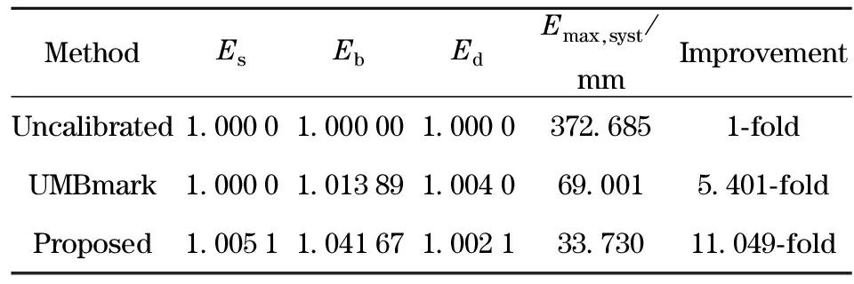
MethodEsEbEdEmax,syst/mmImprovementUncalibrated1 00001 000001 0000372 6851⁃foldUMBmark1 00001 013891 004069 0015 401⁃foldProposed1 00511 041671 002133 73011 049⁃fold
5 Conclusion
This paper considers systematic errors caused by imprecise average wheel diameter, uncertain effective wheelbase and unequal wheel’s diameter. On the assumptions that the first type of error and the second type of error are all coupling results ofEs,EbandEd, a improved systematic error model of mobile robot is established, and then a method to calibrate kinematic parameters for mobile robot is proposed, which is experimentally verified on the mobile robot DaNI in experimental square paths. The results show that the proposed method enables the positioning accuracy of mobile robot increased by about 10 times.
[1] Borenstein J, Feng L. Measurement and correction of systematic odometry errors in mobile robots[J].IEEE Transactions on Robotics and Automation,1996,12(6):869-880.
[2] Bostani A, Vakili A, Denidni T A. A novel method to measure and correct the odome-try errors in mobile robots [C]∥Canadian Conference on Electrical and Computer Engineering,2008: 855-858.
[3] Maddahi Y, Sepehri N, Maddahi A,et al. Calibration of wheeled mobile robots with differential drive mechanisms:an ex-perimental approach[J]. Robotics,2012,30(6):1029-1039.
[4] Tanveer Abbas, Muhammod Arif, Waqas Ahmed, et al. Measurement and correction of systematic odometry errors caused by kinematics imperfections in mo-bile robots [C]∥SCIE-ICASE International Joint Conference,2006:2073-2077.
[5] Borenstein J, Feng L. UMBmark: a benchmark test for measuring odometry errors in mobile robots[J]. SPIE Conference on Mobile Robots,1995,2591:113-124.
[6] Lee Kooktae, Chung Woojin. Calibration of kinematic parameters of a car-like mobile robot to improve odometry accuracy [C]∥2008 IEEE International Conference on Robotics and Automation,2008:2546-2551.
[7] Lee K,Jung C, Chung W. Accurate cali-bration of kinematic parameters for two wheel differential mobile robots [J]. Journal of Mechanical Science and Technology,2011,25(6):1603-1611.
[8] Jung C, Chung W. Accurate calibration of two wheel differential mobile robots by using experimental heading errors[C]∥2012 IEEE International Conference on Robotics and Automation,2012:4533-4588.
[9] Wang Weihua,Xiong Youlun, Sun Ronglei. Measurement and calibration of correction of systematic odometry errors [J]. Robotics,2004,26(5):454-460.(in Chinese)
(Edited by Wang Yuxia)
10.15918/j.jbit1004-0579.201524.0113
TP 242 Document code: A Article ID: 1004- 0579(2015)01- 0091- 06
Received 2013- 08- 15
Supported by Basic Research Foundation of Beijing Institute of Technology (20130242015)
E-mail: sjd215@bit.edu.cn
猜你喜欢
中国药学药品知识仓库(2022年1期)2022-03-23
中华养生保健(2021年18期)2021-02-13
中国商人(2019年9期)2019-09-05
中国商人(2019年9期)2019-09-05
故事会(2018年19期)2018-10-11
共产党员·上(2016年1期)2016-05-01
共产党员(辽宁)(2016年1期)2016-03-15
唐山文学(2015年1期)2015-11-17
微型小说选刊(2015年2期)2015-11-17
故事会(2014年19期)2014-09-25
 Journal of Beijing Institute of Technology2015年1期
- Journal of Beijing Institute of Technology的其它文章
- Numerical simulation of the delay arming process of initiating explosive brakes
- Optimized design of biconical liner by orthogonal method
- Wideband acoustic source localization using multiple spherical arrays: anangular-spectrum smoothing approach
- Influence of eddy current on transient characteristics of common rail injector solenoid valve
- Designing the cooling system of a hybrid electric vehicle with multi-heat source
- Novel miniature pneumatic pressure regulator for hopping robots