
Efficient flutter prediction based on Harmonic Balance and V-g methods
2016-04-01 07:26LiuNanBaiJunqiangLiuYanHuaJun
空气动力学学报 2016年5期
Liu Nan,Bai Junqiang,*,Liu Yan,Hua Jun
(1.School of Aeronautics,Northwestern Polytechnical University,Xi’an 710072,China;2.China Aeronautical Establishment,Beijing 100012,China)
Efficient flutter prediction based on Harmonic Balance and V-g methods
Liu Nan1,Bai Junqiang1,*,Liu Yan1,Hua Jun2
(1.School of Aeronautics,Northwestern Polytechnical University,Xi’an 710072,China;2.China Aeronautical Establishment,Beijing 100012,China)
An efficient flutter prediction method is proposed and applied in the analysis of transonic flutter boundary and influences of structural parameters.Based on frequency domain flutter analysis V-g method,an artificial damping term is applied to aeroelastic system to maintain harmonic motion.Thus,the frequency domain structural dynamic equations can be obtained.The aerodynamic describing function matrices can be acquired efficiently by harmonic balance method at a variety of harmonic frequencies.Combining aerodynamic describing function matrices and frequency domain structural equations,the aeroelastic stability problem can be transferred into a generalized eigenvalue problem.It is demonstrated that the flutter boundary of this method conforms with high-fidelity time-marching method and the analysis efficiency improves significantly.Moreover,when the structural parameters change,new flutter boundary can be easily obtained by generalized eigenvalue analysis in this method,other than time-marching method which needs numerous CFD/CSD coupled simulations.
flutter;frequency domain;harmonic balance;aerodynamic describing function;timemarching method
0 Introduction
Flutter is a typical dynamic aeroelastic phenomenon,which could cause catastrophic results.Transonic flutter prediction is greatly important for the design of transport aircrafts and fighters.Nowadays, Computational Fluid Dynamics(CFD)has been widely applied in transonic flutter predictions[1].However,it is still very time-consuming to calculate instantaneous response of aeroelastic system by time-marching methods.However,it is still very time-consuming to calculate instantaneous response of aeroelastic system by time-marching methods.
To improve analysis efficiency,reduced order model has been widely applied in flutter analysis.Weiwei Zhang et al[2]applied ARX reduced order model to construct aeroelastic equation in state space form,which shows similar results with CFD/CSD simulation,except for transonic condition.Walter A.Silva[3]created multiple-input multiple-output reduced order aeroelastic system based on Volterra series,which established the relationship between modal inputs and generalized aerodynamic forces(GAFs).However,the precision of unsteady aerodynamic forces based on Volterra series is very sensitive to amplitude of input signals and time steps[4].Weiwei Zhang et al[5]also predicted flutter boundary by nonlinear ROM based on RBF neural network model.
Except for the time domain method,frequency domain method is another important approach of flutter analysis[6].Aerodynamic describing functions can be obtained by exciting aeroelastic system with harmonic disturbance of small amplitudes.Then,flutter velocity and frequency of different structural parameters can be obtained by V-g or P-K method,which shows great efficiency,comparing with time-marching methods[7].However,it takes excessive computational costs to calculate harmonic responses of aeroelastic system,because it needs to carry on unsteady flow simulation for each structural mode every harmonic frequency.
In addition,harmonic balance(HB)method shows superior efficiency in the simulation of periodic unsteady flow[8-10],which is widely applied in the simulation of turbomachines[11-12],helicopter rotors[13-14],dynamic derivations[15],et al.Therefore,a frequency domain flutter analysis method based harmonic balance is proposed in this paper,which takes efficiency and precision into account.
1 Time-marching method
Reynolds-Averaged Navier-Stokes(RANS) equation is the highest-fidelity flow solver in current engineering applications,which can be written as:
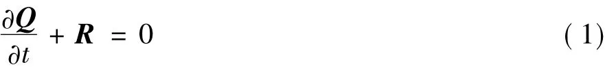
where Q and R are the vectors of flow variables and residuals respectively.Third-order Roe scheme is applied in spatial discretization,while approximate factorization scheme is used in implicit time-marching method.And S-A turbulence model is adopted.
Two-degree-of-freedom structural dynamic equation can be written as:
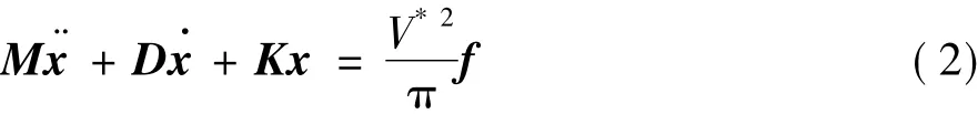
where
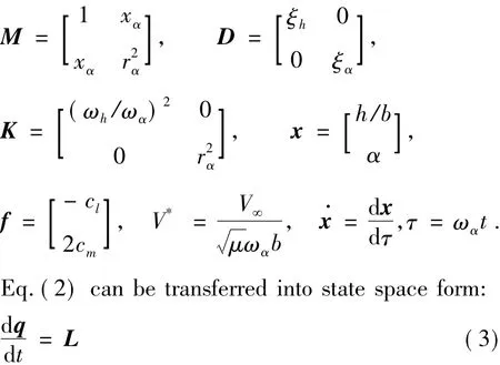
where
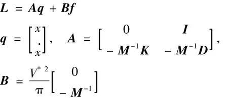
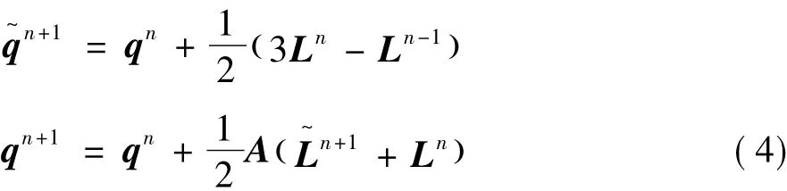
Eq.(3)can be solved by second-order Euler prediction-correction method:
The flow chart of time-marching approach of aeroelastic system is shown in Fig.1.
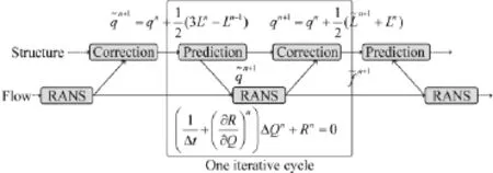
Fig.1 Flow chart of time-marching m ethod of aeroelastic system图1气动弹性系统时间推进求解的流程
2 Harmonic balance method
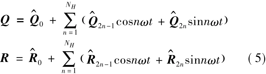
Harmonic balance method is an efficient approach of periodic unsteady flow field.Because of the periodicity,the vector of flow variables and residuals can be deployed by Fourier series:
The time derivation of Q is:

Substituting Eq.(5)into Eq.(1)and rearranging,we can get a pair of algebraic equations:
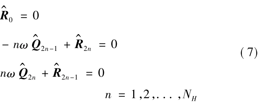
Eq.(7)can be written into matrix form:

where
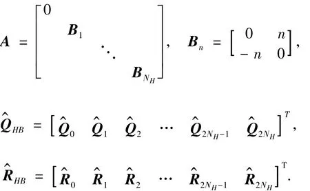
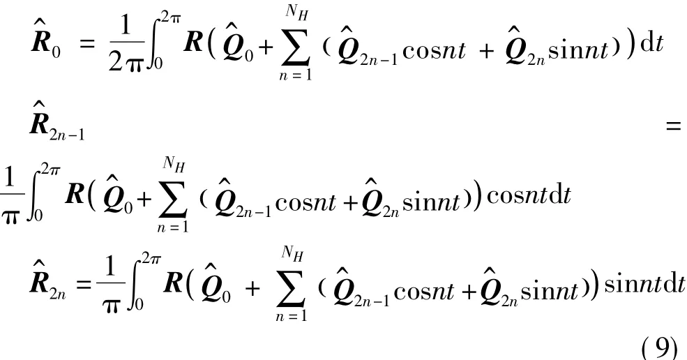
Eq.(8)is the governing equation of original harmonic balance method.In this method,the calculation of residual terms by Fourier transformation is very complex and tedious,which is as follows:
To resolve this problem,sub-time levels were introduced by Hall et al[11]to convert Q back to time domain through Fourier transformation:

where
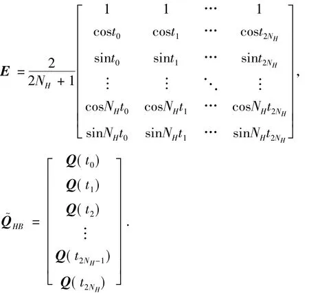
{ti,i=1,2,...,2NH}are equally distributed sub-time levels in a cycle,and ti=2π(i-1)/2NH.
Substituting Eq.(10)into Eq.(8):

Both sides in Eq.(11)are multiplied by E-1:

To achieve an easy approach,the residual terms are simplified by:

where

In this step,nonlinear residual terms can produce terms whose frequencies are higher that NHω,which are included in low-frequency terms by Eq.(13).This rough simplification may produce non-physical solutions in strong nonlinear problems[16].Therefore,the number of harmonics should be chose adequately to guarantee that high-frequency harmonic terms approach zero.Finally the governing equation of harmonic balance method can be obtained:

In order to solve Eq.(14)by time-marching method,pseudo time derivation is added:
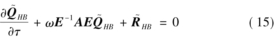
Eq.(15)is the same as original RANS Eq.(1),except for its middle term(which is also called harmonic balance source term).Therefore,harmonic balance solver can be obtained from original steady RANS solver.
Then the harmonic balance method is validated by NACA64A010 airfoil under forced harmonic motion[17].The angle of attack changes as follows:

The flow conditions of two test cases are shown in Table 1.The comparison of unsteady aerodynamic forces between harmonic balance and time-marching methods are illustrated in Fig.2 and Fig.3.It is demonstrated that the unsteady forces calculated by harmonic balance and time-marching methods coincide with each other,which validates the precision of harmonic balance method.The time costs of time-marching and harmonic balance methods are shown in Table 2.
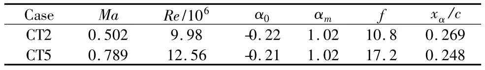
Table 1 Flow condition of NACA64A010 under forced motions表1 NACA64A010强迫运动算例的来流条件
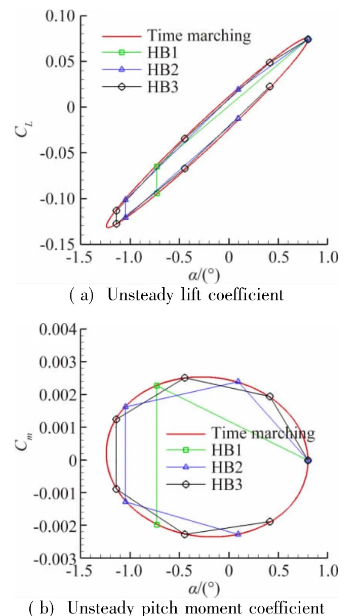
Fig.2 Com parison of unsteady aerodynam ic forces between time-marching and harmonic balance methods in CT2 case图2 CT2算例时间推进和谐波平衡方法计算结果对比


Fig.3 Com parison of unsteady aerodynam ic forces between time-marching and harmonic balance methods in CT5 case图3 CT5算例时间推进和谐波平衡方法计算结果对比
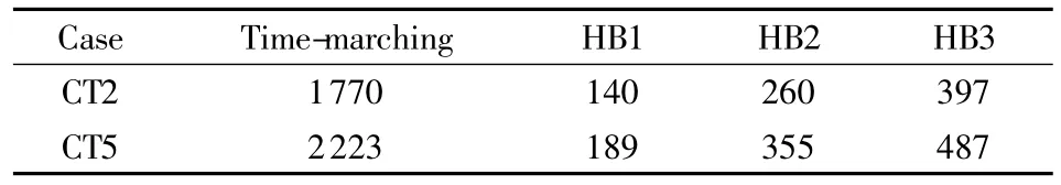
Table 2 Time costs of time-marching and harmonic balance methods(unit:s)表2时间推进和谐波平衡方法计算时间对比(单位:s)
3 Frequency domain solver

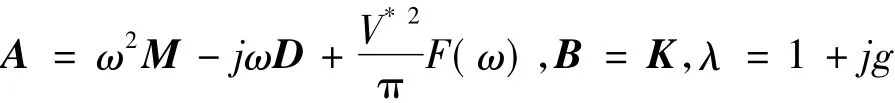
The corresponding lift and pitch moment coefficients can be written as:

Therefore,the structural Eq.(2)can be transferred into frequency domain:

When the aeroelastic system is undergoing single harmonic motion,the plunge and pitch displacements can be written as:
Through aerodynamic describing function matrix F,the aerodynamic forces can be easily obtained by:

where

The aerodynamic describing functions can be obtained through exciting aeroelastic system by harmonic disturbance of small amplitude.Harmonic Balance method is applied to acquired aerodynamic describing functions efficiently.
However,the aeroelastic systemmay exhibit different behaviors(convergent oscillation,simple harmonic or divergent oscillation)in different freestream condi-tions.Therefore,an artificial damping coefficient j g K can be added into the aeroelastic system(19)to maintain harmonic motion:
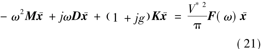
The stability of aeroelastic system can be judged by the sign of artificial damping coefficient.Eq.(21)can be rearranged into a generalized complex eigenvalue problem:

where
At a fixed frequency ω,the matrix A will only change with freestream velocity.Different eigenvalue λ can be obtained in various velocity.When the real part of eigenvalue λReis equal to 1.0,the imaginary part of eigenvalue λImis the damping coefficient at a certain velocity.Thus we can get the relationship between damping coefficients and frequencies(or velocities).When damping coefficient is equal to 0,the frequency and velocity is flutter frequency and velocity respectively.
The procedure of frequency domain flutter analysis is as follows:
1)Calculate aerodynamic forces when the system are undergoing harmonic motionsat different frequencies;
2)Obtain aerodynamic transfer function matrix;
3)Construct generalized complex eigenvalue problem by aerodynamic transfer function matrix and structural dynamic equation;
4)Get the freestream velocity which makes the real part of eigenvalue λRe=1;
5)Obtain the relationship between damping coefficients and frequencies/velocities;
6)Acquire the flutter velocity and frequency.
4 Flutter analysis of Isogai wing
The Isogai Case A wing[18-19]is a standard configuration of flutter analysis.The structural parameters of this case are:xα=1.8,r2α=3.48,a=-2.0,ωh=ωα=100 rad/s,μ=60.The inviscid flutter velocity boundary shows a“S”shape in transonic Mach number,while the viscous flutter velocity boundary does not.
4.1 Aerodynamic describing function matrix
The aerodynamic describing function matrix is calculated byharmonic balance method to improve efficiency.Take h-/b=0.001 and ω=0.10 as an example.Tables 3 and 4 are the lift describing functionsand pitch moment describing functionsat two Mach number (Ma=0.60 and Ma=0.87)respectively.
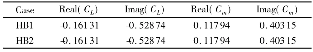
Table 3 Aerodynam ic describing functions at Ma=0.60表3 Ma=0.60时的气动描述函数
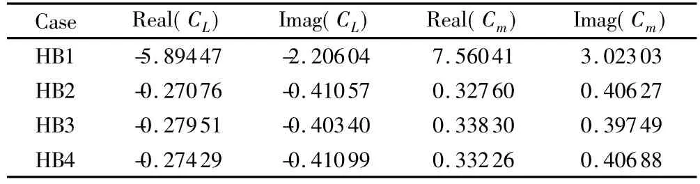
Table 4 Aerodynam ic describing functions at Ma=0.87表4 Ma=0.87时的气动描述函数
It is illustrated that first-order harmonic is enough for subsonic case and more harmonics are necessary for transonic case to ensure the precision of aerodynamic describing functions.
4.2 Flutter boundary
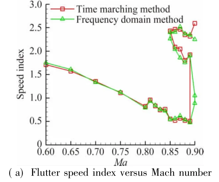
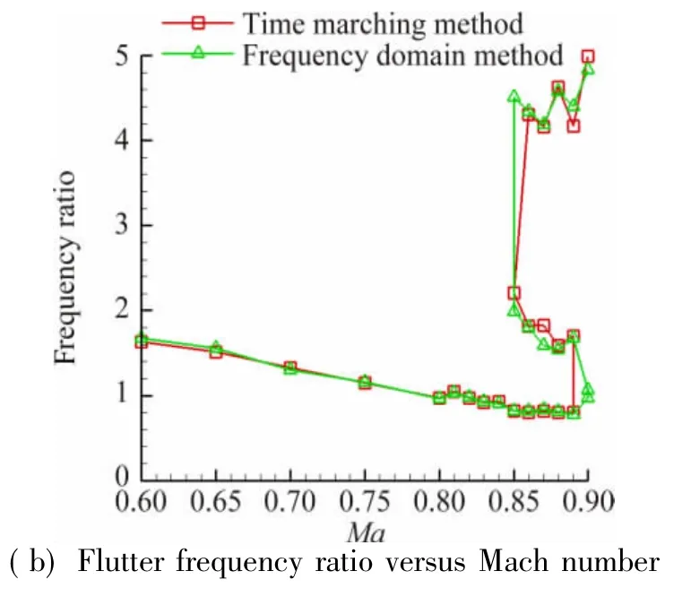
Fig.4 Com parison of inviscid flutter boundaries between time-marching and frequency domain methods图4时间推进方法和频域法得到的无粘颤振边界对比
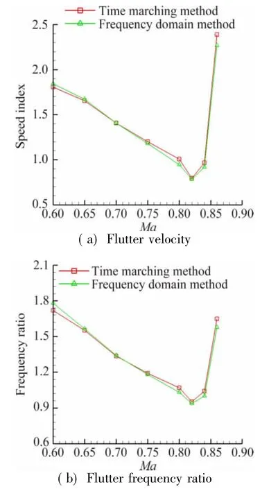
Fig.5 Comparison of viscous flutter boundaries between time-marching and frequency domain methods图5时间推进方法和频域法得到的粘性颤振边界对比

Fig.6 Inviscid damping coefficient versus speed index at Ma=0.88图6 Ma=0.88时无粘阻尼系数随来流速度的变化趋势
The inviscid and viscous flutter boundaries are shown in Figs.4 and 5.It is demonstrated that the difference between time-marching and frequency domain methods is insignificant,even in trmansonic range. The inviscid damping coefficient at Ma=0.88 is exhibited in Fig.6,from which we can obtain the reason of“S”shape flutter boundary.The damping coefficient of plunge mode exceeds zero at a low flow velocity.But as the velocity increases,the damping coefficient returns back and falls below zero at a moderate velocity.Then the damping coefficient of pitch mode exceeds zero at a high velocity.
4.3 Influence of structural parameters
If the structural parameters undergo some change,flutter boundary can be easily obtained by generalized eigenvalue analysis in frequency domain method,other than time-marching method,which must carry on numerous CFD/CSD simulations.Therefore,the influences of mass ratio and frequency ratio on viscous flutter boundary are investigated below,based on the frequency domain method.
The influences of mass ratio μ and frequency ratio ωh/ωαare shown in Fig.7 and 8 respectively.It is illustrated that higher mass ratio is preferable in subsonic region,while lower mass ratio is better in transonic region of Isogai A case.The frequency ratio also has a great impact on flutter boundary.When the frequency ratio is close to 1.0,the flutter velocity decreases significantly.
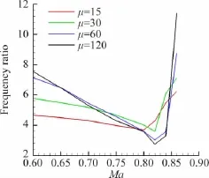
Fig.7 Influence of mass ratio on flutter velocity图7质量比对颤振速度的影响

Fig.8 Influence of frequency ratio on flutter velocity图8频率比对颤振速度的影响
5 Conclusion
1)Comparing with time-marching method,harmonic balance method is an efficient approach of periodic unsteady flow;
2)A frequency domain flutter analysis method based on harmonic balance is proposed,which shows high efficiency and precision;
3)When the structural parameters undergo some change,new flutter boundary can be obtained quickly by generalized eigenvalue analysis in the proposed frequency domain method,other than time-marching method,which must carry on a series of CFD/CSD coupled simulations.
[1]Schuster D M,Liu D D,Huttsell L J.Computational aeroelastic: success,progress,challenge[J].Journal of Aircraft,2003,40 (5):843-856.
[2]Zhang Weiwei,Ye Zhengyin.Effect of control surface on airfoil flutter in transonic flow[J].Acta Astronautica,2010,66:999-1007.
[3]Silva W A.Simultaneous excitation of multiple-input multipleoutput CFD-based unsteady aerodynamic systems[C]//48th AIAA/ ASME/AS-CE/AHS/ASC Structures,Structural Dynamics,and Materials Conference.Honolulu,Hawaii.AIAA 2007-1988.
[4]Raveh D E.Reduced-order models for nonlinear unsteady aerodynamics[J].AIAA Journal,2001,39(8):1417-1429.
[5]Zhang Weiwei,Wang Bobin,Ye Zhengyin,et al.Efficient method for limit cycle flutter analysis by nonlinear aerodynamic reducedorder models[J].AIAA Journal,2012,50(5):1019-1028.
[6]Ueda T,Dowell E H.Flutter analysis using nonlinear aerodynamic forces[C]//Proceedings of the 23rd AIAA/ASME/ASCE/AHS Structures,Structural,Dynamics,and Materials Conference,New Orleans,LA.AIAA 82-0728-CP.
[7]He S,Yang Z,Gu Y.Transonic limit cycle oscillation analysis using aerodynamic describing functions and superposition principle[J].AIAA Journal,2014,52(7):1393-1403.
[8]Woodgate M A,Badcock K J.Implicit harmonic balance solver for transonic flow with forced motions[J].AIAA Journal,2009,47 (4):893-901.
[9]Im D,Kwon J,Park S.Periodic unsteady flow analysis using a diagonally implicit harmonic balance method[J].AIAA Journal,2012,50(3):741-745.
[10]Blanc F,Roux F X,Jouhaud J C.Harmonic-balance-based codecoupling algorithm for aeroelastic systems subjected to forced excitation[J].AIAA Journal,2010,48(11):2472-2481.
[11]Hall K C,Thomas J P,Clark W S.Computation of unsteady nonlinear flows in cascades using a harmonic balance technique[J].AIAA Journal,2002,40(5):879-886.
[12]Weiss J M,Subramanian V,Hall K C.Simulation of unsteady turbomachinery flows using an implicitly coupled nonlinear harmonic balance method[C]//Proceedings of ASME Turbo Expo 2011.Vancouver,British Columbia.GT 2011-46367.
[13]Ekici K,Hall K C,Dowell E H.Computationally fast harmonic balance methods for unsteady aerodynamic predictions of helicopter rotors[C]//46th AIAA Aerospace Sciences Meeting and Exhibit.Reno,Nevada.AIAA 2008-1439.
[14]Xu Jianhua,Song Wenping,Wang Long.Application of harmonic balance method in forward flight simulation for helicopter rotors[J].Acta Aerodynamica Sinica,2013,31(5):546-553.(In Chinese)许建华,宋文萍,王龙.谐波平衡法在旋翼前飞绕流数值模拟中的应用研究[J].空气动力学学报,2013,31(5):546-553.
[15]Ronch A D,McCracken A J,Badcock K J.Linear frequency domain and harmonic balance predictions of dynamic derivatives[J].Journal of Aircraft,2013,50(3):694-707.
[16]Liu L,Thomas J P,Dowell E H,et al.A comparison of classical and high dimensional harmonic balance approaches for a Duffing oscillator[J].Journal of Computational Physics,2006,215:298-320.
[17]Davis S S.NACA64A010(NASA AMES model)oscillatory pitching[R].AGARD Report No.702.
[18]Isogai K.On the transonic-dip mechanism of flutter of a sweptback wing[J].AIAA Journal,1979,17(7):793-795.
[19]Alonso J J,Jameson A.Fully-implicit time-marching aeroelastic solutions[C]//32nd Aerospace Sciences Meeting&Exhibit.Reno,NV.AIAA-94-0056.
V211.3
A
0258-1825(2016)05-0631-07
基于谐波平衡法和V-g法的高效颤振预测分析
刘南1,白俊强1,*,刘艳1,华俊2
(1.西北工业大学航空学院,陕西西安710072;2.中国航空研究院,北京100012)
提出了一种高效的颤振预测分析方法,将之应用于跨声速颤振边界分析及结构参数影响研究中。本方法基于频域颤振分析V-g方法,为气弹系统提供一定的人工阻尼使之保持简谐运动状态,从而将结构动力学方程转换到频域内。然后通过高效的谐波平衡法得到一系列简谐运动频率下的气动力描述函数矩阵,结合频域结构方程,将气弹系统的稳定性问题转化为广义特征值求解。结果表明:本方法计算得到的颤振边界与高精度的时间推进方法非常吻合,分析效率有了明显的提升,而且当结构参数发生变化后,只需进行若干次广义特征值求解即可得到新的颤振边界,无需像时间推进方法一样开展大量的气动/结构耦合数值模拟。
颤振;频域;谐波平衡;气动力描述函数;时间推进方法
2015-09-13;
2015-11-10
刘南(1989-),男,硕士,主要研究方向:飞行器气动设计,气动弹性.E-mail:revolution890926@163.com
白俊强*(1971-),教授,博士生导师.E-mail:junqiang@nwpu.edu.cn
刘南,白俊强,刘艳,等.基于谐波平衡法和V-g法的高效颤振预测分析(英文)[J].空气动力学学报,2016,34(5):631-637.
10.7638/kqdlxxb-2015.0178 Liu N,Bai J Q,Liu Y,et al.Efficient flutter prediction based on Harmonic Balance and V-g methods[J].Acta Aerodynamica Sinica,2016,31(5):631-637.
10.7638/kqdlxxb-2015.0178
猜你喜欢
天然气与石油(2022年4期)2022-09-21
成都信息工程大学学报(2021年1期)2021-07-22
北京航空航天大学学报(2021年6期)2021-07-20
雷达学报(2018年3期)2018-07-18
电子技术与软件工程(2018年10期)2018-07-16
劳动保护(2018年5期)2018-06-05
速读·中旬(2018年4期)2018-04-28
北京航空航天大学学报(2017年3期)2017-11-23
无人机(2017年10期)2017-07-06
读写算·教研版(2016年10期)2016-06-08
