
Gas Film Disturbance Characteristics Analysis of High-Speedand High-Pressure Dry Gas Seal
2016-12-09 06:12CHENYuanJIANGJinboandPENGXudong
CHEN Yuan, JIANG Jinbo, and PENG Xudong
Gas Film Disturbance Characteristics Analysis of High-Speedand High-Pressure Dry Gas Seal
CHEN Yuan, JIANG Jinbo, and PENG Xudong*
The dry gas seal(DGS) has been widely used in high parameters centrifugal compressor, but the intense vibrations of shafting, especially in high-speed condition, usually result in DGS’s failure. So the DGS’s ability of resisting outside interference has become a determining factor of the further development of centrifugal compressor. However, the systematic researches of which about gas film disturbance characteristics of high parameters DGS are very little. In order to study gas film disturbance characteristics of high-speed and high-pressure spiral groove dry gas seal(S-DGS) with a flexibly mounted stator, rotor axial runout and misalignment are taken into consideration, and the finite difference method and analytical method are used to analyze the influence of gas film thickness disturbance on sealing performance parameters, what’s more, the effects of many key factors on gas film thickness disturbance aresystematically investigated. The results show that, when sealed pressure is 10.1MPa and seal face average linear velocity is 107.3 m/s, gas film thickness disturbance has a significant effect on leakage rate, but has relatively litter effect on open force; Excessively large excitation amplitude or excessively high excitation frequency can lead to severe gas film thickness disturbance; And it is beneficial to assure a smaller gas film thickness disturbance when the stator material density is between 3.1 g/cm3to 8.4 g/cm3; Ensuring sealing performance while minimizing support axial stiffness and support axial damping can help to improve dynamic tracking property of dry gas seal. The proposed research provides the instruction to optimize dynamic tracking property of the DGS.
high-speed and high-pressure; dry gas seal; gas film thickness disturbance; dynamic tracking property
1 Introduction
With the rapid development of modern industry, mechanical seals are more and more widely used at the operational conditions of high-speed, high-pressure and high-temperature[1]. At the same time, because of the superior sealing performances, such as zero wear, low power consumption, long life, and high stability of DGS[2], other forms of seals have been gradually replaced by DGS which is becoming the mainstream of high parameters centrifugal compressor which used in petrochemical, metallurgical and other industries. But the DGS’s balance and stability are often damaged during its running process because of the influence of many factors such as external excitation and installation deviation. So in order to ensure the DGS’s running stability and reliability at the extreme conditions, it is necessary for us to take a good knowledge of its dynamics rules.
Because of the nonlinear nature of the gas fluid film, some scholars research the DGS dynamic behavior by using direct numerical simulation method[3], this method can obtain the most reliable calculation results, but its computations are generally very time consuming and it is not conducive to an extensive parameter study[4]. Several linear analytical methods are usually used in the research of DGS dynamics, such as perturbation method, step jump method, and direct numerical frequency response method. Now the perturbation method is widely used in dynamics research by scholars like MALANOSKI, et al[5], PENG, et al[6],ZIRKELBACK, et al[7]and so on[8–10], and it is proved that the perturbation method can effectively predict the DGS dynamic behavior and obtain reliable calculation results. In this paper, the gas film dynamic characteristic coefficients, which used to solve motion equations, are calculated by the perturbation method.
A lot of research work of which about DGS dynamic tracking have been done. GREEN, et al[11], detailed the transient responses of flexibly mounted stator by solving the gas film lubrication and dynamics equations simultaneously. LIU, et al[12], proposed the occurring mechanism of angular wobble self-excited vibration of DGS, and then XU, et al[13], gave a mechanical analysis to explain the phenomenon of DGS’s angular wobble self-excited vibration. LEE, et al[14], considered the influence of external shock interferences when the possibility of face contact, the detectable central clearance between stator and rotor, and the leakage under unsteady operation were studied. There are many others related research achievements[15–22], but little of them at extreme operating conditions. Considering the need of development of DGS, this paper first research the influence of gas film thickness disturbance on sealing performance, what’s more, the effects of some key factors on gas film thickness disturbance are systematically investigated at the operational conditions of high-speed and high-pressure, and it would provide a theoretical guide for understanding DGS’s working rules and advancing DGS’s design method.
2 Models
2.1 Physical models
Fig. 1 shows a schematic cross section of a S-DGS with a flexibly mounted stator, and this model refers to Ref. [8] which published in 2002, it considers axial vibration of shaft and installation deviation of rotor. when the shaft spins, the installation deviation of rotor will provide an angular excitation motion to stator.
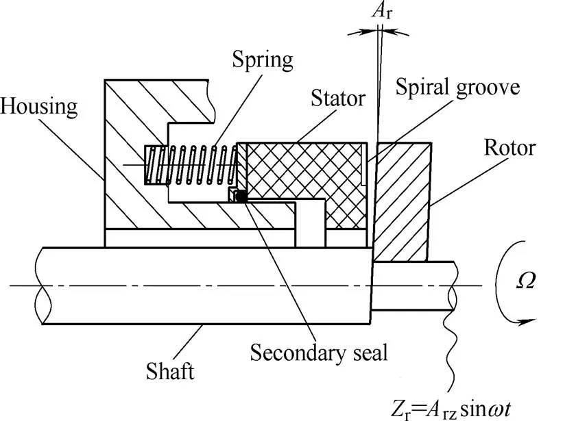
Fig. 1. Schematic cross sectionof a S-DGS
The spiral groove geometry is shown in Fig. 2(a), when the rotor revolves at a high speed, there is a large hydrodynamic pressure will be generated by the spiral grooves, which will help to separate the two seal faces and maintain a steady gas film thickness. But in most of the practical seals, the gas film thickness has a disturbance because of the rotor’s axial runout and misalignment.
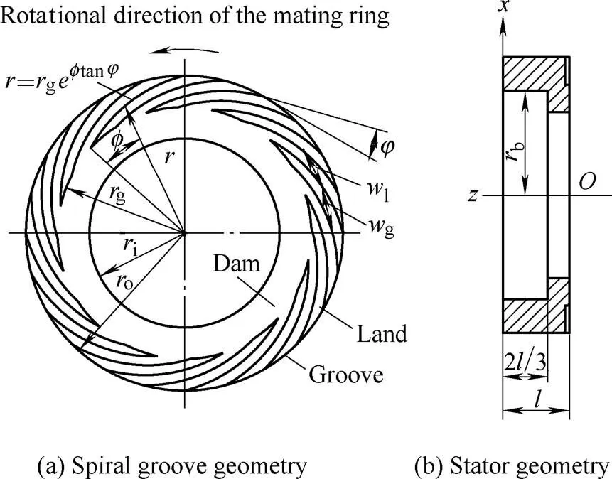
Fig. 2. Structure of the flexibly mounted ring
Fig. 3(a) shows the relative position between stator and rotor, Fig. 3(b) shows the model of seal face kinematics, and in the seal dynamic tracking property analysis, the gas film, which have a certain stiffness and damping properties, is usually treated as a spring and damper system, and the stator can be thought of as being supported by it[3]. Stator tracks rotor’s excitation motions under the function of spring, o-ring and gas film, and a good dynamic tracking property can help the seal to continuously operate with no face contact or no excessive leakage.

Fig. 3. Model of gas film thickness disturbance analysis
2.2 Mathematical models
Assuming the ideal gas and isothermal conditions, and without considering the impact of seal faces deformation in high-pressure. The transient-state compressible Reynolds equation, which governing the pressure distribution of the gas film, expressedin the polar coordinates is given by
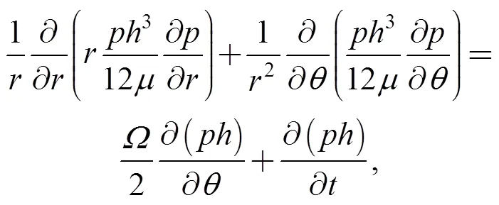
whereis transient-state pressure distribution,is transient-state gas film thickness distribution in seal face,is time; the steady-state compressible Reynolds equation expressed in the polar coordinates is given by
(2)
the perturbation compressible Reynolds equations are obtained based on Eqs. (1) and (2) by using perturbation method(the theoretical derivation refers to Ref. [8]). To introduce dimensionless variable as follows:
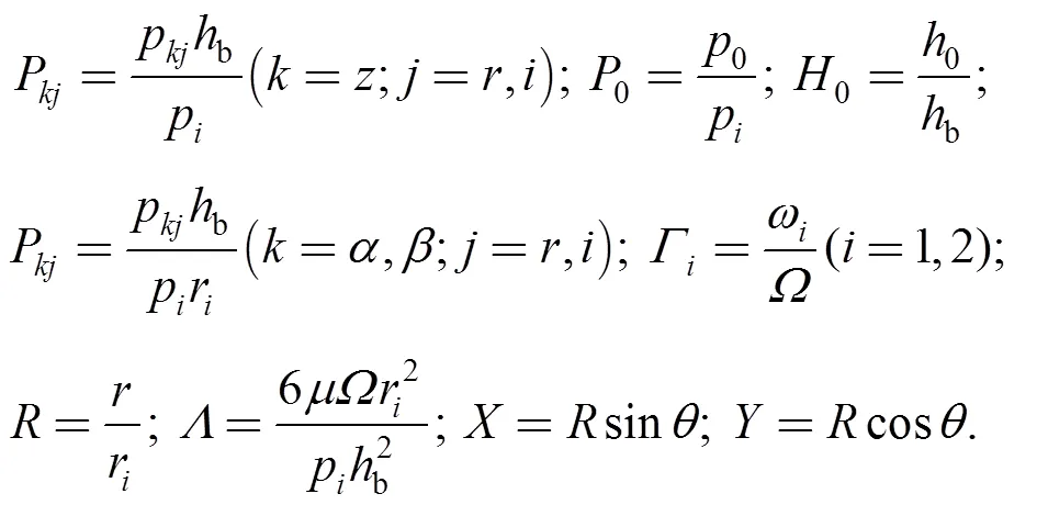
Where0is steady-state pressure distribution;z,α,βare, respectively, perturbation pressure distribution aboutaxis,axis andaxis;pis pressure at inner radius of seal ring;bis equilibrium film thickness in non-groove;0is equilibrium film thickness distribution in seal face;is the gas’s dynamic viscosity;is angular velocity of shaft;1and2are, respectively, axial and angular excitation motion angular frequency;ris stator inner radius. The expressions of dimensionless steady-state compressible Reynolds equation and dimensionless perturbation compressible Reynolds equations are shown in Eqs. (3) and (4a)–(4f):
(3)
(4b)
(4c)
The pressure boundary conditions are specified at the outer and inner radius:
And the pressure periodic boundary conditions are specified as
Combining and solving Eqs. (3) and (4a)–(4c) to obtain dimensionless perturbation gas film pressure distribution, and according to Eq. (5) to obtain dimensionless gas film dynamic coefficients:
And the dimensional gas film dynamic coefficients are
(6)
wherekandc(,=,) are gas film dynamic stiffness coefficients and damping coefficients respectively. Under the influence of support spring and secondary seal and gas film, stator will track the rotor’s motions which consist of the axial pulsation and angular wobbling. The equations of motion for both the axial mode and angular modes are expressed as follows:

(8)
(9)
In Eqs. (7)–(9),and,are, respectively, stator’s axial response motion and angular response motion;randr,rare, respectively, rotor’s axial excitation motion and angular excitation motion;is the mass of the stator;IandIare, respectively, the stator’s transverse moment of inertia aboutaxis andaxis;sis the axial stiffness of the spring,sis the axial damping of the secondary seal;sxandsyare, respectively, the angular stiffness of spring aboutaxis andaxis;sxandsyare, respectively, the angular damping of secondary seal aboutaxis andaxis.

s1ands2are, respectively, the radial position of spring and secondary seal; ands1=0.5(o+b),s2=b,ois stator outer radius,bis stator balance radius. The following excitation motions are assumed for the rotor:
(10)
The initial conditions for the stator are

It is easy and inerrable to solve Eq. (7) by using analytical method as the Eq. (7) is the linear homogeneous second-order differential equation with constant coefficients, but Eqs. (8) and (9) are coupled equations which solved much easier by using finite difference method. The seal face gas film thickness disturbance distribution Δat any time will be obtained by Eqs. (11) and (12) after the motion equations have been solved:
(11)

The transient-state gas film thickness distributionin seal face and pressure distributionare expressed as follows:
(13)
can be calculated by substituting theinto the expression of Eq. (1). Steady-state open force0and transient-state open forcearecalculated from the obtained0orby
(15)
where Δis a variation ofcaused by gas film thickness disturbance. Steady-state volume leakage rate0and transient-state volume leakage rateat inner radius pressureiarecalculated by
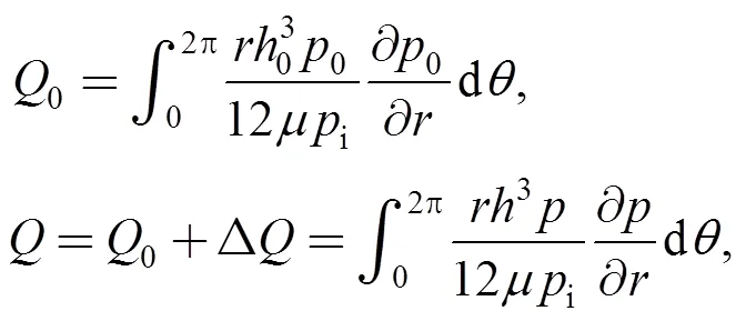
where Δis a variation ofcaused by gas film thickness disturbance. The disturbance ratesof gas film thickness distribution, open forceand volume leakage rateat any given time are defined by the expressions as following:
(17)
3 Results and Discussion
The basic calculation parameters are given in Table 1, and the choice of stator’s seal face geometry and structure parameters refers to Ref. [23]. Generally, it prescribes that the sealing medium pressure of high pressure DGS is between 3MPa and 15MPa, and the mean linear velocity of seal face of high speed DGS is between 25 m/s and 100 m/s. So this paper assigns 10.1 MPa tooand assigns 700 towhich is the equal of assigning 107.3 m/s to the mean linear velocity of seal face that is very proper to represent an operational conditions of high-speed and high-pressure. And the selection of other basic calculation parameters meets the engineering practice.The parameters will remain unchanged during the following analysis unless otherwise stated.
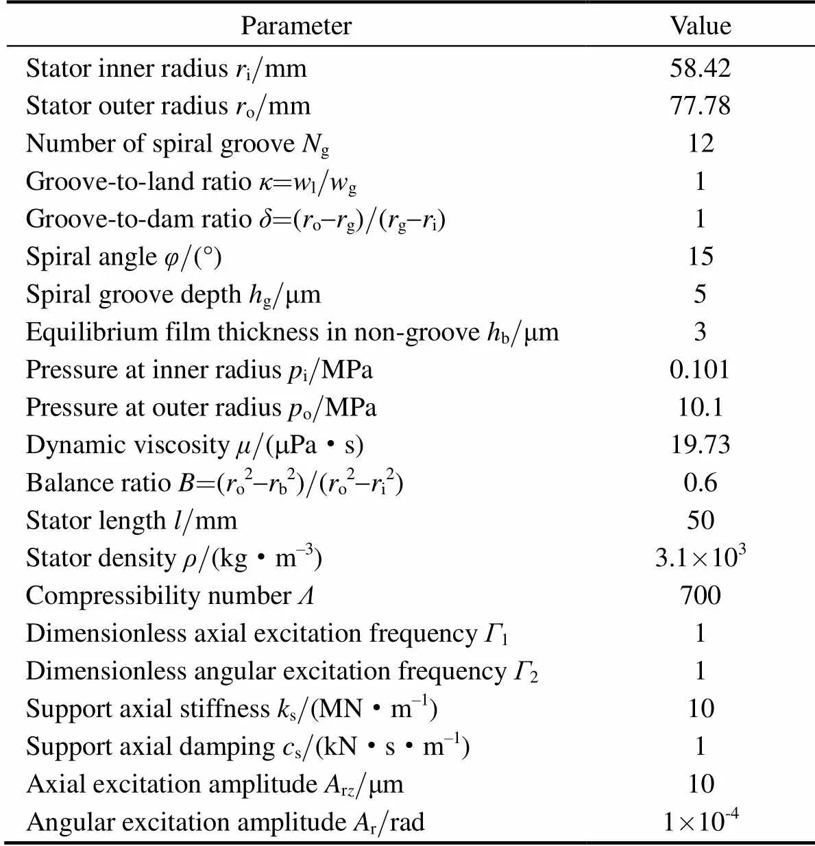
Table 1. Parameters for dynamic analysis of the S-DGS
3.1 Gas film thickness and pressure disturbance transient distribution
Fig. 4 and Fig. 5 present, respectively, the gas film thickness disturbance distributions and gas film pressure disturbance distributions at four different moments during the cycle+1, where cycle timeis period of rotation of shaft. From the Fig. 4, the positive values represent increment of gas film thickness and the negative values represent decrement of gas film thickness, and there is a maximum gas film disturbance |Δ(,)|maxon seal face at every moment. Fig. 4 shows that |Δ(,)|maxchanges with time, and too much increment or decrement of gas film thickness all will lead to too much |Δ(,)|max, this is not benefit to stable operation of S-DGS, and serious it will lead to ultimately premature seal failure because of excessive leakage or face wear, so the |Δ(,)|maxis an important parameter to represent whether S-DGS will work effectively.
The presence of gas film thickness disturbance will cause the disturbance of gas film pressure. A comparative analysis of Fig. 4 and Fig. 5 indicates that the more decrease of film thickness will lead to the more increase of film pressure, in other words, the more increase of film thickness will also lead to the more decrease of film pressure, and the Fig. 5 shows that gas film thickness disturbance have a bigger impact on film pressure disturbance in non-groove.
3.2 Influence of gas film thickness disturbance on sealing performance
Fig. 6 shows that the disturbance ratesη,ηandηchange with time, theηrepresents the biggest degree of gas film thickness change in the seal face. From the Fig. 6, it can be deduced that the Δand the opposite number of Δhave the same change rule with gas film thickness disturbance. When the maximum ofηis 3.8%, the maximum ofηandηare, respectively, 2.2% and 19.7%, so the gas film thickness disturbance have a significant effect on leakage rate, but have relatively litter effect on open force.
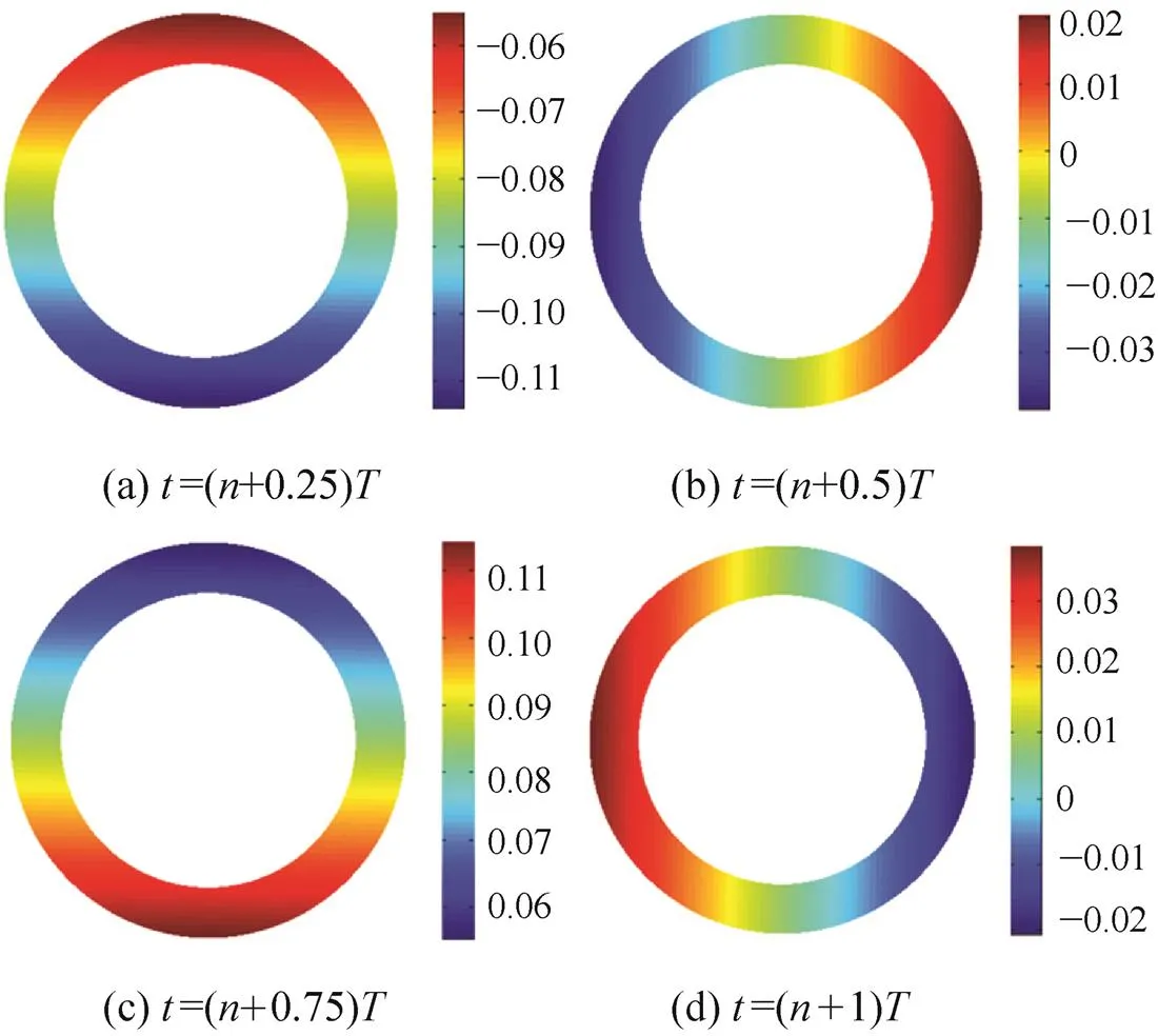
Fig. 4. Gas film thickness disturbance distribution Δ(,) (is integer,≥1,rz=50 μm)/μm
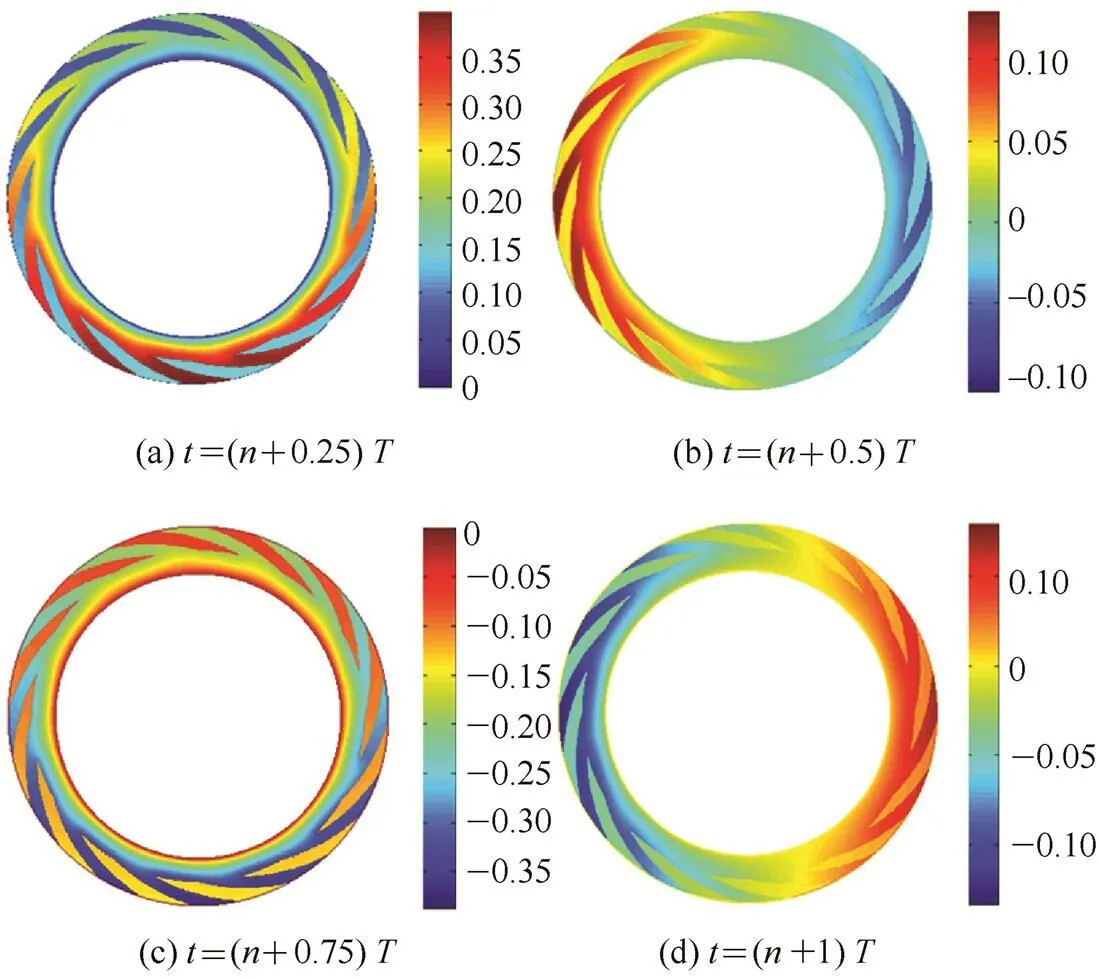
Fig. 5. Gas film pressure disturbance distribution Δ(,) (is integer,≥1,rz=50μm)/MPa
3.3 Influence of operation parameters on gas film thickness disturbance
Δ()max
Fig. 7 shows that the |Δ(,)|maxchanges with time under the different axial excitation amplitudesrz. From the Fig. 7 it can be seen that the |Δ(,)|maxfirst changes sharply in a very short time and then the change of |Δ(,)|maxgradually becomes slowly, at last, the |Δ(,)|maxpresents a cyclical change rule. We defined the cyclical change period of |Δ(,)|maxas stable phase and defined the period before the stable phase as adaptive phase. The reason of presenting the adaptive phase is that the stator will not respond quickly under the function of inertial force when it suddenly suffers the axial excitation motion of rotor, and then gradually adapts itself to the excitation. In the stable phase, the difference between the peak and the trough of |Δ(,)|maxincreases linearly with therz, and the troughs of |Δ(,)|maxare equal under the differentrz.

Fig. 6.changes with time (rz=50μm)
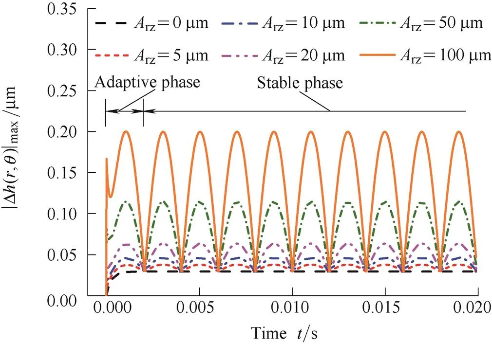
Fig. 7. |Δ(,)|maxchanges with time under the differentrz
Fig. 8 shows that the |Δ(,)|maxchanges with time under the different angular excitation amplitudesr. It is evident from Fig. 8 that the |Δ(,)|maxalso experiences the adaptive phase and the stable phase, in the stable phase, the difference between the peak and the trough of |Δ(,)|maxremains unchanged, and the troughs of |Δ(,)|maxincrease linearly with ther.
A comparative analysis of Fig. 7 and Fig. 8 indicates that, when other parameters remain the same, the troughs of |Δ(,)|maxin stable phase are all about therand the difference between the peak and the trough is all about therz. From the two figures we can conclude that the increase ofrzorraggravates the gas film thickness disturbance and deteriorates the DGS’s stability.It is hard for the DGS designers to controlrz, but easy to controlr. So in order to increase dynamic stability of DGS, designers can try to decrease installation deviation of rotor from the source, it demands that designers should not only ensure a strict geometrical tolerance range for rotor’s seal face but also for the rotor's back.
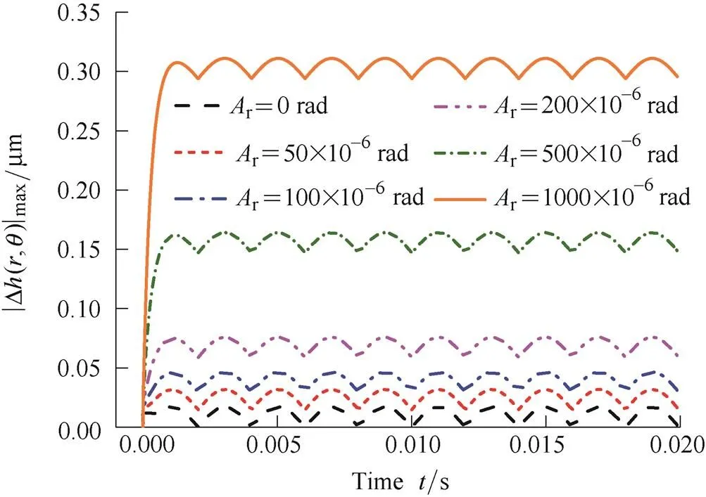
Fig. 8. |Δh(r,θ)|max changes with time under the different Ar
Δ()max
Fig. 9 illustrates the influence of dimensionless axial excitation frequency1on |Δ(,)|max. In this article, the angular excitation angular frequency2always equals angular velocityof shaft (dimensionless angular excitation frequency2=1) because the angular excitation is only caused by rotor misalignment. As shown in Fig. 9, the peak of |Δ(,)|maxincreases with the1in the adaptive phase, this is because the higher excitation frequency will lead to greater excitation displacement in a certain time, meanwhile, stator can’t track the excitation motion quickly under the function of inertial force in a very short time. Moreover, the peak of |Δ(,)|maxin adaptive phase will be greater than the peak of |Δ(,)|maxin stable phase when the1goes up to some extent, therefore, by this time the S-DGS will be more likely to happen failure of face wear or crack when it suddenly suffers the axial excitation.
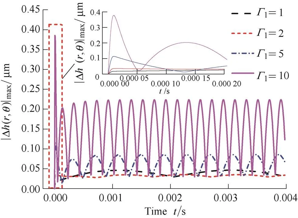
Fig. 9. |Δ(,)|maxchanges with time under the different1
In the stable phase, the peak of |Δ(,)|maxincreases and then decreases with the increase of1, this is because the increase of1can lead to the increase of axial gas film stiffness[8]which is good for DGS’s stable operation, but on the other hand, the increase of1also can intensify the gas film disturbance if the axial gas film stiffness remain unchanged. When the1increases from 1 to 2, the axial gas film stiffness plays a more important role in gas film thickness disturbance than excitation frequency, but when the1increases from 2 to 5 and to 10, the excitation frequency plays a leading role instead. It is concluded that when1is more than 2, the1is higher, the gas film thickness disturbance will become stronger, and the stability of the DGS will be worse.
3.4 Influence of structure parameters on gas film thickness disturbance
Δ()max
Fig. 10 shows that |Δ(,)|maxchanges with time under four different stator densities. It can be observed from Fig. 10 that the peak of |Δ(,)|maxincreases within the adaptive phase, this is because the inertial force increases with, and the bigger inertial force will make the stator harder respond quickly to a sudden axial excitation motion of rotor. In the stable phase, the peak of |Δ(,)|maxdecreases with the increase of, it is indicated that the inertial force is benefit to decrease the gas film thickness disturbance and improve the dynamic tracking property of stator. What’s more, it is obvious from Fig. 10 that the peak of |Δ(,)|maxin the adaptive phase will be bigger than which in the stable phase whenis big enough, thus, the seal face will be easy to be worn or be crashed when the axial excitation motion just happened. However, to choose a density of stator material which is between 3.1 g/cm3to 8.4 g/cm3can guarantee a smaller gas film thickness disturbance.
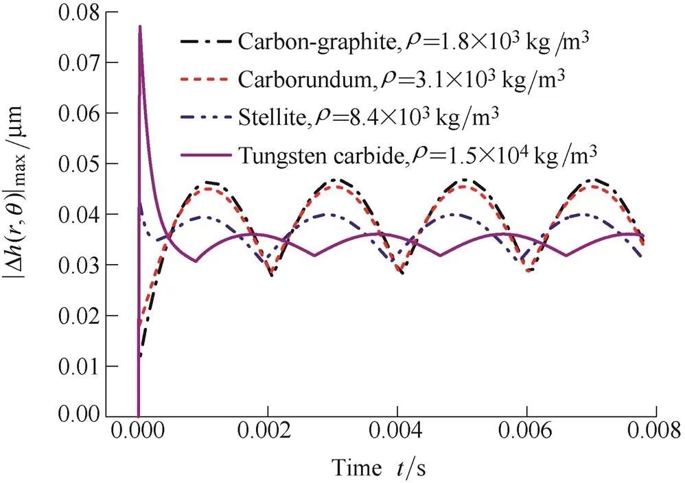
Fig. 10. |Δ(,)|maxchanges with time under the different
Δ()max
Figs. 11 and 12 show that, respectively, the |Δ(,)|maxchanges with time under the different support axial stiffnesssand dampings. From the Figs. 11 and 12 we can see that the peak of |Δ(,)|maxincreases withsors, this means that thesorsis bigger, the dynamic tracking property of stator will be worse, and the probability of DGS failure also will be greater.
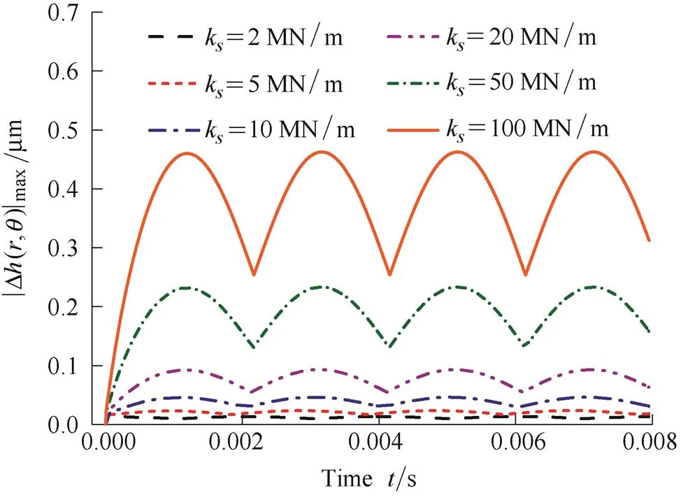
Fig. 11. |Δ(,)|maxchanges with time under the differents
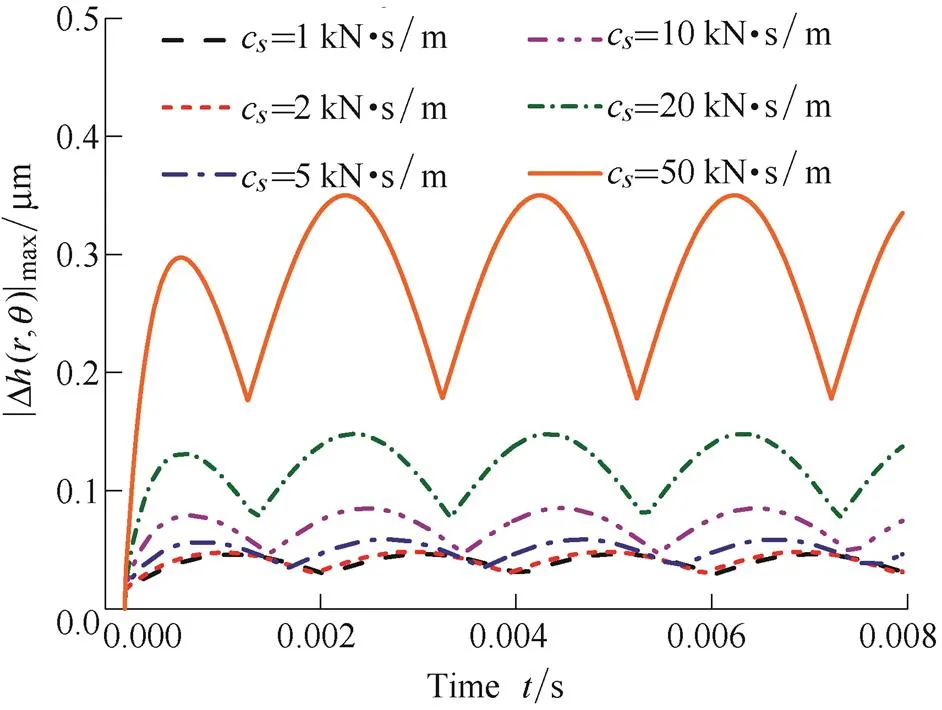
Fig. 12. |Δ(,)|maxchanges with time under the differents
When the engineers want to design a DGS with good dynamic stability, they can choose to use the springs with smaller stiffness, but they have to design a bigger spring compression to offset the close force. On the other way, designers can also use a kind of auxiliary seals material, which not only can adapt to the conditions of high-pressure and high-speed but also havea low damping, to make sure DGS run stable.
4 Conclusions
(1) The gas film thickness disturbance has a significant effect on leakage rate, but has relatively litter effect on open force.
(2) The dynamic tracking property of stator will be bad and the gas film thickness disturbance will be drastic when the excitation amplitude is very big or the excitation frequency is very high, and at this very moment the DGS is more likely to fail because of excessive leakage or face wear.
(3) No matter theis too big or too small, it will result in increase of the peak of gas film disturbance, especially when theis very big, the stator is easier to be crashed because it is hard to respond quickly to the sudden axial excitation motion, so it is better to choose a kind of stator material which theis between 3.1 g/cm3to 8.4 g/cm3; Moreover, the peak of gas film thickness disturbance almost increases linearly withsors, thus, in order to ensure a good operation stability for DGS we should try to decreasesandswhile guaranteeing sealing performance.
[1] PENG Xudong, WANG Yuming, HUANG Xing, et al. State-of- the-art and future development of sealing technology[J]., 2009(4): 4–11. (in Chinese)
[2] ZHOU Jianfeng, GU Boqin. Characteristcs of fluid film in optimized spiral groove mechanical seal[J]., 2007, 20(6): 54–61.
[3] GREEN I, BAMSBY R M. A parametric analysis of the transient forced response of noncontacting coned-face gas seals[J]., 2002, 124(1): 151–157.
[4] LIU Xiangfeng, XU Chen, HUANG Weifeng. Analysis and parametric design of the dynamics of a dry gas seal for extreme operating conditions using a semi-analytical method[J]., 2014(2): 223–228. (in Chinese)
[5] MALANOSKI S B, PAN C H T. The static and dynamic characteristics of the spiral-grooved thrust bearing[J]., 1965, 87(3): 547–555.
[6] PENG J P, CARPINO M. Calculation of stiffness and damping coefficients for elastically supported gas foil bearings[J]., 1993, 115(1): 20–27.
[7] ZIRKELBACK N, SAN A L. Effect of frequency excitation on force coefficients of spiral groove gas seals[J]., 1999, 121(4): 853–861.
[8] RUAN B. A semi-analytical solution to the dynamic tracking of non-contacting gas face seals[J]., 2002, 124(1): 196–202.
[9] FARIA M T C. Finite element analysis of the misalignment effects on the dynamic force coefficients of spiral groove gas face seals[J]., 2004, 47(1): 289–296.
[10] BAI Shaoxian, PENG Xudong, MENG Xiangkai. Stability of laser textured gas-lubricated non-contact mechanical seal[J]., 2010, 30(6): 521–526. (in Chinese)
[11] GREEN I, BAMSBY R M. A simultaneous numerical solution for the lubrication and dynamic stability of noncontacting gas face seals[J]., 2001, 123(2): 388–394.
[12] LIU Yuchuan, XU Wangfu, WANG Zhili, et al. Stability of angular wobble self-excited vibrations for gas film face seal[J]., 2002, 38(4): 1–6. (in Chinese)
[13] XU Wangfu, LIU Yuchuan, WANG Zhili, et al. Reason of angular wobble self-excited vibration and half frequency characteristic for gas film face seal[J]., 2002, 38(9): 43–46. (in Chinese)
[14] LEE S C, ZHENG X L. Analyses of both steady behavior and dynamic tracking of non-contacting spiral-grooved gas face seals[J]., 2013, 88: 326–333.
[15] MILLER B A, GREEN I. Numerical formulation for the dynamic analysis of spiral-grooved gas face seals[J]., 2001, 123(2): 395–403.
[16] MILLER B A, GREEN I. Numerical techniques for computing rotordynamic properties of mechanical gas face seals[J]., 2002, 124(4): 755–761.
[17] RUAN B. Numerical modeling of dynamic sealing behaviors of spiral groove gas face seals[J]., 2002, 124(1): 186–195.
[18] MILLER B A, GREEN I. Semi-analytical dynamic analysis of spiral-grooved mechanical gas face seals[J]., 2003, 125(2): 403–413.
[19] YELMA S S, MILLER B A, LANDERS R G. Clearance regulation of mechanical gas face seals: part I—modeling[J]., 2006, 49(3): 361–372.
[20] ZHANG H, MILLER B A, LANDERS R G. Nonlinear modeling of mechanical gas face seal systems using proper orthogonal decomposition[J]., 2006, 128(4): 817–827.
[21] ZHANG H, LANDERS R G, MILLER B A. Adaptive control of mechanical gas face seals with rotor runout and static stator misalignment[J]., 2010, 132(4): 041009.
[22] BLASIAK S, ZAHORULKO A V. A parametric and dynamic analysis of non-contacting gas face seals with modified surfaces[J]., 2016, 94: 126–137.
[23] PENG Xudong, JIANG Jinbo, BAI Shaoxian, et al. Correlational research of bionics design of dry gas face seal groove[J]., 2014, 50(3): 151–157. (in Chinese)
Biographical notes
CHEN Yuan, born in 1990, is currently a PhD candidate at. His research interest is the modern fluid sealing technology.
E-mail: chenyuan_1221@163.com
JIANG Jinbo, born in 1989, is currently a PhD candidate at. His research interest is the modern fluid sealing technology.
E-mail:jinbo_110@163.com
PENG Xudong, born in 1964, is currently a professor at. His research interests include the modern fluid sealing technology and tribological design of mechanical equipment.
Tel: +86-571-88320212; E-mail:xdpeng@zjut.edu.cn
Received December 9, 2015; revised May 9, 2016; accepted June 17, 2016
Supported by National Natural Science Foundation of China(Grant No. 51575490), National Key Basic Research Program of China(973 Program, Grant No. 2014CB046404), and Natural Science Key Foundation of Zhejiang Province, China (Grant No. LZ15E050002)
© Chinese Mechanical Engineering Society and Springer-Verlag Berlin Heidelberg 2016
10.3901/CJME.2016.0617.074, available online at www.springerlink.com; www.cjmenet.com
E-mail: xdpeng@zjut.edu.cn
 Chinese Journal of Mechanical Engineering2016年6期
- Chinese Journal of Mechanical Engineering的其它文章
- Surface Topography and Roughness of High-speed Milled AlMn1Cu
- Integrated Simulation Method for Interaction between Manufacturing Process and Machine Tool
- Engineering the Smart Factory
- Exploring Barriers and Opportunities in Adopting Crowdsourcing Based New Product Development in Manufacturing SMEs
- Development of the Supply Chain Oriented Quality Assurance System for Aerospace Manufacturing SMEs and Its Implementation Perspectives
- Collaborative Simulation Method with Spatiotemporal Synchronization Process Control