
基于自相似模型的气井管柱中流体的近壁压力试验研究
2017-06-27 08:13刘铭刚闫怡飞王建军韩生超杨秀娟闫相祯
中国石油大学学报(自然科学版) 2017年2期
刘铭刚, 闫怡飞, 谢 巍, 王建军, 韩生超, 杨秀娟, 闫相祯
(1.中国石油大学储运与建筑工程学院,山东青岛 266580; 2.中国石油大学油气CAE技术研究中心,山东青岛 266580;3.中国石油大学机电工程学院,山东青岛 266580; 4.华北油田采油工程研究院,河北任丘 062552;5.中国石油集团石油管工程技术研究院,陕西西安 710077)
基于自相似模型的气井管柱中流体的近壁压力试验研究
刘铭刚1,2, 闫怡飞2,3, 谢 巍4, 王建军5, 韩生超1,2, 杨秀娟1,2, 闫相祯1,2
(1.中国石油大学储运与建筑工程学院,山东青岛 266580; 2.中国石油大学油气CAE技术研究中心,山东青岛 266580;3.中国石油大学机电工程学院,山东青岛 266580; 4.华北油田采油工程研究院,河北任丘 062552;5.中国石油集团石油管工程技术研究院,陕西西安 710077)
气井管柱内流体运动状态和近壁压力分布的确定对井筒安全和完整性评价有重要意义。从相似性原理出发设计气井管柱流体力学试验,通过尺寸比尺和流速控制实现模型与原型的几何相似和雷诺数自相似,采用试验和数值计算对气井造斜弯曲段管柱近壁压力进行对比研究,利用相对误差分析验证试验的可行性。结果表明:气井管柱室内流体试验满足雷诺数自相似下的几何相似条件;当取运动黏度为试验不变量时,管柱近壁压力的试验模拟结果与数值计算结果相比偏小,当试验压差为0~20 MPa时,近壁压力最大相对误差为4.12%,且压差越大,相对误差越小;随着生产压差(pp=5~20 MPa)和油管内径(D=76.00~157.08 mm)的增大,管柱整体近壁压力和沿程压力降增大;造斜弯曲段流入端的局部压程比随油管内径增大而增大,流出端规律相反。满足几何相似和雷诺自相似条件的管柱流体试验是气井管柱近壁压力研究的有效手段。
管柱; 流体试验; 近壁压力; 相似理论; 储气库
现阶段对气井管柱内流体运动状态和沿程近壁压力的研究方法主要为试验井检测和数值计算。试验井设计施工难度高、成本巨大,且可模拟工况单一,难以作为技术创新和科学研究的有效手段;数值计算方法模型成熟、工况设计简单,且结果提取和分析相对简单,是目前广大学者和科研机构在油气井井筒流体状态研究方面的主要研究手段,然而运存资源占用大、网格质量要求高、计算效率低等缺点使其很难用于大井深或完整管柱段内的流体状态建模和计算[1-10]。有学者拟设计类似低流速输运管道小尺寸流体力学试验的气井管柱室内试验,对天然气在注采过程中的状态进行研究,但都受制于无法完全满足相似性试验设计原理中的流体动力学相似而止步。目前国内外学者对室内小尺寸流体试验及相应数值试验的设计主要是针对低流速管流开展的,如Stack、Zhang等[11-16]对管道的弯管段流体冲蚀问题开展了研究,Elling等[17]设计了气体在粗糙管路中的流动状态对比试验,研究了管壁摩阻对管路沿程压力分布的影响规律,Ferng等[18-19]对输气薄壁管道的冲蚀问题进行数值模拟,Mazumder等[20-22]为确定管道冲蚀位置进行了试验研究;Kays等[23-26]对流体流经变径管路和突变截面时的运动状态进行了理论和数值计算。在气井管柱方面,比较代表性的有Savidge等[27]推导了理想气体音速流动时的运动状态方程并与低速流进行比较,Zhu等[28-30]利用计算流体力学(CFD)方法对气体钻井中冲蚀问题进行了探索,练章华、王嘉淮等[31-32]分别对高压气井和地下储气库井管柱气体冲蚀问题进行了初步研究,但都由于缺少参考试验无法对理论计算结果进行验证。针对这些研究现状,笔者设计满足几何相似和雷诺自相似条件的气井管柱流体试验,测量管柱沿程近壁压力,研究注采压差和油管内径对管柱沿程近壁压力的影响规律,并与数值计算结果对比,通过相对误差分析验证试验方案的可行性。
1 物理试验
1.1 相似性原理和模型参数
地下储气库井注入工况下,天然气经压缩机压缩后注入井底,采出工况时天然气自井底流向带压井口,可认为天然气在油管柱内以压缩状态做单相运动。要使试验模型(用下标m表示)与原型(用下标p表示)具有相同的流动规律,利用模型预测原型流场状态,模型与原型须满足流动相似条件,即两个流动在对应时刻对应点上同名物理量具有各自的比例关系。具体地,流动相似就是要求模型与原型之间满足几何相似、运动相似和黏度相似条件。考虑采气工况下天然气在管柱内的流动为可压缩的等熵流动(天然气等熵指数n=1.27~1.30),有
p/ρn=K.
(1)
式中,K为常数。
定义雷诺数Re为决定性相似准数,则根据雷诺数相等得到相似条件:
Re=ρpUpLp/μp=ρmUmLm/μm.
(2)
根据流动相似准则,模型与原型的比尺须满足的关系为
λU=λν/λL.
(3)
其中

式中,p为天然气压力,Pa;ρ为天然气密度,kg·m-3;L为管路长度,m;D为管路内径,m;λL、λU和λν分别为几何比尺、速度比尺和黏度比尺。
表1为试验管路规格与实际油管规格对照。由表1可以得到原型与模型的几何比尺(以管柱规格Φ114.3 mm×7.37 mm为例,下同)为
λL=Lp/Lm=1200.0/40.0=28,
(4)
λL=Dp/Dm=99.56/3.556=28.
(5)
天然气与试验气体(空气)物理参数对照如表2所示。试验中忽略两种气体黏度差异性,则原型与模型的黏度比尺满足
λν=νp/νm=1.
(6)
由式(3)可知满足流动相似条件下的原型与模型的速度比尺为
λU=1/λL=28.
(7)
根据流体力学理论,当流体运动进入自模化状态时,流体紊乱程度及速度剖面几乎不再变化,称为流体的雷诺数自相似现象。由文献[34-35]可知,生产过程中的高产气井和地下储气库井管柱内天然气处于完全紊流粗糙管区,此时气体满足雷诺数自相似条件,运动相似条件被放松。试验中取模型速度参数与原型一致,即
Um=Up.
(8)
至此,满足相似条件的气井管柱流体试验模型得以建立。根据上述相似模型,当实际油管内径99.56 mm、目标井段油管长度取1 200 m时,试验模型参数为:油管内径3.556 mm,油管长度40.0 m,入口气体流速120 m·s-1,空气运动黏度15.8 mm2·s-1。
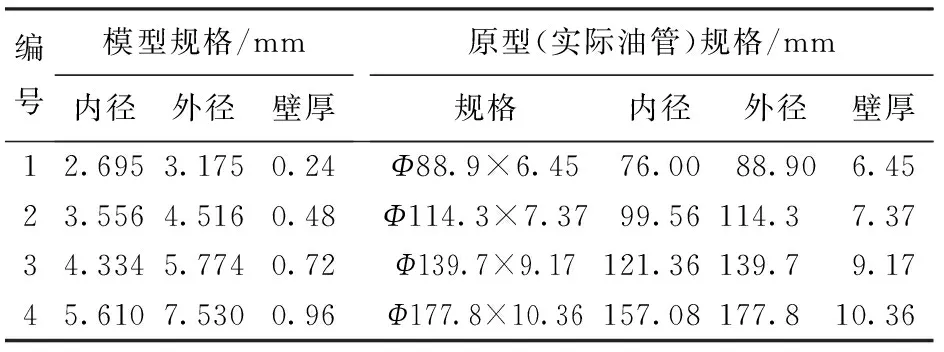
表1 试验管路规格与实际油管规格对照Table 1 Specifications comparison of test tubing and actual tubing

表2 试验气体物理参数Table 2 Physical and mechanical parameters of natural gas
1.2 试验流程设计
根据相似模型设计试验,对沿程近壁压力进行测量,试验装置和数据采集单元分别如图1、 2所示。
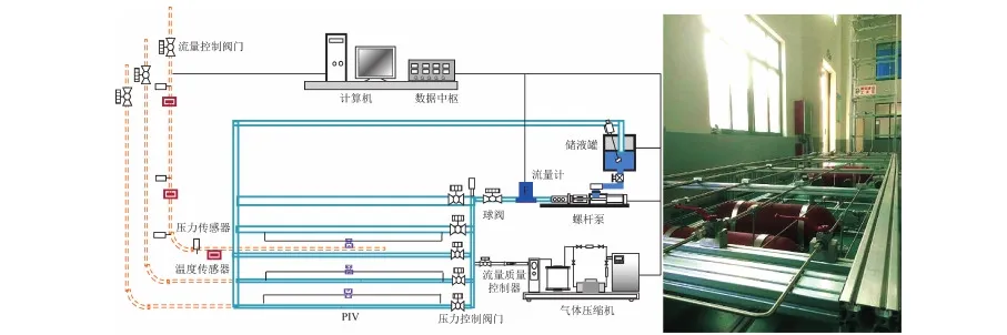
图1 试验装置结构框图和现场照片Fig.1 Diagram and picture of experimental apparatus unit structure

图2 试验数据采集单元结构Fig.2 Experimental data collection unit structure
试验管路由空压机、增压泵、气体储气罐、高压管路、压力表等构成。由空压机提供流量,用增压泵将气体增压到所需压力,储气罐稳定流量,根据试验需要设置4组不同直径的管路,用含接箍短管模拟变截面管柱段,设置切换阀门控制管路状态,注入压力和流出压力由压力传感器和差压传感器测量。
试验装置及数据采集原理及系统界面如图2所示。4路压力信号和2路流量计信号由模拟量输入模块7017采集,经7520转换成RS232协议与计算机连接。温度信号由7033采集。球阀由7024输出电压控制。应变片数据由应变仪采集。流体泵状态由变频器与计算机连接进行控制。管路内气体流速由PIV粒子图像测速仪测定并转化为数字信号进行输出。
1.3 工况设置和试验结果
以某储气库试验井S-4井身结构为基础,根据实际井身数据设计试验管路。试验井为定向井,井身参数如表3所示。
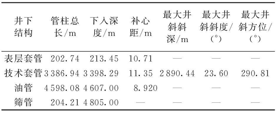
表3 试验井S-4井身参数Table 3 Well parameters of test well S-4
试验井底压力为20 MPa。设置以下试验工况:管柱规格分别取Φ88.9 mm×6.45 mm、Φ114.3 mm×7.37 mm、Φ139.7 mm×9.17 mm和Φ177.8 mm×10.36 mm,注气量分别取20×104m3·d-1(对应压差5 MPa)、30×104m3·d-1(对应压差10 MPa)、40×104m3·d-1(对应压差15 MPa)和50×104m3·d-1(对应压差20 MPa)。试验工况如表4所示。测量造斜弯曲段(对应井深1 200~2 400 m井段)油管柱近壁压力沿程分布,结果如表5所示。
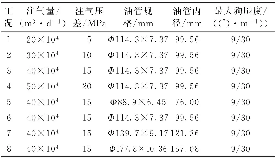
表4 试验工况设置Table 4 Test conditions
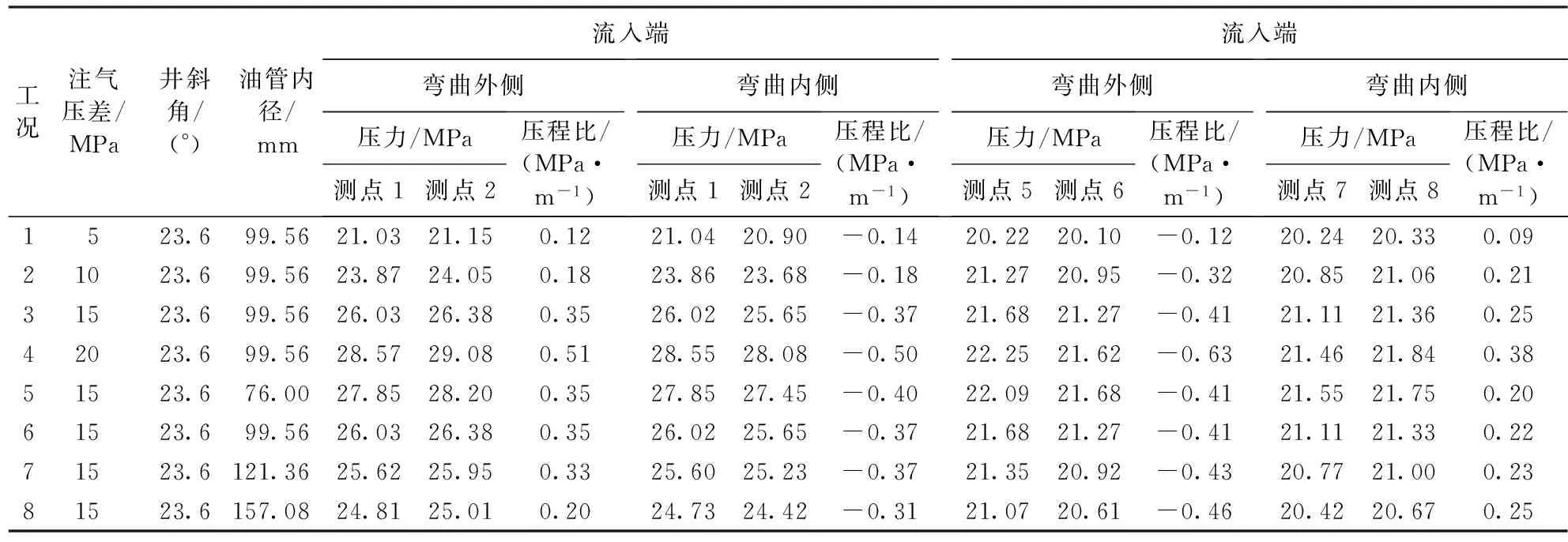
表5 造斜弯曲段油管近壁压力Table 5 Near-wall pressure of whipstocking segment
2 数值模拟
2.1 数值模型
为了对物理试验进行修正,基于ANSYS CFX/CFD模块对表4中井身参数进行数值建模和计算。基于CFX/CFD的数值计算方法作为目前高速管流研究的有效手段,其在气井管柱沿程流体压力计算的精度和可靠性已经验证[25-26]。管柱几何模型和单元划分如图3所示。模型以入口端面为源面,采用六面体网格进行单元划分,弯曲管柱段采用楔形网格过渡和加密。设置管柱流入、流出端为压力边界,压缩机出口(流入端)压力恒定,参考环境温度(56.25 ℃)。假定油管壁面无滑移,选用Segregated Solver算法求解。
2.2 模型理论
引入Renormalization-group(RNG)k-ε涡黏湍流模型[28-30],该模型的连续方程和运动方程分别为

(9)
(10)
式中,xi,j,w对应空间坐标系中的i,j,w方向;Ui,j,w为流体在i,j,w方向上的瞬时速度分量;SM为体积力;ρ为相对密度;μeff为有效动力黏度,数值上等于分子(动力)黏度μ与湍流黏度μt之和;p为静压。
对实际可压缩流体修正为

(11)
式中,p0为流体不可压缩时的静压。

图3 数值模型及网格划分Fig.3 Meshes of tubing and packer model
(12)
由传递方程[31-32]
Gw+Gb-YM-ρε,
(13)

(14)
可得到湍动能k和湍动能耗散率ε,至此方程(8)、(9)封闭。
其中
2.3 计算结果
日注气量为40×104m3,井斜角为23.6°(最大狗腿度为9°/30 m),采用Φ114.3 mm×7.37 mm油管时,试验井油管柱内天然气近壁压力的截面分布如图4所示。从图4可以看出:(1)管柱近壁压力沿程分布受井身结构影响很大。高速天然气流入造斜段时,管柱外壁压力增大,内壁压力减小;(2)天然气流出造斜段时,压力分布随狗腿度减小逐渐趋于均匀。
3 影响参数分析
3.1 注采压差
管柱规格和井身结构确定时(井斜角23.6°,油管Φ114.3 mm×7.37 mm),地下储气库井筒天然气状态受注气压差影响。图5、 6分别为地下储气库井筒底部压力恒定(20 MPa),注气压差分别为5、10、15和20 MPa时,造斜弯曲段油管柱内沿程近壁压力的物理试验和数值试验结果。
从图5可以看出,随着试验压差的增大,注气过程中沿井身整体近壁压力降Δp(管柱沿程上两点间的近壁静压之差)增大,整体压程比Ψ(管柱沿程上两点间的近壁静压之差与两点距离的绝对值之比)相应增大。从图6可以看出,试验压差从5 MPa提高到20 MPa的过程中,流入端弯曲外侧两测点的平均压降变化率为36.7%,弯曲内侧两测点的平均压降变化率为35.0%,相应局部压程比变化率为325%和257%;流出端弯曲外侧两测点的平均压降变化率为8.80%,弯曲内侧两测点的平均压降变化率为6.73%,相应局部压程比变化率为425%和322%;说明造斜弯曲段流入、流出端的局部压程比随压差增大而增大,其中弯曲外侧近壁压力相比弯曲内侧对应位置增幅更大,因此造斜弯曲段局部最大压降最有可能发生在流入端弯曲外侧或流出端弯曲内侧。
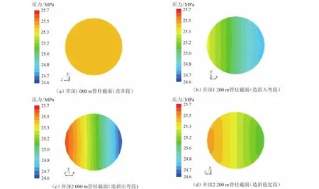
图4 油管内压力截面分布云图Fig.4 Distribution of pressure cross section in tubing

图5 造斜弯曲段油管柱内沿程近壁静压随压差变化规律Fig.5 Near wall static pressure variation with pressure in tubing of whipstocking
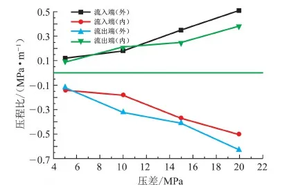
图6 造斜弯曲段流入、流出端局部压程比随压差变化规律Fig.6 Pressure-distance rate variation with pressure in tubing of whipstocking
3.2 油管内径
油管规格由内径和壁厚确定。研究井斜角和日注气量一定(井斜角为23.6°、注气量40×104m3·d-1)时地下储气库油管柱近壁压力变化规律。图7、 8分别为油管规格取Φ88.9 mm×6.45 mm、Φ114.3 mm×7.37 mm、Φ139.7 mm×9.17 mm、Φ177.8 mm×10.36 mm时,造斜弯曲段管柱沿程近壁压力物理试验和数值试验结果。
从图7可以看出,随着油管内径的增大,注气过程中沿井身整体近壁压力和压力降增大。从图8可以看出,油管内径增大时,流入端弯曲外侧两测点的平均压降变化率为-11.1%,弯曲内侧两测点的平均压降变化率为-11.0%,相应局部压程比变化率为-42.9%和-22.5%;流出端弯曲外侧两测点的平均压降变化率为-4.77%,弯曲内侧两测点的平均压降变化率为-5.10%,相应局部压程比变化率为12.2%和25.0%;说明造斜弯曲段流入端局部压程比随管径增大而减小,流出端规律相反。

图7 造斜弯曲段油管柱内沿程近壁静压随油管内径变化规律Fig.7 Near wall static pressure variation with inner diameter in tubing of whipstocking
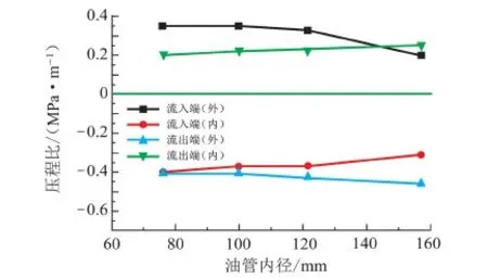
图8 造斜弯曲段流入、流出端局部压程比随油管内径变化规律Fig.8 Pressure-distance rate variation with inner diameter in tubing of whipstocking
3.3 试验结果分析
从图6、8可以看出,气井管柱内流体室内小尺寸试验的近壁压力分布及变化规律与数值试验计算结果相比数值偏小,但误差范围稳定,说明当简化流体黏度和速度比尺时,满足几何相似的小尺寸试验可以较好地描述管柱沿程近壁流体压力分布和参数变化规律。表6列出了沿井身管柱测点1、2处近壁压力的试验结果和数值结果对比,其他测点可类似处理。
从表6可以看出,对比数值结果,试验测得近壁压力最大误差为4.12%,在容许范围内。注气压差从5 MPa增大到20 MPa过程中,测点1和测点2弯曲外侧静压的试验误差从4.11%减小到2.91%,内侧静压的试验误差从4.12%减小到2.95%,说明压差增大,可以降低试验误差;从表6中还可以看出,油管内径对试验误差影响很小,可忽略。
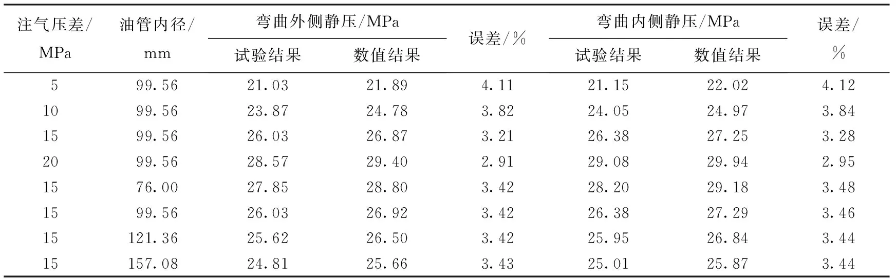
表6 管柱近壁压力的试验结果和数值结果对比Table 6 Near-wall pressure comparison of test and numerical results
4 计算实例对比分析
现场储气库S-4井油管总长为4 805 m,井身结构如表3所示。日注气量40×104m3,平均狗腿度为9°/30 m,油管规格为Φ114.3 mm×7.37 mm,初始井底流压为20 MPa,压缩机出口压力为35 MPa(恒定),气体密度为0.59 kg·m-3,动力黏度为16.07 μPa·s,运动黏度为22.07 mm2·s-1,比定压热容为2.23 kJ·kg-1·K-1,比定容热容为1.70 kJ·kg-1·K-1。当压力修正系数取1.287时,井下压力探测器反馈的油管近壁压力沿井身分布与本文中试验测得结果对比见图9。由此可以看出,本文试验结果与现场实测结果吻合度较好,说明气井管柱流体试验作为井下压力检测的辅助技术,其结果可为气井管柱设计、生产效果预估提供一定参考。

图9 油管近壁压力分布试验结果与现场测量结果对比Fig.9 Comparison of experimental results and field measurements of near-wall pressure distributions
5 结 论
(1) 气体处于完全紊流粗糙管区时满足雷诺数自相似条件,气井管柱流体试验通过尺寸比尺实现几何相似,通过流速控制实现雷诺数自相似。
(2) 近壁压力的试验结果与数值结果相比结果偏小,但相对误差在容许范围内,且随着压差增大,试验误差减小。
[1] 丁国生,李春,王皆明,等.中国地下储气库现状及技术发展方向[J].天然气工业,2015,35(11):107-112. DING Guosheng, LI Chun, WANG Jieming,et al. The status quo and technical development direction of underground gas storages in China[J]. Natural Gas Industry, 2015,35(11):107-112.
[2] 丁国生.中国地下储气库的需求与挑战[J].天然气工业,2011,31(12):90-93. DING Guosheng. Demand and challenges for underground gas storages in China [J]. Natural Gas Industry, 2011,31(12):90-93.
[3] 肖学兰.地下储气库建设技术研究现状及建议[J].天然气工业,2012,32(2):79-82. XIAO Xuelan. Research and proposals on underground gas storage construction technologies [J]. Natural Gas Industry, 2012,32(2):79-82.
[4] 袁光杰,杨长来,王斌,等.国内地下储气库钻完井技术现状分析[J].天然气工业,2013,33(2):61-64. YUAN Guangjie, YANG Changlai, WANG Bin,et al. Drilling and completion technologies for the underground gas storage (UGS) in China: a state-of-the-art appraisal [J]. Natural Gas Industry, 2013,33(2):61-64.
[5] 刘坤,何娜,张毅,等.相国寺储气库注采气井的安全风险及对策建议[J].天然气工业,2013,33(9):131-135. LIU Kun, HE Na, ZHANG Yi,et al. Safety risk analysis of gas injection and recovery wells in the Xiangguosi gas storage and countermeasures [J]. Natural Gas Industry, 2013,33(9):131-135.
[6] 练章华,韩建增,董事尔.基于数值模拟的复杂地层套管破坏机理研究[J].天然气工业,2002,22(1):48-51. LIAN Zhanghua, HAN Jianzeng, DONG Shier. Research on the casing failure mechanism of complex formation by numerical simulation [J]. Natural Gas Industry, 2002, 22(1):48-51.
[7] 林勇.储气库注采井钻完井方案设计[D].西安:西安石油大学,2013. LIN Yong. Plan design of well drilling and completion for injection and production wells of underground gas storages [D]. Xian: Xian Shiyou University, 2013.
[8] 王霞. 储气库井生产动态分析方法及应用[D]. 西安: 西安石油大学, 2015. WANG Xia. Well production dynamic analysis method and application of gas storage [D].Xian: Xian Shiyou University, 2015.
[9] PATANKAR S V. Numerical heat transfer and fluid flow [M]. Fremont:Hemisphere Publishing Corporation, 1980.
[10] WILCOX D C. Turbulence modeling for CFD [M]. La Canada: DCW Industries, 2006.
[11] STACK M M, ABDELRAHMAN S M. A CFD model of particle concentration effects on erosion-corrosion of Fe in aqueous conditions[J]. Wear, 2011,273:38-42.
[12] ZHANG H, TAN Y Q, YANG D M, et al. Numerical investigation of the location of maximum erosive wear damage in elbow: effect of slurry velocity, bend orientation and angle of elbow [J]. Powder Technology, 2012,217:467-476.
[13] TAN Y Q, ZHANG H, YANG D M,et al. Numerical simulation of concrete pumping process and investigation of wear mechanism of the piping wall [J]. Tribol Int, 2012,46:137-144.
[14] LI R, YAMAGUCHI A, NINOKATA H. Computational fluid dynamics study of liquid droplet impingement erosion in the inner wall of a bend pipe [J]. J Power Energy Syst, 2010,4:327-336.
[15] SUZUKI M, INABA K, YAMAMOTO M. Numerical simulation of sand erosion in a square-section 90-degree bend [J]. J Fluid Sci Technol, 2008,3:868-880.[16] ZENG L, ZHANG G A, GUO X P. Erosion-corrosion at different location of X65 carbon steel elbow [J]. Corros Sci, 2014,85:318-330.[17] SLETFJERDING, ELLING, GUDMUNDSSON,et al. Friction factor directly from roughness measurements [J]. Journal of Energy Resources Technology, Transactions of the ASME, 2003,125(2):126-130.
[18] FERNG Y M. Predicting local distributions of erosion—corrosion wear sites for the piping in the nuclear power plant using CFD models [J]. Ann Nucl Energy, 2008,35:304-313.
[19] FERNG Y M, LIN B H. Predicting the wall thinning engendered by erosion-corrosion using CFD methodology [J]. Nucl Eng Des, 2010,240:2836-2841.
[20] MAZUMDER Q H, SHIRAZI S A, MCLAURY B. Experimental investigation of the location of maximum erosive wear damage in elbows [J]. ASME J Press Vessel Technol, 2008,130:11303-1-8.
[21] MAZUMDER Q H, SHIRAZI S A, MCLAURY B. Prediction of solid particle erosive wear of elbows in multiphase annular flow-model development and experimental validations[J]. J Energy Resour Technol, 2008,130:023001-1-10.
[22] DENG T, PATEL M, HUTCHINGS I, et al. Effect of bend orientation on life and puncture point location due to solid particle erosion of a high concentrated flow in pneumatic conveyors [J]. Wear, 2005,258:426-433.
[23] KAYS W M. Loss coefficient for abrupt changes in flow cross section with low Reynolds flow in single and multi-tube systems [J]. Transactions of the ASME Journal of Fluids Engineering, 1950,72:1067-1074.
[24] ASTARITA G, GREGO G. Excess pressure drop in laminar flow through sudden contraction[J]. Fundamentals, 1968,7(1):27-31.[25] HABIB M A, BADR H M, MANSOUR R, et al. Numerical calculations of erosion in an abrupt pipe contraction of different contraction ratios [J]. International Journal for Numerical Methods in Fluids, 2004,46:19-35.[26] BADR H M, HABIB M A, MANSOUR R,et al. Numerical investigation of erosion threshold velocity in a pipe with sudden contraction [J]. Computers and Fluids, 2005,34:21-42.
[27] JAESCHKE M, SCHLEY P. Ideal-gas thermodynamic properties for natural-gas applications[J]. International Journal of Thermophysics, 1995,16(6):1381-1392.
[28] ZHU H J, LIN Y H, ZENG D Z,et al. Numerical analysis of flow erosion on drill pipe in gas drilling [J]. Eng Fail Anal, 2012,22:83-91.
[29] ZHU H J, WANG J, CHEN X Y,et al. Numerical analysis of the effects of fluctuations of discharge capacity on transient flow field in gas well relief line [J]. J Loss Prev Process Indust, 2014,31:105-112.
[30] ZHU H J, PAN Q, ZHANG W L,et al. CFD simulations of flow erosion and flow-induced deformation of needle valve: effects of operation, structure and fluid parameters [J]. Nucl Eng Des, 2014,273:396-411.
[31] 练章华,魏臣兴,宋周成,等.高压高产气井屈曲管柱冲蚀损伤机理研究[J].石油钻采工艺,2012,34(1):6-9. LIAN Zhanghua, WEI Chenxing, SONG Zhoucheng,et al. Erosion damage mechanism of buckled tubing in high pressure and high production gas wells [J]. Oil Drilling & Production Technology, 2012,34(1):6-9.
[32] 王嘉淮,罗天雨,吕毓刚,等.呼图壁地下储气库气井冲蚀产量模型及其应用[J].天然气工业,2012,32(2):57-59,117. WANG Jiahuai, LUO Tianyu, LÜ Yugang, et al. Research and application of model of gas well erosion output of the Hutubi underground gas storage [J]. Natural Gas Industry, 2012,32(2):57-59,117.
[33] 韩治成.Laval喷管高速气流变工况外流场测量方法的研究[D].鞍山:辽宁科技大学,2013. HAN Zhicheng. Measurement method research on high speed flow external flow field of Laval nozzle under variable working conditions [D]. Anshan: University of Science and Technology Liaoning, 2013.
[34] ROHDIN P, MOSHFEGH B. Numerical predictions of indoor climate in large industrial premises: a comparison between differentk-εmodels supported by field measurements[J]. Build Environ, 2007,42:3872-3882.
[35] KIMURA I, HOSODA T. A non-lineark-εmodel with reliability for prediction of flows around bluff bodies[J]. Int J Numer Methods Fluids, 2003,8:813-837.
(编辑 沈玉英)
Experimental study on near-wall-pressure in gas well tubing based on self-similar theory
LIU Minggang1,2, YAN Yifei2,3, XIE Wei4, WANG Jianjun5, HAN Shengchao1,2, YANG Xiujuan1,2,YAN Xiangzhen1,2
(1.CollegeofPipelineandCivilEngineeringinChinaUniversityofPetroleum,Qingdao266580,China; 2.OilandGasCAETechnologyResearchCenterinChinaUniversityofPetroleum,Qingdao266580,China; 3.CollegeofElectromechanicalEngineeringinChinaUniversityofPetroleum,Qingdao266580,China; 4.PetroleumProductionEngineeringResearchInstituteofHuabeiOilfieldCompany,Renqiu062552,China; 5.CNPCTubularGoodsResearchInstitute,Xian710077,China)
The flowing state and pressure distribution near the wall of the wellbore plays an important role in the safety and integrity assessment of gas wells. An indoor small-scale testing experiment is designed to study the flowing state in the column based on the similarity principle. The geometrical similarity between the model and the prototype, and the Reynolds number self-similarity are both realized by the size scale and velocity control. The comparative analysis in use of experimental and numerical methods is performed to study the near-wall-pressure in the bending area of the tube, and the feasibility of the experiment is verified by the relative error analysis. The result shows that, the experiment satisfies the geometry similar conditions and self-similarity of Reynolds number. The experimental results of the near-wall-pressure is smaller than the numerical simulation result when the kinematics viscosity is taken as an invariable. The maximum experimental error is 4.12% when the working pressure is less than 20 MPa and the experimental error decreases with the increase of the working pressure. With the increase of the production pressure (pp=5 ~ 20 MPa) and the tubing diameter (D=76.00 ~ 157.08 mm), the near-wall-pressure and pressure-fall of the tubing also increase. The pressure-distance rate of the inflow end in the bending segment increases with the increase of the deviation angle and tubing diameter, while that of the outflow end is on the contrary. Conclusions can be drawn that the fluid in tubing experiment satisfying the geometric similarity and Reynold self-similarity is an efficient way to investigate the near-wall-pressure.
tubing; fluid experiment; near-wall-pressure; similarity theory; underground gas storage
2016-05-22
国家自然科学基金项目(51274231,51374228,U1262208);中央高校基本科研业务费专项 (15CX06067A);国家油气重大专项 (2016ZX05017-003-01);中石油“十三五”基础课题 (2016A-3905)
刘铭刚(1990-),男,博士研究生,研究方向为油气工程力学、机械强度及可靠性。E-mail:liuminggang0303@126.com。
闫怡飞(1984-),男,博士,研究方向为油气安全工程。E-mail:yanyf163@163.com。
1673-5005(2017)02-0147-09
10.3969/j.issn.1673-5005.2017.02.018
TE 38
A
刘铭刚,闫怡飞,谢巍,等. 基于自相似模型的气井管柱中流体的近壁压力试验研究[J]. 中国石油大学学报(自然科学版), 2017,41(2):147-155.
LIU Minggang, YAN Yifei, XIE Wei, et al. Experimental study on near-wall-pressure in gas well tubing based on self-similar theory[J]. Journal of China University of Petroleum (Edition of Natural Science), 2017,41(2):147-155.
猜你喜欢
煤气与热力(2022年4期)2022-05-23
石油机械(2022年3期)2022-03-22
石油机械(2022年1期)2022-01-18
天然气与石油(2021年6期)2022-01-14
油气·石油与天然气科学(2021年12期)2021-12-11
西南石油大学学报(自然科学版)(2021年3期)2021-07-16
西南石油大学学报(自然科学版)(2021年3期)2021-07-16
化学工程师(2021年12期)2021-01-11
中国石油大学学报(自然科学版)(2019年6期)2020-01-10
电子制作(2018年9期)2018-08-04
