
Design and Experimental Study of Non-contact Power Transmission Device in Static Push-type Rotary Steering Drilling System
2019-08-04 08:45ZHUJieranZOUDeyongZHANGYuHOUYukun
ZHU Jieran ; . ZOU Deyong; ZHANG Yu ; HOU Yukun
[a] China University of Petroleum (Hua Dong), Qingdao, Shandong, China.
[b] MWD&LWD Technology Center Sinopec Shengli Oilfield Services Corporation. Dongying, Shandong, China.
Abstract For improvement of contactless power transformer which is used in rotary steering system, this paper uses simulation method to study on the influence of the shape of the ferrite, the number os turns and installation position on the efficiency and power of the contactless power transformer.As well as, the author take several test to study the influence of environment, fixed position, etc.on this equipment and the regularity of power and efficiency. The research shows that the contactless power transformer is competent for rotary steering system, and the axial installation error impact the transmission efficiency and power which has the most power and efficiency at-3mm axial fixed position and ±3mm fixed position error can meet the rotary steering system requirements.
Key words: Oil and gas; Drilling; Rotary steering system; Contactless power transformer;Simulation; Experiment
The execution system of the static push-type rotary steerable drilling system consists of a non-rotating casing and a rotating shaft, and does not rotate the relative rotation between the casing and the rotating shaft, and the measuring and executing power unit is mounted on the non-rotating casing, so that the electric energy needs to be transmitted from the rotating shaft to the rotating shaft Do not rotate the jacket. The traditional contact electric transmission forms such as slip rings and carbon brushes cannot meet the harsh working environment of downhole sealing, rotation, vibration, high temperature, etc. Non-contact electromagnetic induction transmission is a suitable form (Chen, et al, 2009; Fu, Chen, & Lu, 2011; Ma & Sun, 2010).
Non-contact energy transmission (Yan, et al, 2014; Wang, et al, 2015) technology (Inductive contractless power transmission), ICPT as a new type of power transmission mode, in the electric vehicle charging (Boys & Green,1995), robots (Atsuo & Kazuaki, 1996), medical electronics (Wang, et al, 2005) and other industries gradually become widespread Application (Yang, Wang, & Ouyang, 2008). Based on ICPT technology (Song & Tu, 2016),the application of mutual inductance model theory and Maxwell simulation calculation combined with experimental verification for the coupling performance, transmission efficiency and primary and secondary resonance of non-contact rotating electromagnetic mechanism The compensation measures were optimized.
1. COUPLER STRUCTURE DESIGN AND MODEL ANALYSIS
1.1 Coupler Structure Size Design
According to the overall design of the rotary steerable drilling tool, the coupler structure is designed in the form of inner and outer cylinders. The minimum and maximum diameters of the inner and outer rings are subject to the overall size requirements of the tool. The specific structure is shown in Fig. 1. In this paper, the maximum installation diameter, minimum installation diameter, air gap and ferrite thickness of the existing structure are maintained. The groove width, tooth width, number of coils and input voltage of the ferrite are discussed. The coupler output power, coupling coefficient, transmission efficiency and maximum magnetic density of ferrite were simulated and tested, and then the direction design of the coupler design for engineering application was guided.
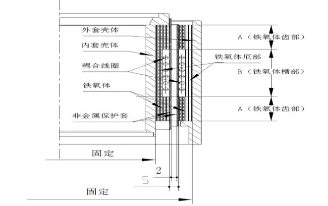
Figure 1: Coupler structure size diagram
Suitable for ferrite in high temperature environment,the initial magnetic permeability of the magnetic core is≥2000, and the saturation magnetic density is ≥200mT;
1.2 Simple Model Analysis of Coupler Power Transmission
The mutual inductance model theory based on the principle of electromagnetic induction (Sun, et al, 2005), the non-contact transmission of system energy is realized by ICPT technology. The primary and secondary coils are respectively wound around a relatively separated and coaxial core to form a loosely coupled transformer, the primary coil. The magnetic field is generated by a high-frequency excitation current, and the secondary coil can induce an alternating current signal of the same frequency。
Compared with the ideal transformer, the loosely coupled transformer has the effect of the edge effect on the air gap reluctance when the magnetic circuit is analyzed for the loosely coupled transformer due to the existence of the air gap. For a loosely coupled transformer, the air gap of the ideal transformer is relatively large, the magnetizing inductance is relatively small, and the leakage inductance is relatively large, and the relationship between the voltage and current of the primary and secondary sides does not completely conform to the turns ratio relationship.
1.2.1 Magnetic Circuit Analysis
Using the U-shaped core for formula derivation, the coupler dimensioning and magnetic circuit are shown below.

Figure 2: U core size

Figure 3: Coupler simplified schematic
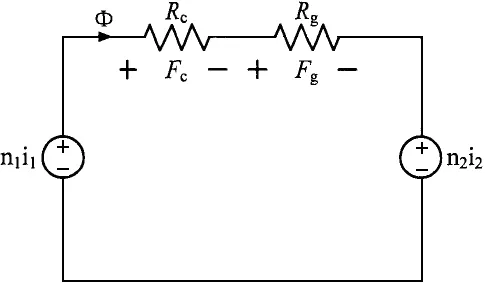
Figure 4: Coupler equivalent magnetic circuit
In the figure, lm is the average magnetic path length, lg is the air gap length, and Rc and Rg are the magnetic core reluctance and the air gap reluctance, respectively.
The concept of a magnetic circuit corresponds in form to the concept of a circuit. A magnetic flux, like the current in a circuit, is always closed and circulates in a path of low reluctance according to the shortest path principle. The closed path through which the flux passes is called the magnetic circuit. The correspondence between the magnetic circuit and the circuit is as follows:

Table 1 Magnetic Circuit Nouns and Codes
1.2.2 Coupling Coefficient Analysis
In order to facilitate the analysis of the energy transfer characteristics of the loosely coupled transformer, the loosely coupled transformer is simplified as follows: the magnetic cores on both sides have the same shape and positional symmetry; the turns ratio of the windings on both sides is 1: 1, the shape is the same, and the position is symmetrical. From the above simplification, it can be considered that the parameters of the loosely coupled transformer have symmetry, the self-inductances L1 and L2 of the windings on both sides are equal, and the leakage inductances L1 and L2 of the windings on both sides are equal.
The T-equivalent model of the loosely coupled transformer is shown in the dashed box (the winding resistance on the winding is ignored in the model) where Lmis the magnetizing inductance or the coupled inductor. When the AC voltage source outputs a sine wave with an angular frequency of ω, the load voltage transmission ratio is analyzed by the AC impedance method. The load voltage transmission ratio is defined as the ratio of the AC voltage amplitude URon the load R to the AC voltage source amplitude UAC. Recorded as Gk.

Figure 5: Loosely coupled transformer T-equivalent model
In order to facilitate the formula derivation, four equivalent impedances of Z0, Z1, Z2, and Z3 are marked at the four ports in the equivalent model diagram, and the impedance values are respectively given by the following formulas.

Then the voltage transfer ratio Gkcan be expressed as

Define Q as the ratio of the self-inductance and the equivalent load R resistance of the primary winding

Under the condition that the parameters of the loosely coupled transformer are constant, the larger the Q value,the smaller the load is, the smaller the resistance of R is. Therefore, the higher the efficiency, the better the quality of the inductor component.
Definition of coupling coefficient K
Define the coupling coefficient of the coupler to

When the turns ratio is 1, the coupling coefficient can be obtained from the above two equations.
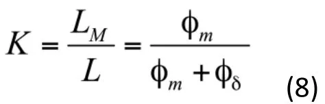
The coupling coefficient can be expressed in the form of magnetoresistance

It can be seen from the above formula that the higher the coupling coefficient, the better the energy transfer performance of the coupler; the air gap size, the number of turns of the coil, the magnetic reluctance of the core and the area of the end and the area of the erection will affect the coupling coefficient.
Therefore, according to the structure, the air gap cannot be zero, here fixed 5mm, and the transmission efficiency of the system is studied from the width of the ferrite tooth, the width of the ridge and the number of turns of the coil.

Figure 6: Functional block diagram of coupled simulation experiment
2. COUPLER SIZE OPTIMIZATION SIMULATION
Based on the Maxwell electromagnetic field finite element simulation platform, the non-contact energy transmission system is simulated from the model establishment, the excitation source application, the boundary condition given to the later cloud image extraction.
2.1 Simulation Modeling
Under the Maxwell simulation platform, the geometric model of the can core is drawn. The outer diameter of the coupler is 170mm, the inner diameter is 100mm, the air gap is 5mm, and the thickness of the ferrite is 4. 2mm.The model sets the soft ferrite core. The magnetic permeability is 2000, and the saturation magnetic density is≥200mT. The conductivity is 0. The boundary conditions for determining the finite element calculation are primary fixed and secondary rotation, and the excitation applied to the primary coil is a high frequency alternating current signal.
Equivalent Circuit:

Figure 7: Coupler equivalent circuit
The coupler simulation model was built using Ansys Maxwell simulation software. Apply a sinusoidal current to the winding, calculate the flux linkage of the primary and secondary windings, respectively, to calculate the inductance parameter of the coupler; short-circuit the secondary winding, apply a sinusoidal current to the primary winding, calculate the flux linkage of the primary winding, and calculate the coupler Short circuit inductance.
According to the calculated circuit parameters, the external circuit is built as shown in Fig. 8. The simulation model of the coupled field circuit coupling is established to calculate the performance of the coupler.

Figure 8: External circuit
2.2 Effect of Groove Width Variation on Transmission Power and Efficiency
The initial size of the single winding adjusts the window width first to obtain different structures and their electromagnetic parameters. In this process, the axial dimension of the coupler remains the same.
The window width was changed from 20mm to 23. 5mm, 27mm and 30mm respectively, and the winding turns were changed from 6 to 7 beams, 8 beams and 9 beams respectively. The four structures of the coupler were simulated separately to obtain the magnetic field distribution and magnetic cloud. Figure and electromagnetic parameters are as follows:

Figure 9: Magnetic field distribution and magnetic dense cloud image with same window width
The windings of the four structures are respectively connected to the alternating current of amplitude 10A, and the maximum magnetic core density of the core is measured to be about 70mT, 72mT, 76mT and 79mT,respectively, all of which are much smaller than the saturation magnetic density of the ferrite of 200mT.
Pspice software is used to bring the electromagnetic parameters of each structure into the simulation circuit diagram. The input voltage is 36V and the frequency is 40KHz. The leakage inductance of the four structures is 3.34uH, 3. 89uH, 4. 44uH and 5. 08uH respectively, and the corresponding compensation resonant capacitance is 4.41uF respectively. , 4. 07uF, 3. 56uF and 3. 12uF, the magnetizing inductances are 39. 33uH, 54. 32uH, 71. 89uH and 91. 97uH, respectively. The copper loss resistance 0.6Ω in the figure is estimated based on the actual coupler test data.
Calculate the output power = U2*U2/8Ω(output power + copper loss), the output power and efficiency of each structure are shown below:
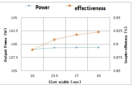
Figure 10: Output power and efficiency curves for different slot widths
2.3 Effect of Tooth Width Variation on Transmission Power and Efficiency
When the windings are 8 bundles, the window width and the number of winding turns are kept unchanged, and the tooth width is changed from 15 mm to 18 mm, 21 mm and 24 mm, respectively, that is, the total length is changed from 57 mm to 63 mm, 69 mm and 75 mm, respectively, and the four structures of the coupler are separately performed. Simulation, the magnetic field distribution, magnetic density cloud map and electromagnetic parameters are as follows:

Figure 11: Magnetic field distribution and magnetic dense cloud diagram of 8 winding
The windings of the four structures are respectively connected to the alternating current of amplitude 10A, and the maximum magnetic core density of the core is measured to be about 76mT, 79mT, 82mT and 84mT,respectively, all of which are much smaller than the saturation magnetic density of the ferrite of 200mT.
The output power, loss and efficiency of each structure are shown in the following table:
The efficiency curve and coupler efficiency curve for different tooth widths are as follows:

Figure 12: 8 Winding efficiency and transmission efficiency with 8 winding
2.4 Fixed 9 Bundle Window Width, Tooth Width Change
When the winding is 9匝, the window width and the number of winding turns are kept unchanged, and the tooth width is changed from 15mm to 18mm, 21mm and 24mm respectively, that is, the total length is changed from 60mm to 66mm, 72mm and 78mm, and the four structures of the coupler are separately performed. Simulation,the magnetic field distribution, magnetic density cloud map and electromagnetic parameters are as follows:

Figure 13: Magnetic field distribution and magnetic dense cloud diagram of 9 winding
The windings of the four structures are respectively connected to the alternating current of amplitude 10A, and the maximum magnetic core density of the core is measured to be about 79mT, 81mT, 85mT and 93mT,respectively, all of which are much smaller than the saturation magnetic density of the ferrite of 200mT. 。

Figure 14: Influence of different tooth widths of 9 winding on output power and coupling efficiency
2.5 Coupler Offset Simulation
In order to simulate the up and down offset of the magnetic core, the simulation model shown in Fig. 15 is established to move the inner cylinder core down by 5 mm.
The resonant capacitor is kept at C=1. 11uF, and the load characteristics of the coupler are calculated as shown in Table 2.

Figure 15: Coupler simulation model

Table 2 Coupler load characteristics (Resonant capacitor C=1. 11uF)
After the inner cylinder core is moved down by 5 mm, the short-circuit inductance of the coupler actually becomes Lk=17. 50uH, and when the inner cylinder core is shifted by 5mm, the output voltage and efficiency vary with the load as shown in Fig. 16 (the abscissa is the load resistance unit Ω). The ordinate is the voltage unit V). If the original resonant capacitor is still maintained at 1. 11uF, the output voltage and efficiency will be small; but if the resonant capacitor is re-selected, the output voltage will increase even higher than the original value, and the efficiency will be slightly improved, but still lower than the original value.
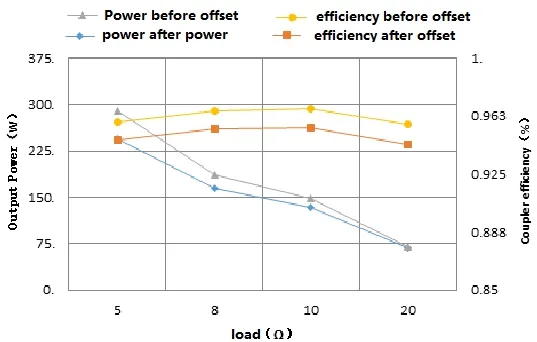
Figure 16: Output voltage-load characteristics
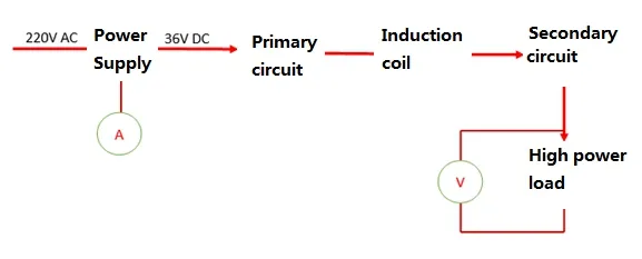
Figure 17: Schematic diagram of the experimental test of the coupler
3. LAB TESTING
Under the conditions of the laboratory, the primary circuit for non-contact power transmission by inputting 36V DC voltage is processed by the primary circuit into AC and then transmitted to the secondary circuit through the induction coil. The secondary circuit is connected to a 10Ω high-power resistor. Measuring the current at the input and the voltage of the load can get the input power and output power, which can calculate the efficiency of the whole transmission system.

Figure 18: Influence of the variation of axialdisplacement of magnetic ring on coupling efficiency
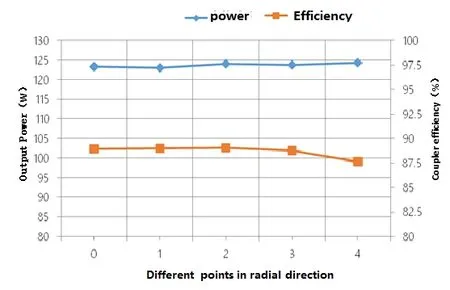
Figure 19: Influence of radial offset on transmission efficiency
Figure 18 shows that the inner and outer magnetic rings are most efficient at a fixed location, and the efficiency is reduced at both points of efficiency. According to the existing model, the inner and outer magnetic rings are the most efficient at the -3 position, and the efficiency is not less than 85% in the range of -8 to +2, and the power is not less than 120W. Therefore, the actual application efficiency point is required as the installation point.
At the 0 o'clock position, the inner magnetic ring is at the center position of the outer magnetic ring, and 1/2/3/4 respectively represents the point 90° apart on the circumference, and the data measured at the time when the outer magnetic ring is in contact with the state. It can be seen that the radial offset does not have much influence on power and efficiency. As far as practical application is concerned, there is no mechanical interference.

Table 3 Output with the inner and outer magnetic rings rotate
When the inner magnetic ring rotates coaxially with respect to the outer magnetic ring, the input and output have response fluctuations. The input and output fluctuations remain basically unchanged when the speed is changed,indicating that the rotation itself has little effect on the input and output, and the input and output. The transformation may be caused by the uneven magnetic or axial set, which can be further tested here.

Table 4 Output with the inner and outer magnetic rings immerse in water
As can be seen from the above table, due to the different magnetic permeability of liquid and air, the measurement results have a relatively large influence, and the output power and efficiency in air are higher than in water. Therefore, the experimental results in the air need to be verified under the conditions of water immersion.
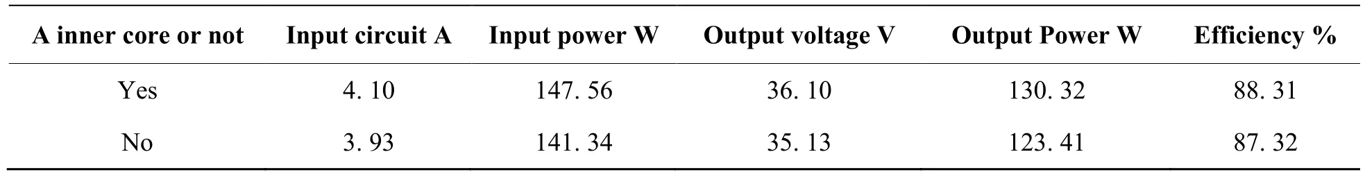
Table 5 Output with a iron core or not
The same principle, due to the different magnetic permeability of the iron core and air, has a relatively large impact on the measurement results. The output power and efficiency are higher in the center than in the air.
CONCLUSIONAND SUGGESTION
In this paper, the magnetic coupling energy transmission system of the downhole rotary guiding system is modeled and analyzed, and the main factors affecting the transmission efficiency and output power and its main theoretical models are compared and analyzed. Through the comparison of experimental data, the following conclusions can be obtained:
a) The coupling coefficient K is the ability to characterize the energy transfer of the coupler. In the same condition, in order to increase the K value of the coupling coefficient, the air gap can be minimized and the permeability of the ferrite can be improved within the engineering allowable range. Rate, increase the core end face area and the core area;
b) Transmission efficiency and maximum output power can be effectively improved by compensating capacitors;
c) The compensation capacitor is sensitive to the coupled magnetic circuit. In order to achieve the best effect, it is necessary to match the compensation capacitor. In the case of downhole vibration, it is necessary to debug a wider working area;
d) The maximum transmission efficiency and the maximum output power do not coincide. The compensation capacitor has limited improvement in the transmission efficiency of useful work. In fact, the main function is to increase the maximum output power.
The above conclusions have a good guiding significance for the development of non-contact energy transmission systems, but it is necessary to further determine the influence laws and scope of the following factors:
· The effect of the actual effective space downhole on the coupled magnetic circuit and its extent;
· The influence of effective magnetic flux and compensation capacitance on the working area and its law;
· The maximum transmission efficiency should consider the influence of the latter stage circuit on the virtual power compensation capability, thus taking into account the maximum output power.
 Advances in Petroleum Exploration and Development2019年2期
- Advances in Petroleum Exploration and Development的其它文章
- Description of Shale Pore Fracture Structure Based on Multi-Fractal Theory
- Comparative Analysis of Abnormal Pore Pressure Prediction Models for Niger Delta Oil and Gas Fields Development
- Development of a New Model for Leak Detection in Pipelines
- Optimizing Production in Brown Fields Using Re-Entry Horizontal Wells
- Economic Analysis of Low Salinity Polymer Flooding Potential in the Niger Delta Oil Fields
- Using Shallow Platform Drilling Technology to Tap the Reserves of the Below Constructed Area of Fuyu Oilfield:Taking Chengping Block 12 as an Example