
Five-Section Trajectory Design of Thick Glutenite Reservoir in Shengli Oilfield
2019-08-04 08:45DOUYulingTANGZhijunXUYunlongWANGJingshuang
DOU Yuling; TANG Zhijun; XU Yunlong; WANG Jingshuang
[a] Drilling Technology Research Institute of Sinopec Shengli Oilfield Service Corporation, Dongying, Shandong, China.
[b] Sinopec Shengli Oilfield Branch Corporation, Dongying, Shandong, China.
Abstract Many blocks of Shengli Oilfield are located in urban areas, and the site selection of well sites is limited. In order to meet the needs of reservoir development and deployment, five-section trajectory is increasingly used. Difficulty in site selection results in directional well development,and reservoir deployment requires vertical well development. In order to resolve the two contradictions, five-section trajectory is used in the well design, and vertical drilling after hitting the target. The problems with this type of trajectory are high torque drag and easier fatigue of the drilling pipe. When the displacement is small, the effect is small. When the displacement is large,it will cause engineering complexity such as difficulty drilling weight transfer and fatigue of drilling pipe. Aiming at the shortcomings of the five-section trajectory, with the help of existing drill string force analysis software, the parameters of the five-section trajectory were analyzed,and reasonable values were recommended to provide an optimization idea for the five-section trajectory.
Key words: Shengli Oilfield; Directional well; Thick glutenite; Five-section; Well trajectory;Design
1. FOREWORD
Most blocks of Shengli Oilfield are located in urban and rural areas. Considering environmental protection, public safety and other factors, drilling site selection is difficult, so directional wells have become common well types,and because of limited surface site selection, the proportion of highly deviated wells is increasing . However, from the perspective of reservoirs, it is desirable to use vertical wells for reservoirs with thick oil layer, because directional wells will make the interval between underground wells less uniform when the thickness of the reservoir is larger, as shown in Figure 1. This effect becomes more serious, especially when the well angle is relatively large, and may even lead to the failure of the entire reservoir development. For example, in the case of water injection development, because the wells at the top of the reservoir are too close, the reservoir will be flooded in advance.
Difficulty in site selection results in directional well development, and reservoir deployment requires vertical well development. In order to resolve the two contradictions, five-section trajectory is used in the well design, and vertical drilling after hitting the target. The problems with this type of trajectory are high torque drag (Li, et al,2018; Wang, et al, 2016; Chen, et al, 2018; Cheng, 2013; Wang, 2016; Du, 2017), and drilling pipes are more prone to fatigue. When the displacement is small, the effect is small, but when the displacement is large, it will cause engineering complexity such as difficulty drilling weight transfer and fatigue of drilling pipe. In view of this,this article takes the development of a thick glutenite reservoir in a block of Shengli Oilfield as an example. Based on torque drag analysis and fatigue analysis, a five-section trajectory optimization is carried out to reduce the drilling difficulty and shorten the well construction period (Gai, 2018; Liu & Feng, 2003; Wang & Wan, 2004;Wang, et al, 2018).
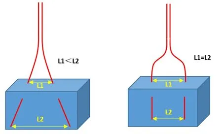
Figure 1: Schematic diagram of underground well spacing of different trajectory types
2. BLOCK OVERVIEW
The block is located in the eastern section of the northern zone of the Dongying Sag. The main oil-bearing section is the glutenite body in Es4Formation, with a buried depth of 3710 ~ 4300m. Reservoir features: many layers,large thickness, and long oil-bearing well sections. Reservoir analysis suggests that straight wells are more adaptable, and multi-stage fracturing is beneficial to increase productivity. Taking into account the later well pattern adjustment, the row well pattern encryption adjustment is flexible, and the block adopts the row well pattern. Well pattern direction: well rows are in the same direction as fractures, and the designed row spacing is 225m and well spacing is 450m, as shown in Figure 2.
Because of ground reasons and the need for later management, the old well site and the "well factory model" are used. In order to meet the needs of the reservoir, the trajectory type uses a five-sectiontrajectory, which is drilled vertically after the target. A total of 12 new wells are deployed in the plan, and the displacement is 225m-1070m.
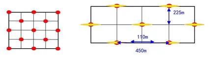
Figure 2: Schematic diagram of row-shaped well pattern
3. OPTIMIZATION OF FIVE-SECTION WELLBORE TRAJECTORY
The five-section (hold-build-hold-drop-hold) wellbore trajectory can meet the needs of both surface location and reservoir vertical well development. For wells with displacements close to and exceeding 1000m, the five-section trajectory will significantly increase torque and drag . The parameters that affect the shape of the five-section trajectory mainly include the length of the final hold, Kick-off point, build-up rate, and the final inclination.
3.1 Impact of the Length of the Final Hold on Engineering
In the case of the same Kick-off point and build rate, if the vertical depth of the reservoir required to be reduced to 0 ° is different, the length of the final hold is different. Welltrajectories have been designed for different targets requirements (figure 3).

Figure 3: Well trajectories of different target requirements
With the help of Landmark software, the torque drag in the drilling corresponding to different trajectories is analyzed, as shown in Table 1.

Table 1 Analysis of the influence of the final hold section on the torque drag
The results show that the longer the lengths of the final hold, the longer the length of the wellbore, the larger the maximum inclination, and the larger the torque and drag. Compared with the three-section trajectory(hold-build-hold), when the final hold is 550m, the torque increases by 7%, the drag of pick-up increases by 18%,and the drag of slack-off increases by 10%, and when the final hold reaches 850m, the torque increases by 22%,the drag of pick-up increases by 44%, and the drag of slack-offincreases by 24%.
3.2 Kick-Off Optimization
The Kick-off point is generally selected in a relatively stable formation, avoiding rock fracture zones and lost formations, which is conducive to the stability of the wellbore in the build section. The cluster well group must also consider the collision; and the needs of the oil recovery process also need to be considered. From bottom to up the well encountered the formation Shahejie, Dongying, Guantao, Minghuazhen and Pingyuan. The burial depth of the Minghuazhen Formation is 1075m. Considering the stability of the formation, the Kick-off point is selected to be deeper than 1075m.
In the five-section trajectoty, with the same other parameters, as the Kick-off point deepens, the maximum inclination increases and the well depth increases. See Table 2 for analysis of torque and drag during drilling at different Kick-off points.
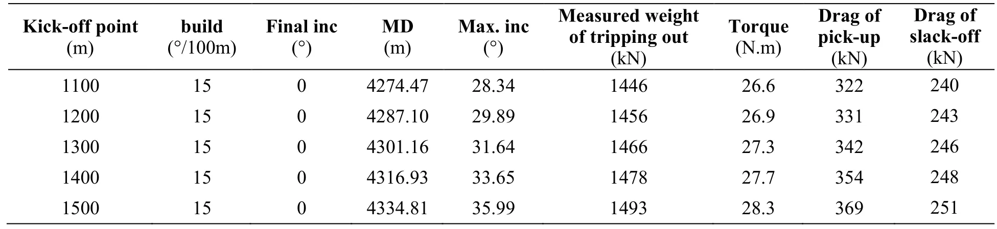
Table 2 Drill string force analysis results at different kick-off points trajectory
The calculation results show that as the depth of the Kick-off point increases, the torque and drag increase, but the increase is not big. Although the effect of the depth of the Kick-off point on the torque and drag is not particularly obvious, considering that the increase of the maximum inclination will lead to an increase in the subsequent drop, which will increase the drillingtime. Therefore, the Kick-off point should not be too deep and should be minimized Maximum inclination.
3.3 Build Rateoptimization
The build rate mainly considers the following factors: First is the requirements of the oil production process;second is the ability of the power drilling tool to build in different formations and different boreholes; the third is the influence of the build rate on the torque drag and stress of drillpipe.
If the build rate is too low, it will increase the length of the build section and increase the workload of the build process, which is not conducive to improve the efficiency. If the build rate is too high, it will increase the dogleg and increase the wear of the oil production string in the later stage. The drill string force analysis was performed(Table 3): Kick-off point is1200m, vertical drilling behind the target, build rate: 10 ° / 100m, 12 ° / 100m, and 15 °/ 100m.The analysis results show that because the change of the build rate has no significant effect on the well inclinatione and well depth, it has little effect on torque and drag, but the change of the fatigue ratio of the build section is obvious.
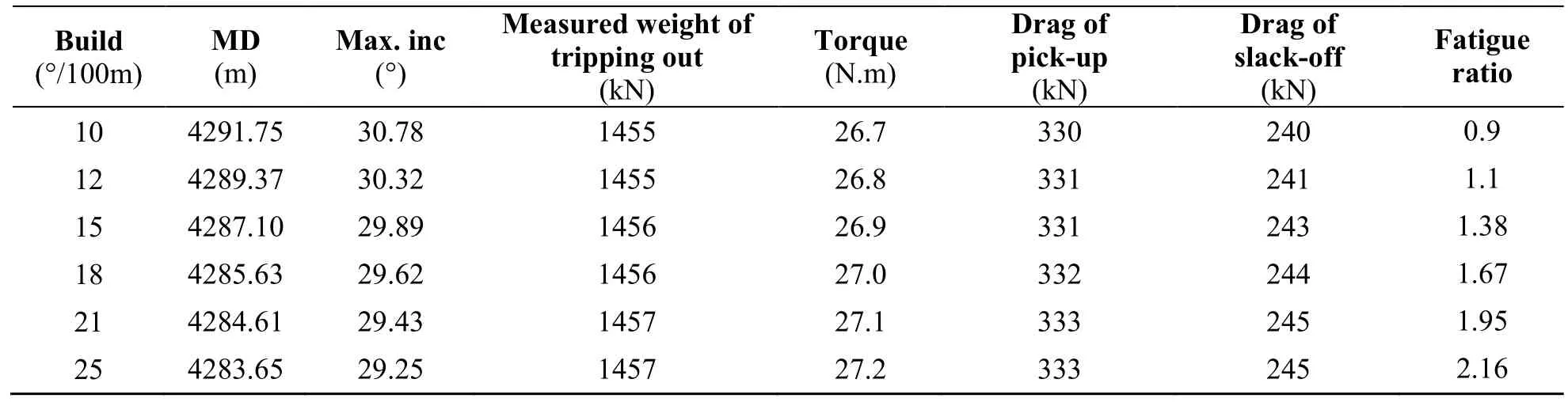
Table 3 Stress analysis results of drill string with different build rates

Figure 4: Analysis of fatigue ratio of drill string with different build rates
3.4 Final Inclination Optimization
In order to realize the deployment of underground vertical well patterns, Geologist hopes to drill vertically after the target, that is, to drill hold after the target at the inclinaiton of 0°. However, this requirement will lead to an increase in torque and drag.The stress of the drill string under the different final inclination was analyzed (table 4).The torque and drag which is at final inclination 6 °, 8 °, and 10 °is biggerthan at final inclination0 °. The drag increase is 4% to 10%, and the torque increase is 3% to 5%.The theoretical analysis assumes that the wellbore is smooth, so the increase in torque drag is not large. But in actual drilling, because the drilling speed is slower during the drop process and the wellbore immersion time is increased, it will cause the wellbore quality to decrease.And at the same time, dropping increases the irregularity of the wellbore, which will increase the torque drag in the drilling process.In order to reduce the difficulty of drilling operation, and at the same time consider the reservoir well pattern, the final inclination can be reasonably designed in consideration of the oil layer thickness of each well and the difference in distance between the top and the bottom of the reservoir.As shown in Figure 5,the thickness of the oil layer is 400m, and the allowable distance between the top and bottom of the oil layer is not greater than 50m. It can be calculated that the final inclination should be less than or equal to 7.1 °. Then the final inclinaiton can be designed with a 7 ° to avoid the 0 °, and it can make the drilling easier.

Table 4 Stress analysis results of different final inclinaiton trajectory
Figure 5: Schematic diagram of oil layer thickness and allowable displacement difference
4. CASE
Taking the well Y-X4 completed in the early stage of the block as an example, the wellbore trajectory was redesigned using the optimization ideas in the text.After optimization, the torque is reduced by 13%, the pick-up drag is reduced by 18%, and the slack-off drag is reduced by 14%.The main reason is that the length of the final hold is reduced. At the same time, a small-degree is used instead of a zero-degree as the final inclinaiton. Due to the decrease in the build rate, the fatigue ratio is reduced from 1.41 to 1.11, which can greatly reduce the fatigue risk of the drill string.

Table 5 Comparison of data before and after optimization
CONCLUSIONS
(1) When the displacement is close to or more than 1000m, compared with the three-section trajectory, the five-section trajectory will obviously increase the torque drag during drilling.
(2) Although the effect of the depth of the Kick-off point on the torque drag is not obvious, the increase of the Kick-off point depth will lead to the increase of the maximum inclination, and the increase of the inclination will lead to the increase of the work load of the later dropping operation. Therefore, the depth ofKick-off point should not be too deep, the maximum inclination should be controlled within 30°.
(3) The drilling period of the five-section trajectory is longer than that of the three-sectiontrajectory. The fatigue risk of the drill string is relatively increased. To reduce the fatigue of the drill string, the build rate should be controlled within 12 ° / 100m.
(4) When reservoir conditions permit, try to avoid 0 ° to be the final inclination. According to the thickness of the oil layer and the needs of the well pattern, use the small angle as final inclination.
 Advances in Petroleum Exploration and Development2019年2期
- Advances in Petroleum Exploration and Development的其它文章
- Description of Shale Pore Fracture Structure Based on Multi-Fractal Theory
- Comparative Analysis of Abnormal Pore Pressure Prediction Models for Niger Delta Oil and Gas Fields Development
- Development of a New Model for Leak Detection in Pipelines
- Optimizing Production in Brown Fields Using Re-Entry Horizontal Wells
- Economic Analysis of Low Salinity Polymer Flooding Potential in the Niger Delta Oil Fields
- Using Shallow Platform Drilling Technology to Tap the Reserves of the Below Constructed Area of Fuyu Oilfield:Taking Chengping Block 12 as an Example