
Cascaded plasmonic nanorod antenna for large broadband local electric field enhancement∗
2019-11-06 00:46DouZhang张豆ZhongJianYang杨中见andJunHe何军
Chinese Physics B 2019年10期
Dou Zhang(张豆),Zhong-Jian Yang(杨中见),and Jun He(何军)
Hunan Key Laboratory of Super Microstructure and Ultrafast Process,School of Physics and Electronics,Central South University,Changsha 410083,China
Keywords:surface plasmon,optical antenna,electric field enhancement,broadband,cascaded
1.Introduction
With the development of plasmonics,the optical nanoantennas have aroused a lot of research interests.[1–3]Optical nanoantennas are the analogues of classical radio frequency antennas. Optical nanoantennas can concentrate the light from free space to the nano-sized local field and strongly modify the light–matter interactions. This occurs due to the fact that there are strong surface plasmon resonances(SPRs)on the antennas.[4]The enhanced local electric fields in the plasmonic nanoantennas have many applications such as in surface-enhanced Raman scattering(SERS),[5,6]fluorescence emission,[7–9]metasurface,[10,11]and nonlinear optics.[12–14]The SPR of plasmonic nanostructure is highly dependent on its material,[15,16]ambient environment,[17–19]and especially its geometry.[20,21]Thus,lots of metal optical antennas with various shapes have been proposed such as single nanorods,[3,22–24]two-wire antennas,[25–29]bowtie antennas,[7,30,31]nanodisks,[32]spheres antennas,[33,34]nanotube antennas,[35]cross antennas,[36–38]and split-ring antennas.[39–41]Among these antennas,the two-wire antenna is the most common antenna in structure.The two-wire optical antenna is a dimer structure where the two nanowires are endto-end aligned with a narrow gap,[3]This antenna has been widely investigated due to the fact that its structure is simple and can be easily fabricated in experiment,while it can create strong electric near-field enhancement inside the gap.
Varying the geometry of antenna is widely carried out to obtain high enough field enhancement,where the most efficient way is to reducing the gap size of an antenna.[29,42]Varying the size of an antenna has also been studied.For a twowire antenna,it has been shown that its size can be optimized to obtain the maximal near field enhancement with a given gap size and working wavelength.[29]This size optimization is highly related to the balance between the light extinction capability and field concentration size of the antenna. Integrating nanoantennas with other nanophotonic structures has also been studied,where the local field of the nanoantenna can be largely increased.[18,43–46]The above strategies are used to optimize the field enhancement at a single resonance position,which works well for some applications,for example,the SERS.For some other applications such as in fluorescence and nonlinear optics,the optical response is required to be optimized at multiple wavelength,where the further improvement is still needed.In the emitter-plasmon coupled system,it usually requires high field enhancement not only at the excitation wavelength but also at the emission wavelength,as a high field enhancement usually shows an enhanced emission property.At the same time,a certain gap size of an antenna is required to avoid quenching effect.[47]Thus,constructing an antenna exhibiting large broadband field enhancement with a certain gap size will benefit the enhanced spectrum of emitterplasmon coupled system.There are a few investigations where broadband field enhancement can be obtained and the spectral bandwidth is as large as ∼700 nm.[48]But,the field intensity enhancement value there(∼1700 for gap size 10 nm)is lower than that of common antennas.
In this work,we introduce a cascaded nanorod antenna for large broadband electric near field enhancement.The structure has two big gold nanorods placed on the two sides of a small two-wire antenna. The small antenna consists of two small gold nanorods.The extinction cross section of the big nanorod is stronger and broader than that of the small nanorod.However,As it has been mentioned above,a two-wire antenna with big nanorod does not necessarily show higher near field enhancement than that of small nanorod.[29]On the other hand,our previous work has shown that for a coupled system with a big and a small nanorod,the efficient energy transfer from the big nanorod to the small one can occur due to the strong plasmon mode interactions.[49]This gives rise to enhanced and broadened optical response(absorption/extinction cross section)of the small nanorod. These previous results indicate that in a cascaded nanorod antenna,the light extinction response of the small antenna can be enhanced and broadened,resulting in significantly larger and broader electric field enhancement than in an individual small two-wire antenna.Here we will show that our calculations confirm the above point.Furthermore,the high tenability and quantum efficiency of the cascaded antenna will also be discussed.
2.Results and discussion
Here,we first investigate a coupled structure of a big Au nanorod and a small Au nanorod which is schematically shown in Fig.1(a).The system is excited by a plane wave polarized along the nanorods.The simulations are carried out by using the commercial finite-difference time-domain(FDTD)software(Lumerical FDTD).The dielectric constants of Au are taken from Palik’s book.[50]Figure 1(b)shows the absorption cross section of an individual small Au nanorod,an individual big Au nanorod,and the small Au rod in the coupled structure.Here,the absorption cross section of the small nanorod in the coupled structure can be calculated directly by setting a power monitor box that covers only the small nanorod.[49]The size of the big nanorod and small nanorod and the gap between them are chosen based on the fabrication accuracy and the relevant optimized size for a two-wire antenna.[29]It can be easily verified that the absorption and scattering dominate the response of the small nanorod and big nanorod,respectively. This is due to the fact that the ratio of absorption to scattering for a plasmonic nanostructure is closely related to the size of the structure.[51]The peak on the spectrum of each individual rod corresponds to an electric dipole plasmon resonance.The two plasmon resonances are spectrally close to each other.
The absorption cross section of the small Au rod in the coupled structure is significantly increased compared with the individual case. Furthermore,the spectrum of the small nanorod is widened significantly.The optical spectrum of the whole system is modified obviously as a result of the strong plasmon coupling although the optical response of the individual small nanorod is much smaller than that of the individual big one(Fig.1(c)).The giant modification of the optical absorption of the small rod(both amplitude and width)in the coupled structure(Fig.1(b))is caused by the energy transfers between the strongly coupled plasmon modes of the two nanorods. Similar results and more detailed discussion can be found in our work about the coupled orthogonal plasmonic nanorod resonators.[49]The evidences of energy transfer behaviors based on the calculations of the near-field responses in time domain and far field spectra can be easily given according to Ref.[49].So we shall not repeat it here.The peak of the small nanorod also shows a redshift,which is due to the well-known plasmon hybridization.[52]The enhanced and broadened optical response means the giant modification of the effective light extinction capability of the small nanorod,while its field concentration size is not changed.This fact is the foundation for the constructing a cascaded antenna.

Fig.1.(a)Schematic diagram of a coupled structure with length,width,and height for small Au rod being LS=55 nm,WS=10 nm,HS=10 nm,and for big Au nanorod being LB=150 nm,WB=50 nm,HB=50 nm,respectively,and gap size being 15 nm.(b)Absorption cross section of individual small nanorod,individual big nanorod,and small nanorod in the coupled structure.(c)Extinction cross section of individual small Au nanorod,individual big Au nanorod,and coupled structure.
Now we come to investigate the electric field intensity enhancementof a cascaded antenna consisting of a pair of small Au nanorods and a pair of large Au nanorods.The schematic diagram of cascaded nanorod antenna structure is shown in Fig.2(a).The parameters of the big Au nanorod and the small Au nanorod are the same as those in Fig.1. The gap between the two small Au nanorods is fixed at 15 nm.We refer to the small nanorod dimer as the small antenna. Figure 2(b)shows the|E/E0|2distribution on the x–z plane of the cascaded antenna at the resonant wavelength(λ=800 nm).The distribution pattern around the small nanorods in the cascaded antenna is almost the same as that in the individual small antenna,namely,each nanorod has an electric dipole plasmon on it.However,the field intensity is clearly enhanced around the small nanorods compared with around the individual small antenna.Note that based on the result in Ref.[29],it can be easily checked that the field intensity enhancement of a twowire antenna with the big nanorods is smaller than that with small ones.Thus,the results of small antenna are shown here for comparison.
In order to quantitatively present the field intensity enhancement and the spectral response of the cascaded antenna,we calculate the spectrum of the|E/E0|2in the gap center of small antenna.For comparison,we also calculate the|E/E0|2in the gap center of the individual small antenna(Fig.2(c)).The resonant|E/E0|2of the cascaded antenna(∼5330)is more than 3 times higher than that of the individual small antenna(∼1730). In addition,the spectrum of the cascaded antenna becomes wider. The full width at half maximum(FWHM)of the cascaded antenna(∼110 nm)is about twice as large as that of the individual small antenna(∼50 nm).Figure 2(c)also illustrates the optimized|E/E0|2of the two-wire antenna for the resonance at λ=800 nm as the reference.Here the optimized value means the maximum field intensity enhancement achievable by a two-wire antenna at a given wavelength with varying the length and width(height),while the gap size is fixed.[29]The corresponding nanorod has a length and width of 91 nm and 18 nm,respectively.The gap of rods is also 15 nm.The corresponding resonant value and the spectrum width are ∼3500 and ∼50 nm,respectively.It is seen that the resonant value and the spectrum width of the cascaded antenna are both larger than those of the optimized two-wire antenna.
Now,we turn to the study of the effects of the geometrical parameters on the field intensity enhancement of the cascaded antenna.Figure 3(a)shows the|E/E0|2spectra in the gap center of the cascaded antenna with different lengths of the big Au nanorods. The other geometric parameters are the same as those in Fig.2. With the length of the big Au nanorod increasing from 100 nm to 160 nm,the resonant position of the electric field intensity shows a slight redshift.The resonant field intensity value reaches a maximum value at L=130 nm,but it decreases slightly for other lengths.On the other hand,the width of the spectrum is broadened with the increase of the length of the big Au nanorod,and the FWHM increases from 50 nm to 140 nm with the length varying from 100 nm to 160 nm. This is caused by the fact that the coupling strength increases with the length increasing,[49]and the spectrum width of a nanorod increases with its size augment.
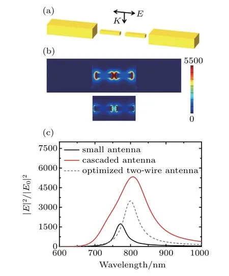
Fig.2.(a)Schematic diagram of cascade antenna structure with geometry of big and small nanorods being the same as those in Fig.1,and gap between two adjacent Au nanorods being 15 nm.(b)Resonant electric field intensity distribution of cascaded antenna(top)and individual small antenna(bottom).(c)Spectrum of field intensity enhancement in gap center of individual small antenna(black),optimized two-wire antenna(dashed),and cascaded antenna(red).
Figure 3(b)shows the field intensity enhancements of the cascaded antennas with varying the sizes of the small nanorod.It is found that the resonance position of the cascaded antenna is highly dependent on the geometry of the small antenna.And as is well known,the resonance position of the small antenna is closely related to the ratio of the length to width(height)of the small nanorod.Thus,for comparison,we focus on the resonance of the cascaded antenna at λ=800 nm and the length and width of the small Au nanorod are changed accordingly.Here the height is kept the same as the width.As the size of the small Au nanorod becomes small,the resonant field intensity of the cascaded antenna increases significantly.This is mainly due to the fact that the small nanorod can obtain energy from both the big nanorod and the plane wave. The ratio of the energy obtained from the big nanorod to that from the pure plane wave excitation increases with the size of small nanorod decreasing.

Fig.3.(a)Field intensity enhancements varying with wavelength for different lengths of big Au nanorod.(b)Field intensity enhancements varying with wavelength for different sizes of the small Au nanorod,i.e.,Width W and height H both are 8 nm,10 nm,12 nm,15 nm and the corresponding lengths are L=47 nm,54 nm,60 nm,68 nm,respectively.(c)Field intensity enhancements varying with wavelength for different gap sizes of small antenna.
As the gap size has strong effect on field intensity enhancement of the small antenna,we also calculate the field intensity responses of the cascaded antenna with different gap sizes of the small antenna(Fig.3(c)).The other parameters are kept the same as those in Fig.2.As expected,the resonant field intensity of the cascaded antenna increases significantly with gap size decreasing. A slight redshift of the resonance wavelength is also seen.This is due to the well-known plasmon hybridization phenomenon.[52]The spectral width,however,does not show obvious variation with gap size.This is because the width is mainly affected by the coupling between the big and small nanorod,which is not changed with the decrease of the gap size between two small nanorods.It is seen from the results in Fig.3 that our proposed cascaded configuration is also applicable for various geometries.

Fig.4.Variations of quantum efficiency with wavelength for cascaded antenna(solid blue)and small antenna(dashed blue).Variations of radiative decay rate enhancement with wavelength for cascaded antenna and small antenna(black).
Due to the occurrence of big nanorods,the overall scattering strength of the cascaded antennas becomes much stronger than that of the small antenna.This could bring new features to the cascaded antenna in terms of modifying the emission property of an emitter nearby. Figure 4 shows the radiative decay rate enhancement of an electric dipole emitter placed in the gap center of a cascaded antenna.The radiative decay rate enhancement is defined as Γr/Γ0,where Γris the radiative decay rate for the electric dipole emitter in the cascaded antenna,and Γ0is the decay rate for an isolated dipole emitter.[7]Here the cascaded antenna is the same as that in Fig.2,and the emitter is polarized along the antenna(x aixs).Comparing with the small antenna,the radiative decay rate of the cascaded antenna is enhanced due to the occurrence of big nanorods.The width of the spectrum also becomes larger.The quantum efficiency of a cascaded antenna is also calculated(Fig.4).Quantum efficiency is defined as Γr/(Γr+Γnon),[7]where Γnonis the nonradiative decay rate for the electric dipole emitter in the cascaded antenna.The quantum efficiency of the cascaded antenna is over 50%in a wide range around the resonance position,and this quantum efficiency is much larger than the quantum efficiency of the small antenna.For example,the resonant quantum efficiency of the cascaded antenna is 59.8%which is more than 7 times higher than that of the small antenna(8.2%).
In experiment,these cascaded antennas are usually fabricated on substrate.So we discuss the case of a cascaded antenna on a substrate.Figure 5(a)shows the schematic diagram of a cascaded antenna placed on SiO2substrate with index n=1.5.Here the bottom of both the big and the small nanorod here contact the substrate,which is a bit different from the previous configuration(Fig.2).The slight change of the configuration has ignorable effect on the|E/E0|2result.The geometry of the cascaded antenna is the same as that in Fig.2.Figure 5(b)shows the|E/E0|2spectrum of the small antenna and the cascaded antenna on the substrate.Comparing with the case without substrate(Fig.2),here the electric field intensity becomes small and the resonance redshifts a lot.These substrate effects have been reported in other similar systems.[29]On the other hand,the electric field intensity enhancement of the cascade antenna is still greatly improved compared with that of the small antenna structure with substrate. Note that the field enhancement of an antenna could be additionally increased by varying its ambient environment,[18,43–46]and the value could be larger than that of our cascaded nanorod antenna.But those structures are not individual subwavelength nanoantennas anymore.If the ambient environment of the cascaded antenna here is properly changed,one can also expect the field intensity to have an additional increase of the field intensity.

Fig.5.(a)Schematic diagram of cascade nanorod antenna on substrate with n=1.5,and(b)field intensity enhancement spectrum in gap center of cascaded antenna(red)and individual small antenna(black).Sizes of big and small rods are the same as those in Fig.2.
3.Conclusions
In this work,we design a cascaded antenna with a big nanorod on each side of a small two-wire antenna.The field intensity enhancement of the cascaded antenna is more than 3 times larger than that of the common two-wire antenna.And the spectral response of the cascaded antenna can become more than twice wider. By changing the geometrical parameters of the system,we demonstrate the high tunability of field intensity spectrum of the cascaded antenna.It is also found that the field enhancement value is more sensitive to the geometry of small nanorod(size and gap),while the width of the field spectrum is more sensitive to the geometry of big nanorod.The quantum efficiency of our cascaded antenna is also investigated.The quantum efficiency can reach more than 7 times larger than that of the small antenna.The features of the field intensity spectrum and the quantum efficiency of the cascaded antennas indicate that they have important potential applications in field-enhanced spectroscopies.

- Chinese Physics B的其它文章
- Compact finite difference schemes for the backward fractional Feynman–Kac equation with fractional substantial derivative*
- Exact solutions of a(2+1)-dimensional extended shallow water wave equation∗
- Lump-type solutions of a generalized Kadomtsev–Petviashvili equation in(3+1)-dimensions∗
- Time evolution of angular momentum coherent state derived by virtue of entangled state representation and a new binomial theorem∗
- Boundary states for entanglement robustness under dephasing and bit flip channels*
- Manipulating transition of a two-component Bose–Einstein condensate with a weak δ-shaped laser∗