
Parameter identification and state-of-charge estimation approach for enhanced lithium–ion battery equivalent circuit model considering influence of ambient temperatures*
2019-11-06 00:46HuiPang庞辉LianJingMou牟联晶andLongGuo郭龙
Chinese Physics B 2019年10期
Hui Pang(庞辉),Lian-Jing Mou(牟联晶),and Long Guo(郭龙)
School of Mechanical and Precision Instrument Engineering,Xi’an University of Technology,Xi’an 710048,China
Keywords:lithium–ion battery,parameter identification,state of charge,ambient temperature
1.Introduction
Recently,lithium–ion batteries(LIBs)have been widely and extensively used in electric vehicles(EVs)due to their merits such as high energy density,no memory effect,low selfdischarge,and long lifespan as opposed to the other types of batteries including lead acid,nickel metal hydride,and nickel cadmium.[1–6]To guarantee the safe and reliable operation of battery packs,it is essential to provide accurate and prompt battery state information like terminal output voltage(TOV)and state of charge(SOC)through battery management system(BMS).Moreover,it should be noticed that due to variable operating conditions for EVs,especially at higher or lower ambient temperatures,battery capacity,internal resistance,and other parameters will accordingly change,which brings about some difficulties in predicting the battery internal stats and SOC.
To estimate battery SOC,many scholars have developed various model-based estimation approaches like electrochemical models[7–10]and equivalent circuit models(ECMs).[11–14]Here in this paper,the electrochemical models are based on the first-principles theory,which describe the micro-reactions inside LIBs in depth,and have a clearer physical meaning.However,they have a complex structure based on partial differential equations,often necessitating model simplification or reduction.[8,15,16]The ECMs are commonly used in the BMS because they can reduce the complexities in parameter identification,SOC estimation,and control design for battery various operations.Nevertheless,the parameters of the ECMs are derived from empirical electric circuit structure and have no immediate electrochemical meaning,which could cause larger errors especially at low SOC region.[17,18]
Besides,in recent years,many studies on the battery temperature have been found in the relevant literature.[19–22]Chuang et al.[19]proposed a temperature-compensated model of lithium–ion polymer batteries for SOC estimation in medical devices by considering temperature effects in a range from 37∘C to 40∘C.Liu et al.[20]designed a temperaturecompensated battery model with a dual-particle-filter estimator to improve the SOC estimation against parameter perturbations caused by the ambient temperature and noise interference caused by the drift current. Lu et al.[21]proposed an integrated SOC algorithm that combines an advanced amperehour counting method and multistate open-circuit voltage(OCV)method.Luo et al.[22]proposed an offset item to develop the observer equation in the estimation model to address the precision at lower ambient temperatures.Therefore,it is easily concluded that ambient temperature is a considerable factor for battery TOV and SOC estimation.
However,a few of issues have been rarely discussed in the existing literature. First,the variation of OCV–SOC is practically dependent on the ambient temperature,while it is usually ignored.In other words,the OCV–SOC relationship at a certain temperature would yield a lager error if it is employed in the other ambient temperature.Second,the battery parameter,especially battery impedance,is greatly affected by the ambient temperature.[23]Yet,it is always assumed to be a constant in most of the existing literature. Third,the differences between the OCV–SOCs for a battery under charge and discharge conditions are seldom considered and discussed in previous literature,and the hysteresis phenomena of battery OCV are usually neglected during different cycles.
To address these problems,Xing et al.[24]developed an off-line OCV–SOC temperature table based on the internal resistance model to describe only the effects of ambient temperature on OCV.The experimental results indicated that the estimation based on the developed model provides more accurate SOC with smaller root mean squared error(RMSE)and mean absolute error(MAE)at various temperatures.Yang et al.[25]established a correction scheme for the temperature dependence of OCV,capacity,and resistor–capacitor(RC)parameters in the estimator,but it is only suitable for transient response of LIBs with short time constant.Du et al.[26]established a temperature-compensation model in a wide temperature range from 0∘C to 40∘C,in which fully considered are the effects of SOC and ambient temperature on the Ohmic internal resistance and polarization capacitance,but it did not reflect the effects of ambient temperature on the polarization capacitance with a long time constant.And the OCV hysteresis phenomenon caused by charge and discharge conditions and C-rate was ignored. To sum up,accurate battery model can provide SOC estimation for the model-based SOC estimation method with higher accuracy,especially when considering the influence of ambient temperature.
Consequently,this study focuses on constructing an enhanced equivalent circuit model(ECM)considering the influence of ambient temperature on the open-circuit voltage for a lithium–ion battery,which is derived from the second order resistor–capacitor equivalent circuit model(2RC-ECM).The main contributions of this study are summarized as follows.(i)By considering the influence of ambient temperature characteristics on the electrical dynamics performances of LIBs,a temperature-sensitive resistor Rtempis added to the 2RCECM to describe the change of battery impedance with ambient temperature;(ii)By considering the charge and discharge OCV–SOC relationship under different ambient temperatures,the parameter identification and SOC estimation are conducted with the help of exponential function fitting(EFF)method and extended Kalman filter(EKF)algorithm,respectively.
The remainder of this paper is organized as follows.In Section 2 introduced are the battery experiment and data capturing under different test scenarios. The battery modeling and parameter identification are depicted in Section 3. And the EKF-based SOC estimation procedure is presented in Section 4.Some conclusions are drawn from this study in Section 5.
2.Battery experiment and data capturing
The battery experimental setup is shown in Fig.1,which consists of i)SONY lithium nickel-manganese-cobalt(NMC)oxide 18650 cylindrical cells(SONY Inc,Tokyo,Japan)with graphite anode;ii)a battery test system(ITS 5300,ITECH Inc,manufactured in Nanjing,China);iii)a thermal chamber for controlling the ambient temperature;iv)a host computer with monitoring software for data capturing;v)MATLAB 2016b(the MathWorks,Inc.,Natick,MA,USA)for data analysis.In this work,the key specifications of the employed NMC battery cell are shown in Table 1,and three separate test schedules are conducted on this experimental setup of battery,which includes the capacity characteristic tests in charge–discharge experiments,i.e.,the hybrid pulse power characterization(HPPC),the standard US06 driving cycle(US06)and the OCV–SOC at 5∘C,25∘C,30∘C,and 45∘C separately.For brevity,only the test profiles of HPPC and US06 condition at 25∘C are presented in Figs.2(a)and 2(b)and Figs.2(c)and 2(d),meanwhile,the local enlarged drawing of the first pulse in Fig.2(b)is presented in Fig.2(f).

Fig.1.Schematic diagram of battery experimental setup.

Table 1.Key specifications of employed test battery.
It should be particularly pointed out that the OCV–SOC trajectories are generally dependent on the ambient temperature,[24,25,27]and the test procedure at each temperature is described as follows.
Step 1The battery cell is fully charged by using a constant current constant voltage(CCCV)protocol of 1 C-rate until battery TOV reaches to the upper cut-off voltage of 4.2 V;
Step 2The battery cell is fully discharged at a constant rate of C/20 until battery TOV reaches a lower cut-off voltage of 2.0 V;
Step 3The battery cell is fully charged to 4.2 V at a constant rate of C/20,which corresponds to 100%SOC.After repeating the above Steps 1 to Step 3 at 5∘C,25∘C,30∘C,and 45∘C,separately,one can obtain the OCV–SOC at each ambient temperature as shown in Fig.2(e).Moreover,it is noted that the HPPC profiles are used to perform the parameter identification by using a sequence of pulse containing discharge 10%of capacity at 5∘C,25∘C,30∘C,and 45∘C,respectively.And the HPPC test is recommended by Freedom CAR Battery Test Manual in US.[28]Additionally,the US06 drive cycles are used to validate the identified parameters based on the proposed battery model.
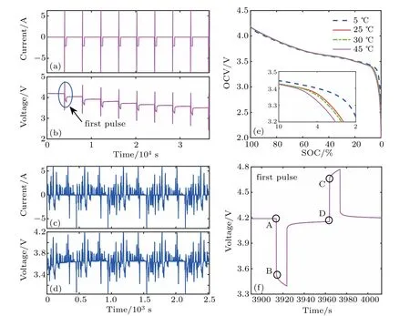
Fig.2.Plots of(a)input current and(b)voltage versus time of HPPC condition at 25 ∘C,(c)input current and(d)voltage versus time of US06 condition at 25 ∘C,(e)the OCV–SOC at 5 ∘C,25 ∘C,30 ∘C,and 45 ∘C,and(f)the local enlarged voltage versus time of the first pulse in panel(b).
3.Battery modeling and parameter identification
3.1.Enhanced battery model
The common 2RC-ECM is widely used in LIBs modeling and SOC estimation due to these merits like higher calculation efficiency,easy implementation in engineering,and better simulation of battery dynamics behaviors.[1–3,18,29]As can be seen from Fig.2(e),the variations of the OCV–SOC trajectories at different ambient temperatures almost coincide with each other in the 10%-to-100%SOC range,whereas there exists significant difference in the low SOC range less than 10%.In other words,under different ambient temperatures(denoted by symbol T),the same OCV may correspond to different values of battery SOC,especially when SOC is less than 10%.Additionally,we can conclude that the ambient temperature has great influence on the battery electrical dynamics behavior,and the SOC estimation is highly dependent on the accurate modeling of LIB.Therefore,it is necessary to derive an enhanced lithium–ion battery equivalent circuit model considering the influence of ambient temperatures,which is shown in Fig.3.

Fig.3. Enhanced second-order resistor–capacitor equivalent circuit model.
Unlike the common 2RC-ECM of LIB cell,Rtempis used to describe the change of battery impedance with ambient temperature,and the OCV is considered as a function of battery SOC and ambient temperature,which is denoted by UOC(SOC,T),thus this enhanced battery model is composed of Rtemp,Ohmic internal resistance R0,two parallel RC networks connected in series(i.e.,R1–C1and R2–C2),and the battery TOV denoted as Ut,with the applied current density being It.
Here in this work,according to the Kirchhoff’s laws,we can construct the state-space equations for describing the relationships among capacitor,voltage,and current of this battery,and are described mathematically as follows:

3.2.Parameter identification and validation
3.2.1.EFF-based model parameter identification
In this part,the HPPC test profiles are utilized to perform the parameters identification and the hysteresis phenomenon of battery OCV under charging and discharging profiles are taken into account.For R0,when the battery is discharged at each pulse,the battery TOV will drop instantaneously,denoted by UA–UB,on the contrary,when the battery is charged at each pulse,the battery TOV will jump instantaneously,denoted by UC–UD,see Fig.2(f).Under this situation,the value of R0can be acquired from the following equations:[30–33]


where R0,Discand R0,Charefer to the values of R0at the discharge and charge conditions,respectively.
According to Eq.(1),the battery TOV in the relaxation period(zero-input response period)can be expressed as

where τ1=R1C1and τ2=R2C2.
Moreover,according to Eq.(4),the other parameters,i.e.,R1,C1,R2,C2,and Rtempcan be obtained by the EFF method.And the battery TOV during the relaxation period can be fitted to the exponential function form expressed as

where m0,m1,m2,λ1,and λ2are the coefficients to be determined,which can be obtained by the EFF method.
By comparing the corresponding coefficients between Eq.(4)and Eq.(5),the values of R1,C1,R2,C2,and Rtempcan be acquired as follows:

Table 2.Identified parameters of LIB cell under charge profile.
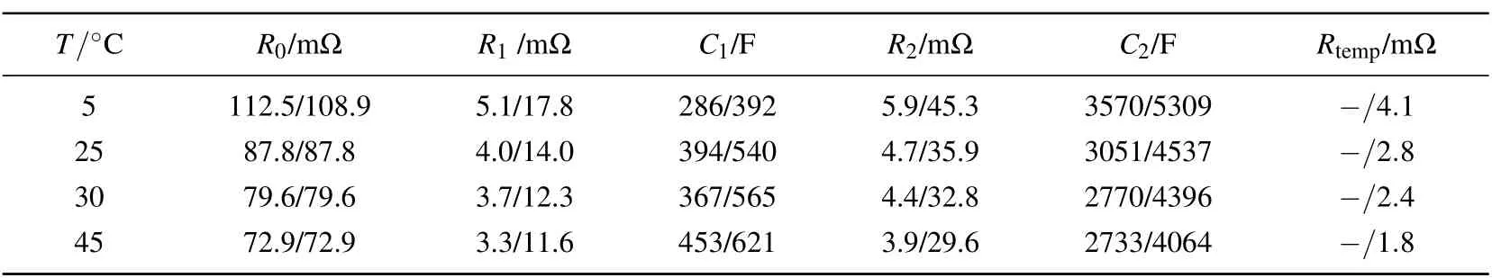
Table 3.Identified parameters of LIB cell under discharge profile.
According to the above-mentioned procedure,we can further obtain the identified parameters under charging and discharging as listed in Tables 2 and 3,respectively,in which,the corresponding values of Rtempare obtained only by using the proposed battery ECM at 5∘C,25∘C,30∘C,and 45∘C,separately.It is worth noting that the parameter identification is performed for the enhanced battery ECM and the common 2RC-ECM by using those nine pulses discharge and charge profiles with the help of EFF method,and the finally obtained parameters are the averaged values of the identified parameters under each pulse profile.On the one hand,according to the related parameters listed in Tables 2 and 3,we can obtain the plots of Fig.4 to reveal the identified parameters varying with SOC values under the discharge/charge conditions at 25∘C,respectively.It can be concluded from Fig.4 that both R0and Rtempdecrease with SOC increasing;the variations of R1and C1have greater fluctuations in the lower SOC range of(0%–30%)and have a smooth tendency in the other SOC range(30%–100%);moreover,the variations of R2and C2have a decreasing tendency with SOC increasing on the whole.

Fig.4.Variations of obtained parameters with SOC value under charge and discharge conditions at 25 ∘C.
On the other hand,to further reveal the variations of the final identified parameters with ambient temperature,the curves of R0,Rtemp,R1,C1,R2,and C2versus T are fitted by using the cubic polynomials under discharge and charge conditions as shown in Fig.5,which is useful for improving the adaptability of this enhanced battery model.
Note that the left and right values in each row for Tables 2 and 3 refer to the identified parameters for 2RC-ECM and proposed battery model,respectively.
It is noted that the blue asterisk(*)and magenta circle(○)denote the identified parameter values in Tables 2 and 3 from the proposed battery model;and the blue and purple solid lines denote the fitted function relationships of each parameters with regarding to T in terms of the identified parameters under charge and discharge conditions.For example,the function of Rtemp(T)in Fig.5 can be used to estimate Rtempat any arbitrary ambient temperature,thus improving the practicability of the enhanced battery model.
Additionally,it is observed from Fig.5 that the variations of R0and Rtempboth have an obvious decreasing tendency with T increasing;the variation of R1has a slower decreasing tendency,and its corresponding capacitor C1increases significantly with T increasing;moreover,the variation of R2and C2are both significantly increased with T increasing.
3.2.2.Model validation and evaluation
To verify the accuracy of the identified parameters,the measured and estimated battery TOV from the 2RC-ECM and this enhanced model under HPPC and US06 profiles at 25∘C are shown in Figs.6(a)and 7(a),respectively,and the corresponding TOV errors are also shown in Figs.6(b)and 7(b),respectively.
It can be observed that the enhanced battery model can well predict the battery TOV,especially from Figs.6(b)and 7(b),and that the TOV errors of the proposed battery ECM are obviously less than those of the 2RC-ECM under the same test profiles.It should be noted that the HPPC profiles ranges just from 100%to 10%,i.e.,from higher to lower SOC range,and both the battery TOV curves and the TOV errors show that the proposed battery ECM is more accurate than the common 2RC-ECM in predicting battery TOV.

Fig.5.Variations of obtained parameters versus T from curve fitting method under charge and discharge conditions.

Fig.6.(a)Battery voltage and(b)voltage error varying with time under HPPC test profile at 25 ∘C.
Note that the left and right values in each row of Tables 4 and 5 represent the MAE and RMSE for 2RC-ECM and the enhanced battery model,respectively.

Fig.7.(a)Battery voltage and(b)voltage error varying with time under US06 test profile at 25 ∘C.
Moreover,in order to obtain the accuracy of SOC estimation for the enhanced battery ECM and the common 2RCECM,in Tables 4 and 5 listed are the comparisons between MAE and RMSE for battery TOV under HPPC and US06 profiles at 25∘C,respectively.It is seen from Tables 4 and 5 that no matter the test is carried out under HPPC or US06 test profiles,the values of MAE and RSME for the enhanced battery model are less than those of the 2RC-ECM under the same operation at the arbitrary ambient temperatures,which indicates that our enhanced battery model has higher estimation accuracy.
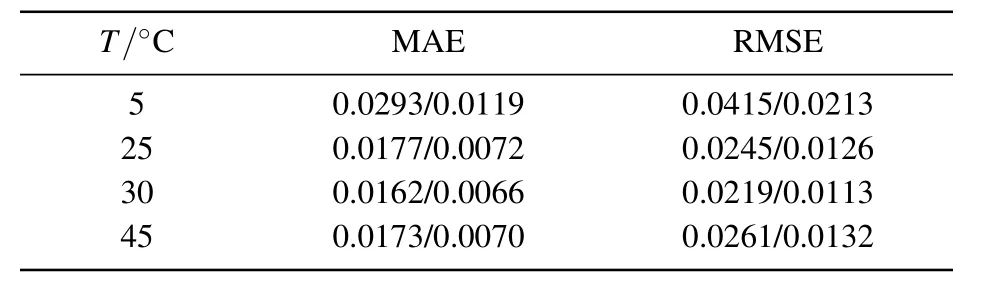
Table 4.Comparisons between MAE and RMSE under HPPC profile at 25 ∘C.
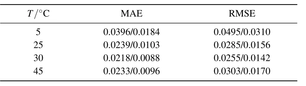
Table 5.Comparisons between MAE and RMSE under US06 at 25 ∘C.
4.SOC estimation based on EKF algorithm
4.1.EKF-based on SOC estimation algorithm
Due to its merits of providing higher accuracy and lower calculation cost,the EKF algorithm has been widely used to perform the parameter identification and SOC estimation in BMS.[34,35]It should be noted that the key point of the EKF algorithm is to minimize the error between the measured result and the simulated model output through a Kalman gain for a nonlinear Gaussian noise system with recursive algorithm.In order to apply EKF algorithm to the SOC estimation of the enhanced battery model,we need to present a general framework for the discrete-time state and measurement dynamic equations as follows:


First,for the enhanced battery model shown in Fig.3,the discrete form of Eq.(1)is obtained as

where Tsis the sampling interval.
Next,define the system state,the measured valueand the input matrixas

where SOCkis the observation of SOC in time step k,which is given by

Note that Ccapis the nominal capacity shown in Table 1,η represents the Coulomb efficiency that is assumed to be 1 and 0.98 at charging and discharging stages,respectively,and It,kindicates the applied current.
Finally,the discrete-time state-space equations of the enhanced battery model are depicted as


where α is the slope of OCV–SOC curve at ambient temperature,and it is usually calculated by virtue of the local linear interpolation method based on the OCV–SOC relationship shown in Fig.2(e).
To facilitate the understanding of the EKF-based SOC estimation procedure,we present the implementation flowchart of the EKF-based SOC estimation approach used in this enhanced battery model,which is shown in Fig.8. It should be noted that the input is the test profiles of LIB at different ambient temperatures,and then the EKF algorithm provides a Kalman gain to update the state estimate measurement

Fig.8.Implementation flowchart of EKF-based SOC estimation.
4.2.Results and discussion
In this subsection,to reveal the advantages of this enhanced battery model with respect to the SOC estimation,the values of SOC are estimated from the 2RC-ECM and the enhanced battery model by incorporating the EKF approach,which is denoted as SOCest,i. Meanwhile the experimental SOC is obtained by the Coulomb counting(ampere-hour counting)based on the measured test data in Section 2,which is denoted as SOCexp.The relative SOC error is defined as

where i=1 is for the battery 2RC-ECM and i=2 for the enhanced battery model.
Figures 9 and 10 show the comparisons between battery SOC and SOC errors with the 2RC-ECM and the enhanced model under HPPC and US06 test profiles at 5∘C,25∘C,and 45∘C,respectively. Figures 9 and 10 show apparently that the battery SOC estimation with the enhanced model can well track the SOCexpin the entire test profiles. Moreover,it is clear that the SOC errors with the enhanced model are overall less than those of the common 2RC-ECM without considering the influence of ambient temperature,and the SOC estimation errors are maintained in the ranges of 0%–2.10%,−1.43%–0.15%,and 0.38%–3.12%for the enhanced battery model,at each ambient temperature under the HPPC condition.In the US06 profiles,the SOC estimation errors are maintained in the ranges of −0.38%–0.11%,−0.87%–0.04%,and 0.08%–0.13%for the enhanced battery model at each ambient temperature.Besides,it is obvious that the SOC error of the enhanced battery model yields comparatively minor fluctuations in comparison with that of the battery 2RC-ECM,which further implies that our enhanced battery model with the identified parameters has higher accuracy in estimating battery SOC under HPPC or US06 test profile.
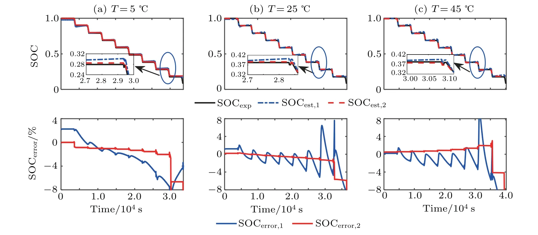
Fig.9.Comparisons between SOC and SOC error based on two different models by using OCV–SOC curve at(a)5 ∘C,(b)25 ∘C,and(c)45 ∘C under HPPC test profile.

Fig.10.Comparisons between SOC and SOC error based on two different models by using OCV–SOC curve at(a)5 ∘C,(b)25 ∘C,and(c)45 ∘C under US06 test profile.
5.Conclusions
As is well known,the ambient temperature usually exerts a significant influence on the model parameters and SOC estimation for lithium–ion battery.In this paper,an enhanced battery model is proposed with considering the influence of ambient temperature on the battery OCV.A temperature-sensitive resistor is introduced to describe the influence of ambient temperature on the change of battery impedance.Besides,the EEF method is adopted to identify the offline battery internal states,and a cubic polynomial function is utilized to fit the highly nonlinear relationship between the identified parameters set(R0,Rtemp,R1,C1,R2,and C2)and T. An SOC estimation based on EKF algorithm is then conducted by using the measured HPPC and US06 test profiles. The experimental and simulated results show that this enhanced battery model can well predict the variations of battery SOC with a maximum error less than 2.0%and 0.25%,respectively,which illustrates that our enhanced battery model can simultaneously improve the battery SOC estimation accuracy,compared with the general 2RC-ECM for lithium–ion battery.Future work will focus on finding a comprehensive description of the battery dynamic behavior and achieving the precise and stable SOC estimation.

- Chinese Physics B的其它文章
- Compact finite difference schemes for the backward fractional Feynman–Kac equation with fractional substantial derivative*
- Exact solutions of a(2+1)-dimensional extended shallow water wave equation∗
- Lump-type solutions of a generalized Kadomtsev–Petviashvili equation in(3+1)-dimensions∗
- Time evolution of angular momentum coherent state derived by virtue of entangled state representation and a new binomial theorem∗
- Boundary states for entanglement robustness under dephasing and bit flip channels*
- Manipulating transition of a two-component Bose–Einstein condensate with a weak δ-shaped laser∗