
Multi-objective strategy to optimize dithering technique for high-quality three-dimensional shape measurement∗
2019-11-06 00:44NingCai蔡宁ZheBoChen陈浙泊XiangQunCao曹向群andBinLin林斌
Chinese Physics B 2019年10期
Ning Cai(蔡宁),Zhe-Bo Chen(陈浙泊),Xiang-Qun Cao(曹向群),and Bin Lin(林斌),†
1State Key Laboratory of Modern Optical Instrumentation,CNERC for Optical Instruments,Zhejiang University,Hangzhou 310027,China
2Research Institute of Zhejiang University-Taizhou,Taizhou 318000,China
Keywords:three-dimensional(3D)shape measurement,multi-objective,dithering,genetic algorithm
1.Introduction
Digital fringe projection(DFP)techniques become multiply crucial due to their measurement accuracy and flexibility.Actually,it remains difficult to obtain high accuracy and high speed simultaneously.[1–3]The conventional DFP technique uses 8-bit sinusoidal fringes. which limits the measurement speed to the projector refresh rate(typically 120 Hz).[4]In addition,measurement error is introduced,if a commercial projector is utilized without calibrating its nonlinear gamma.[5]
The binary defocusing techniques have been developed to break the speed bottleneck.[1,6,7]Moreover,nonlinear gamma can be eliminated automatically with 1-bit depth patterns.However,some additional issues are present and need handling:(i)the smaller depth range and(ii)the high-order harmonic error.To address the aforementioned issues,endeavors have been made.Su et al.[8]introduced a three-dimensional(3D)measurement system by utilizing the defocused projection of a Ronchi grating at the very beginning. Later,Lei and Zhang[9]introduced squared binary defocusing method(SBM),then Ayubi et al.[10]presented sinusoidal pulse width modulation(SPWM)technique,and Wang and Zhang[11]presented optimal pulse width modulation(OPWM)technique.The SBM technique can achieve good performance only when a projector is properly defocused.Both SPWM and OPWM technique can generate good results even with a nearly focused projector.However,SBM,SPWM,and OPWM all fail to produce a high-performance 3D measurement with a long fringe period.Since the techniques described above only modulate the patterns in one dimension,it is natural to utilize twodimensional(2D)area modulation methods to enhance the measurement quality for wide fringe stripes.
To address challenges for wide fringe stripes,dithering,[12]also called halftoning,technique is introduced.It can significantly enhance the phase quality with wide fringe stripes,but suffer limitation when fringes are narrow.[13]Actually,dithering technique is only a simple matrix transformation therefore far from being optimal. Various methods of dithering optimization are developed for DFP systems.A phase-optimized framework was proposed to optimize the Bayer-dithering technique by Dai and Zhang.[14]And then,an intensity-optimized dithering technique[15]was also introduced.Compared with intensity-optimized technique,the phase-optimized technique can achieve better 3D shape measurement results,but it is more sensitive to defocusing amount.
Genetic algorithm(GA)[16]was first introduced by Holland and his colleagues.The GA is a non-deterministic global optimization fitting for binary fringe generation,which obtains an optimal solution through selection,crossover,and mutation stages.Lohry and Zhang[17]introduced a genetic method to optimize dithering techniques,but the time-consuming problem remained to be solved.
In this paper,we present a multi-objective optimization framework,which includes both an intensity-based objective and a phase-based objective.It effectively balances the measurement quality and sensitivity to the defocusing amount.In addition,to solve the time-consuming issue of GA,our framework abandons any attempt to optimize the whole pattern pixel by pixel. According to the property of a sinusoidal pattern,the binary pattern should be symmetric and periodical. We search a best binary patch and tile the patches together so as to present a whole pattern utilizing periodicity and symmetry.It is shown that the presented technique can consistently achieve substantial phase quality improvement with various defocusing amounts.
Some related principles of the proposed technique are introduced in Section 2.Simulations and experiments are presented in Sections 3 and 4,respectively.Finally we draw some conclusions from the present study in Section 5.
2.Principle
2.1.Three-step phase shifting
Various phase-shifting algorithms have been developed for phase analysis technique.[18]Typically,these algorithms obtained better 3D measurement results with more fringe patterns.Usually a three-step phase-shifting algorithm is adopted in high-speed metrology,with requiring a minimum number of patterns.Three 2π/3 phase-shifted fringes can be expressed as follows:
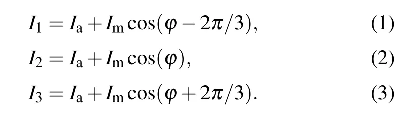
Here,Imrepresents the modulation intensity,Iathe average intensity,and ϕ the unwrapped phase calculated from
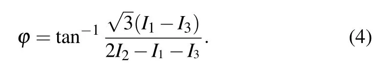
The phase values yielded from Eq.(4)are in a range[−π,+π)and have a 2π jump,which can be eliminated by the phase unwrapping technique.[19]
2.2.Error-diffusion dithering techniques
The dithering techniques used in computer graphics have been developed to represent a color depth with a limited depth.[20]To modulate the binary patterns,various dithering techniques are utilized,such as error-diffusion dithering,pattering dithering,simple thresholding,ordered dithering,and random dithering. The high accuracy of the error-diffusion dithering technique makes it extensively used in the past years.For an error-diffusion algorithm,a diffusion kernel d(i,j)is used to quantize the pixels in a specified order. The unprocessed pixels are compensated for by quantization errors of the pixel being processed.The process can be given as

where symbol ∗denotes the pixel being processed,symbolizing the previously processed pixels.
2.3.Multi-objective optimization
As discussed previously,the intensity-optimized technique tries to eliminate the intensity differences compared with the sinusoidal fringe.That is to say,a Gaussian smoothed binary fringe ought to be as close to a sinusoidal fringe as possible.The intensity-optimized problem can be described as

Here,Eidenotes the intensity error,I the sinusoidal fringe,the Frobenius norm,G the filter using Gaussian kernel,⊗the convolution,and B the desired binary pattern.The phase-optimized technique tries to achieve minimum phase error compared with the Gaussian filtered binary fringe with the sinusoidal fringe. The phase-optimized problem can be described as

where Eprepresents the phase error,Φithe ideal unwrapped phase,and Φbthe binary unwrapped phase.
The optimization we propose is to take a comprehensive account of the intensity domain and the phase domain.Mathematically,the objective of optimization can be described as

where Imis the intensity modulation and α is a weighting coefficient ranging[0,1].
2.4.Genetic optimization framework
To solve the time-consuming issue of GA,a binary patch is optimized,instead of the whole fringe pattern which typically is 1024×768. The optimized patch can then be tiled with respect to symmetry and periodicity so as to generate the whole pattern.Assuming that the sinusoidal fringe is vertical,two phenomena come into notice:i)it ought to be periodic in not only the horizontal direction but also the vertical direction;and ii)it must be symmetric in one period along the horizontal direction.The flowchart of optimization steps is shown in Fig.1 and can be described as follows.
Step 1Individual size determination
The patch size is initialized by the row period Sy(Sy=1),and the column period Sx(Sx=T/2).Here,T is the fringe period.The individual is set to be an array with a length of Sy×Sx.
Step 2Population initialization
The GA considers a collection of individuals called a population.We design a population of 60 patches for each generation.Different patches can be formed with respect to the property that it is path-and origin-dependent for an error-diffusion algorithm.Among the patches,4 patches are respectively extracted from the error-diffusion dither patterns with algorithm starting from the four vertices of the sinusoidal fringe pattern,and the other patches are randomly initialized.
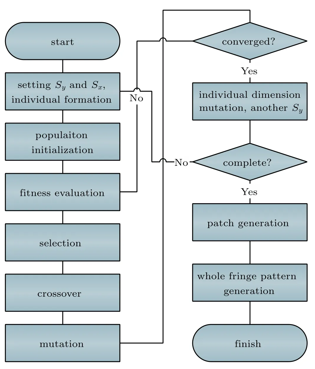
Fig.1.Flowchart of optimization steps.
Step 3Fitness evaluation
Individuals are evaluated by the fitness function described in Eq.(9).
Step 4Selection
Individuals with good characteristics are selected as parents related to probability. The stochastic uniform selection method is adopted in this paper.
Step 5Crossover
Crossover is the most important operator of the GA.A random position and a random length is chosen to speed up the process,the region which has a larger error is more likely to be chosen with a probability that is greater than 50%.
Step 6Mutation
In typical GA implementations,the mutation rate is very small.We set the rate to be 1%,and the region with higher error undergoes mutating more than 50%of the time like crossover.
Step 7Iteration
If the stopping criterion is not satisfied,go back to Step 3.In this paper,the stopping criterion is that the average change of the fitness is less than 10−6,or the iteration is more than 5000 times.
Step 8Individual dimension mutation
Increase Syby 1 and go back to Step 1.The maximum number of Syis 15.
Step 9Patch generation
Select the best individual to produce the optimal patch which minimizes Eq.(9)at a certain value of Sy.
Step 10Whole fringe pattern generation
The optimal binary patch can be tiled with respect to symmetry and periodicity so as to generate the whole pattern.
3.Simulations
Some simulations were conducted to verify the superiority of the presented technique. In these simulations,fringe patterns(resolution 1024×768)with periods T=12,18,...,114,120 were used to ensure the practicability.Various defocusing amounts were simulated by using the Gaussian filters with different sizes S and standard σ,(S=[5,9,13],σ=S/3).We use with values of 5,9,13 to represent the slightly defocused,moderately defocused,and severely defocused projectors,respectively.
In this paper,different optimization techniques are optimized by utilizing the Gaussian filter with a size of 5×5 and a deviation of 5/3. During our simulation,we found that the proposed technique was able to obtain fairly good results,when the weighting coefficient α in Eq.(9)was set to be 0.7.The simulations using Gaussian filters with different sizes are shown in Fig.2.Figure 2(a)shows that the phaseoptimized technique always has better result than intensityoptimized technique,while the proposed technique obtains medium-quality result.However,when the size of Gaussian Filter is increased,the results are changed. It is shown that the quality of the phase-optimized technique deteriorates especially with narrow fringe stripes in Figs.2(b)and 2(c).In contrast,the intensity-optimized technique and the proposed technique both consistently enhance the fringe performance under different sizes of Gaussian filters,while the proposed technique works better.The poor performance of the phaseoptimized technique is due to the fact that its optimal pattern is non-sinusoidal.[15]The larger filter size is adopted,the larger deviation appears.The simulation results demonstrate that the proposed technique possesses good persistent performance under various defocusing amounts,which proves the success of the technique.

Fig.2. Comparison among the intensity-optimized technique,the phase-optimized technique and the proposed technique with Gaussian filters of different sizes:(a)5×5,(b)9×9,(c)13×13.
4.Experiments
Experiments were conducted to evaluate the presented technique by utilizing a 3D measurement system equipped with a Daheng mercury camera(MER-130-30UM)of an 8-mm focal length megapixel lens(Computar M0814-MP2)and a projector(Esonic HD-720P).The projector has a resolution of 1280×720,and the image has a resolution of 1024×768.According to the simulation results,we set α=0.7 for Eq.(9).Figure 3 shows the 3D measurement system. The angle of the beams between the projector and camera is approximately 11.7◦.

Fig.3.3D measurement system.
The simulations were experimentally verified with a flat white board.The phase RMS error is shown in Fig.4,as the projector is defocused to a variety of amounts. The phase error was calculated from the difference between the ideal phase and the phase recovered from the binary fringes.The ideal phase was obtained from the measurement results of sinusoidal fringes with 18-step phase-shifting algorithm. Figure 4(a)shows that the phase-optimized technique offers the best result with the slightly defocused projector,the proposed technique is better and the intensity-optimized technique is worst.Figures 4(b)and 4(c)show that the measurement results of the phase-optimized technique deteriorate especially with narrow fringe stripes when the projector is increasingly defocused.In contrast,the proposed technique and intensityoptimized technique continue to enhance the measurement performance under large defocusing amounts,while the proposed technique works better.

Fig.4.Comparison among phase-optimized technique,intensity-optimized technique and proposed technique under(a)slightly,(b)moderately,and(c)severely defocused amounts.
To visually compare these different techniques,we consider a more complex statue.The fringe stripe was chosen to be T=18 pixels in this experiment.Figure 5 shows three binary fringe patterns by using the phase-optimized technique,the intensity-optimized technique and the proposed technique,respectively.And figure 6 shows three defocused patterns by utilizing the three techniques.
Figure 7 shows the 3D measurement results. Figures 7(a)–7(c),7(d)–7(f),and 7(g)–7(i)show the 3D results with increasing defocusing amounts by using different techniques.Table 1 shows the phase error acquired from the difference between the ideal phase and the phase achieved from binary patterns. It is found that the phase-optimized technique cannot apparently improve the performance by increasing the defocusing amount,even though its quality of measurement appears slightly better than those of the proposed technique and the intensity-optimized technique as the projector is slightly defocused.In contrast,the intensity-optimized technique and the presented technique both consistently enhance the measurement performance as the projector is increasingly defocused.It is easy to see that the presented technique offers much better measurement result than the other two techniques under large defocusing amounts.

Fig.5.Three binary patterns generated by(a)phase-optimized,(b)intensity-optimized,and(c)proposed technique.

Fig.6.Three defocused patterns obtained by utilizing(a)phase-optimized,(b)intensity-optimized,and(c)proposed technique.
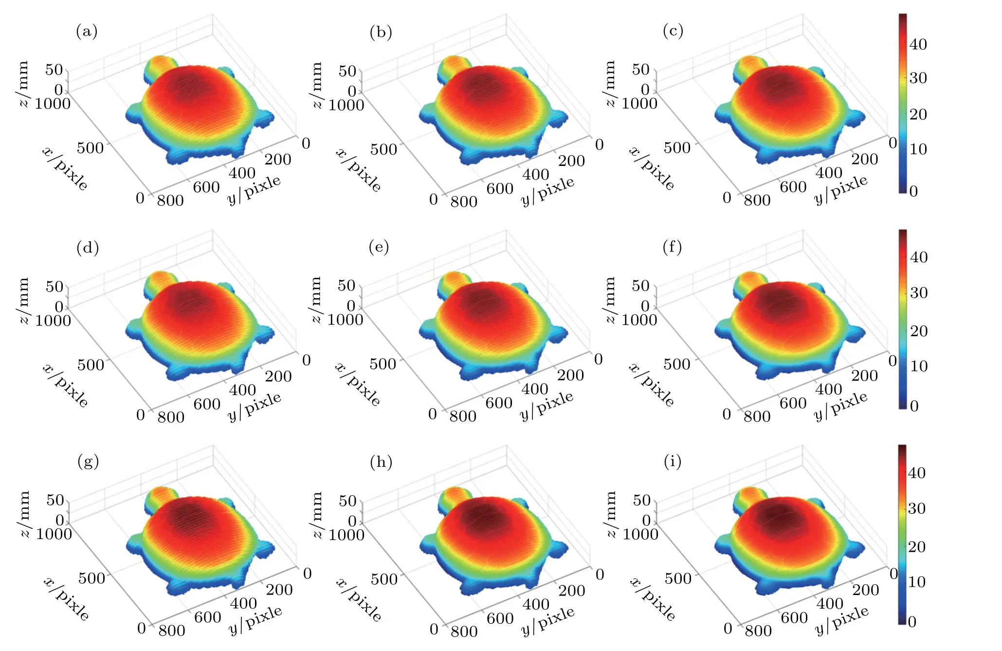
Fig.7.3D results of complex statue,measured by(a)–(c)phase-optimized technique,(d)–(f)intensity-optimized technique,and(g)–(i)proposed technique,when the projector is slightly defocused,moderately defocused and severely defocused respectively.

Table 1.Phase RMS error(in unit rad)of measurement results.
5.Conclusions
In this work, we present a multi-objective optimization framework,which includes intensity-based objective and phase-based objective. It effectively balances the measurement quality and sensitivity to the defocusing amount. It is demonstrated that the proposed technique can significantly improve the measurement performance under various defocusing amounts.

- Chinese Physics B的其它文章
- Compact finite difference schemes for the backward fractional Feynman–Kac equation with fractional substantial derivative*
- Exact solutions of a(2+1)-dimensional extended shallow water wave equation∗
- Lump-type solutions of a generalized Kadomtsev–Petviashvili equation in(3+1)-dimensions∗
- Time evolution of angular momentum coherent state derived by virtue of entangled state representation and a new binomial theorem∗
- Boundary states for entanglement robustness under dephasing and bit flip channels*
- Manipulating transition of a two-component Bose–Einstein condensate with a weak δ-shaped laser∗