
Characterize and optimize the four-wave mixing in dual-interferometer coupled silicon microrings∗
2019-11-06 00:44ChaoWu吴超YingwenLiu刘英文XiaowenGu顾晓文ShichuanXue薛诗川XinxinYu郁鑫鑫YuechanKong孔月婵XiaogangQiang强晓刚JunjieWu吴俊杰ZhihongZhu朱志宏andPingXu徐平
Chinese Physics B 2019年10期
Chao Wu(吴超), Yingwen Liu(刘英文),Xiaowen Gu(顾晓文),Shichuan Xue(薛诗川) Xinxin Yu(郁鑫鑫),Yuechan Kong(孔月婵),Xiaogang Qiang(强晓刚),Junjie Wu(吴俊杰),Zhihong Zhu(朱志宏),and Ping Xu(徐平),3,‡
1Institute for Quantum Information and State Key Laboratory of High Performance Computing,College of Computer,College of Advanced Interdisciplinary Studies,National University of Defense Technology,Changsha 410073,China
2Science and Technology on Monolithic Integrated Circuits and Modules Laboratory,Nanjing Electronic Devices Institute,Nanjing 210016,China
3National Laboratory of Solid State Microstructures and School of Physics,Nanjing University,Nanjing 210093,China
Keywords:silicon resonators,four-wave mixing,Mach–Zehnder interferometer
1.Introduction
Four-wave mixing (FWM), a typical nonlinear optical frequency conversion process,has applications in alloptical processing,[1,2]such as wavelength conversion,[3]phase conjugation,[4]optical parametric amplification,[5]optical sampling,[6]and entangled photon pair generation.[7]The silicon-on-insulator(SOI)offers an appealing platform for four-wave mixing since it is compatible with electronic manufacturing[8]and it also contains a high refractive index contrast[9]and the significant third-order susceptibility.[10]In particular,silicon microrings that limit both transverse and longitudinal optical modes in micron scale and provide resonant enhancement of the nonlinear parametric process,can drastically increase FWM efficiency under a relatively low pump power of several microwatt.[2,3,9,11–15]
To produce the strongest resonant enhancement of FWM efficiency,the microrings’coupling conditions for the four interacting wave play a key role.For the continuous wave(CW)pumped FWM,the microring should be operated at the critical point that is the round-trip loss of the microring equals its power coupling coefficient.[16,17]However,the optimal coupling condition of the pulse pumped FWM should be a different case,because there is a tradeoff between the coupled pump power and the enhancement factor since the higher coupled pump power requires a large resonant linewidth while the overall enhancement factor gets maximized with a narrow resonant linewidth at the critically coupling condition.Thus,an overcoupled condition for the pulse pump is expected while for the converted idler beam the coupling condition may differ since the tradeoff lies in the enhancement factor and extraction efficiency from the ring.However,there are lack of theoretical studies that can formulate the pulse pumped FWM.Experimentally,a single bus waveguide coupled microring resonator or dual-bus microring are usually adopted to perform the FWM process study[18,19]and the efficiency is usually optimized by proper design of the coupling gap between the bus waveguide and the ring.However,these designs can not control the coupling condition of the pump and signal/idler beams independently.
Herein,we derive and formulate the optimal coupling condition for the pulse pumped FWM through the coupledmode equation in frequency domain,which shows the different overcoupling condition of the pump and idler beams should be satisfied for approaching the maximum efficiency.In experiments we design and adopt dual Mach–Zehnder interferometer coupled silicon microrings which allow for the pump and signal/idler beams being operated at specific coupling condition independently.The experimental results agree well with the theoretical predictions.
2.Theory
Assuming undepleted pump and signal when generating the idler,the conversion efficiency of resonance enhanced FWM under CW pump follows the model from Ref.[3]
where the efficiency is defined by the ratio of the on-chip idler power over the signal power,γ is the effective nonlinearity,Ppis the pump power,vgis the microrings’group velocity,Fvis the amplitude enhancement factor with ωvand Ωvbeing the beam’frequency and its resonant frequency,the extrinsic and intrinsic decay rates are defined by rext=vgk/2L and rint=vgα/2 with k and α being the power coupling coefficient and round-trip loss,respectively,L is the circumference of the microring,and Leffis the effective length defined by
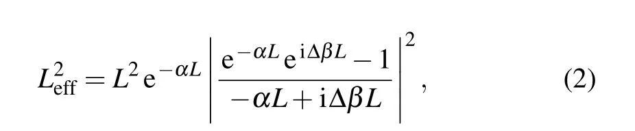
where ∆β is the phase mismatch defined by ∆β=2βp−βs−βi−2γPp.
Assuming the four waves are at resonance and their intrinsic quality factors defined bykeep invariant,the resonant enhancement for the FWM depends on the ratio between the intrinsic quality factor and extrinsic quality factor of the pump,signal,and idler respectively.As shown in Fig.1(a),the FWM efficiency will maximize at the critical coupling point for both the pump and signal/idler beams,namely,where the subscript p or s/i denotes the independent parameter of the pump or signal/idler and the extrinsic quality factor is given by
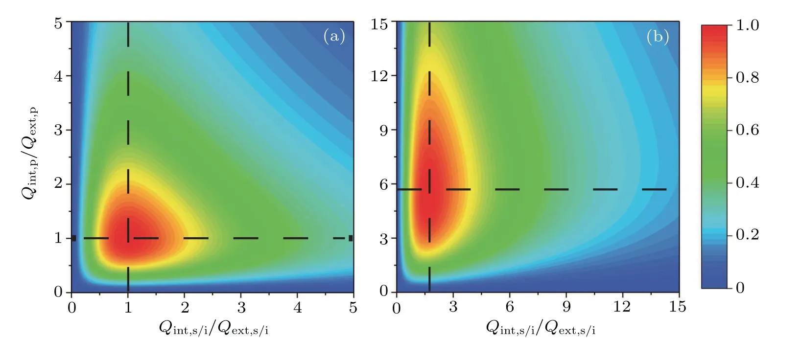
Fig.1.The simulated FWM efficiency versus Qint,p/Qext,p and Qint,s/i/Qext,s/i for both the(a)CW pump and(b)pulse pump.
The conversion efficiency for the pulse pumped FWM can be solved from the coupled-mode equation in the frequency domain
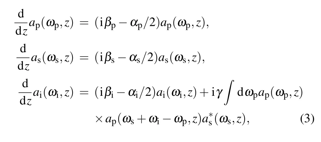
where ap,as,and airepresent the pump,signal,and idler amplitudes in the cavity.Assuming the pump pulse has a Gaussian linewidth and the signal is a CW which is set to be on resonance,equation(3)could be solved as
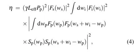
where
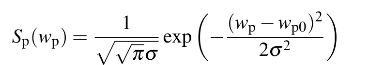
is the pump line type,and σ is related to the frequency bandwidth as
Just like the derivation of CW pumped FWM,we assume that the intrinsic quality factors of four interacting beams keep identical and the idler total quality factors are the same as the signal’s.Then,we calculate the conversion efficiency for the pulse pumped FWM with the pulse bandwidth at 0.17 nm,which is our pulse pump laser’s linewidth,as shown in Fig.1(b). Obviously,to obtain the maximum FWM efficiency,the pulse pump should be operated at the very overcoupling regime with Qint,p/Qext,p≈5.25;meanwhile,the converted idler beam should also be operated at the overcoupling regime but with a different condition of Qint,i/Qext,i≈1.75.So the optimal overcoupling points for the pump and idler beams are different. A specific novel design which can control the pump and idler’s coupling condition independently is highly desired.

Fig.2.(a)Schematic of the dual-interferometer coupled microring.(b)The transmission spectra of the dual-interferometer coupled microring for the in-through side and add-drop side.
Herein,we design a dual-interferometer coupled silicon microring as shown schematically in Fig.2. In 1995,a single interferometer coupled microring was proposed by Barbarossa et al.to suppress certain resonant mode.[20]Later on,several works have adopted such design for both classical and quantum applications.[21–25]Although the dual-interferometer coupled microrings have four ports like the dual-bus microrings,the difference is that each coupled waveguide forms an interferometer with the microring. Thus,the final operation condition of the ring is determined by the effective coupling coefficient given by the interferometer. If the two arms of the interferometer have a length difference ∆L and equals half of the circumference of the microring,the period of interference spectra for the interferometer is twice of the free spectral range(FSR)of the cavity,which allows for every second resonance of the ring to be suppressed by tuning the interferometer’s phase.The transmission spectra of both in-through and add-drop sides are shown in Fig.2,which demonstrates that the resonance allowed by the in-through side will be suppressed by the add-drop side and the resonance allowed by the add-drop side will be suppressed by the in-through side.Then by coupling pump and the signal/idler from different sides,the coupling condition of the pump and signal/idler can be engineered separately. Assuming the two coupling points of the interferometer have the same gap,the effective coupling efficiency of the in-through side(side 1)or add-drop side(side 2)is only decided by this single power point coupling coefficient k1or k2associated with the gap g1or g2. In Fig.2,there are two different transmission spectra for the pump and idler beams under different power point coupling coefficient,respectively.
3.Experiment
A series of 12 dual-interferometer coupled silicon microrings were cascaded and fabricated on a single SOI chip,as shown in Fig.3.Each resonator has a radius of 28µm with the cross-section width and height at 500 nm and 220 nm,respectively. The coupling interferometer has the same radius with the ring and characterized by the single coupling gap which is 180 nm,210 nm,240 nm for the in-through side and 120 nm,150 nm,180 nm,210 nm,240 nm for the add-drop side. Totally 12 combinations listed in Table 1 were fabricated. Thermo-optic modulators were integrated on the microring and long arms of the interferometers to tune the resonance and interferometer phase separately,which ensured that only one of the resonator series was at resonance when measuring FWM efficiency.The silicon grating array was fabricated on the chip for coupling in and out the beams through the off-chip fiber array(FA),with a total coupling loss of 7.13 dB.The linear propagation loss was measured to be 4.23 dB/cm.
Table 1 summarizes the key parameters of the cascaded resonators including the gap combination and quality factors. The quality factors for wavelengths of 1551.0 nm and 1544.6 nm are obtained from the in-through transmission spectra. Meanwhile,the quality factors of resonant wavelengths at 1552.4 nm and 1547.8 nm are obtained from the add-drop transmission spectra.The quality factors are calculated from the scanned transmission spectra using the formula
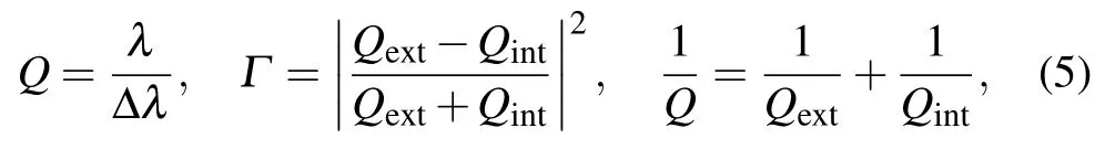
where λ is the resonant wavelength,∆λ and Γ denote the full width at half-maximum(FWHM)and the extinction ratio of the resonance,respectively.
The experimental setup is sketched in Fig.3. The CW laser(Agilent 8164B with a tuning range of 1454–1641 nm and a linewidth of 50 MHz)or the pulse laser(PriTel Inc.FFLTW-60 MHz with a wavelength bandwidth of 0.17 nm)serves as the pump beam and another CW laser(Yenista Tunics T100s with a tuning range of 1500–1630 nm and a linewidth of 0.4 MHz)is used as the signal beam.The pump and the signal beam polarizations are controlled by two separate polarization controllers before they could reach the chip.The idler alongside the residual signal from the drop port are separated and filtered by a dense wavelength division multiplexer(DWDM).The resonance of the pump and signal is monitored by two power meters(PM).The average power of the converted idler is recorded by another PM.

Fig.3.Experimental setup and the photograph of our dual-interferometer coupled silicon microrings.PC,polarization controller;DWDM,dense wavelength division multiplexer;FA,fiber array;PM,power meter.

Table 1.Key parameters of the 12 dual-interferometer coupled silicon microrings and the raw FWM efficiency alongside the loss-subtracted efficiency,Q,Qext(×104).The column with the subscript ls represents the loss-subtracted conversion efficiency;CE,the conversion efficiency.The column with pulse1 or pulse 2 represents the pump coupled through the in or drop port,respectively.
For the CW pump FWM experiment,the pump photons with wavelength at 1551.0 nm are input through the in port and the signal photons with wavelength at 1554.2 nm are input though the add port.The raw measured conversion efficiency for the CW pump FWM using the pump power of 268µW and the signal power of 118µW is listed in the sixth column of Table 1.It is unfair to directly compare the FWM efficiency of different resonators,since the on-chip propagation loss is not negligible and the optical path lengths of the pump,signal,and idler beams for the 12 cascaded resonators also differ from each other.By deducting the impact from the on-chip propagation loss,we give the loss-subtracted conversion efficiency,as listed in the seventh column of Table 1.The maximum efficiency of −44.8 dB is achieved in the resonator with the gap combination of 240 nm of both interferometers. It is worth noted that here the pump power is set to be low so that no obvious two-photon absorption and free-carrier absorption are involved in this four-wave mixing.
By substituting the quality factor in Table 1 to Eq.(1),we calculate the theoretical conversion efficiency,which agrees well with experimental results as shown in Fig.4(a). In order to analyze the optimal coupling condition for both the pump and signal,we focus on the key parameters of the ratio between the intrinsic and extrinsic quality factors,that is Qint,p/Qext,pand Qint,i/Qext,i. Deducting the contributions from the signal and idler’s enhancement factor and the pump’s intrinsic factor,the conversion efficiency scale withis in the following formwhere A is a constant for each resonator. Figure 4 shows the theoretical curve and experimental results,which demonstrates that when the pump beam approaches the critical coupling point,the FWM efficiency becomes higher. For comparing the conversion efficiency of the 12 dual-interferometer coupled silicon microrings with different idler coupling conditions,we deduct the contributions from the signal and pump’s enhancement factor and the idler’s intrinsic factor.The efficiency versusis given bywhere B is a constant for each resonator. Both theoretical and experimental results are shown in Fig.4,verifying that the idler should also be operated at the critical point for the maximum CW pump FWM efficiency.
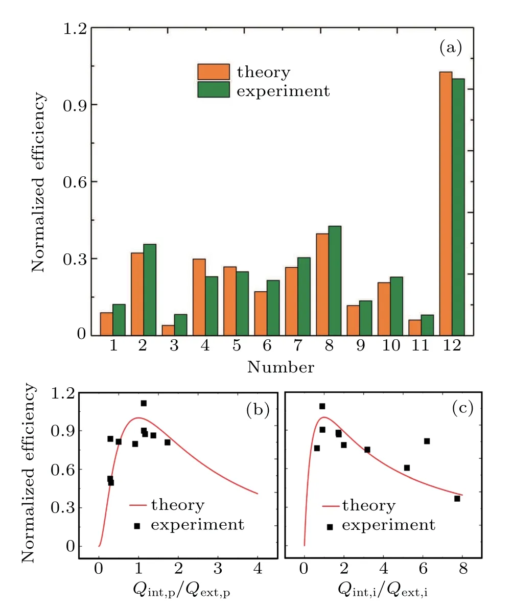
Fig.4. The CW pump FWM experiment. (a)The normalized conversion efficiency of both the experiment and calculation for the 12 resonators. (b)and(c)The normalized conversion efficiency versusand respectively.
Then we substitute the CW pump laser by a pulse laser for the pulse pumped FWM experiment,as shown in Fig.3,while the seeding signal keeps unchanged.The average power of the pulse pumped is 60µW and the signal power is the same as that in the former experiment. Both the in-through side and add-drop side can be used to couple the pulse pump,thus as shown in Table 1 and Fig.5,each resonator has two FWM efficiencies obtained by coupling the pump through the in and add ports,respectively. The measured results consist with the calculated well,verifying that our deduced theory of pulse pumped FWM is effective and solid.For most resonators of the ensemble,the FWM efficiency using the add port as the pump coupling port is much higher than that using the in port as the coupling port. This is because those resonators have narrow coupling gaps for the add-drop side compared with the in-through side,namely,the resonant mode of the add-drop side is at the more overcoupling regime which is preferable for pulse pumped FWM.
To demonstrate the overcoupling condition for both the pump and signal/idler more directly,we list the key resonator parameters and the corresponding FWM efficiency in Table 2.All of the data in the table are obtained by coupling the pulse pump through the drop port.The above three resonators have the coupling gaps of the in-through side fixed at 180 nm and the add-drop side fixed at 180 nm,150 nm,and 120 nm respectively to ensure that the signal and idler’s quality factors have the minimal difference when analyzing the FWM efficiency dependence on pump’s coupling conditions.As the ratio of Qint,p/Qext,pincrease from 1.31 to 5.55,the conversion efficiency also increases,which demonstrates that more overcoupled condition of the pump should be satisfied for higher FWM efficiency.The below three resonators with the coupling gap of the add-drop side fixed at 150 nm and the in-through side varying from 240 nm to 180 nm ensure that the coupling conditions for the pump are approximately the same.The conversion efficiency also increases when the idler beam varies from the undercoupling to overcoupling points,as listed in Table 2.We believe it is the first time to both theoretically and experimentally verify that the pump and idler should be operated at different overcoupling conditions for achieving the maximum pulse pumped FWM efficiency.
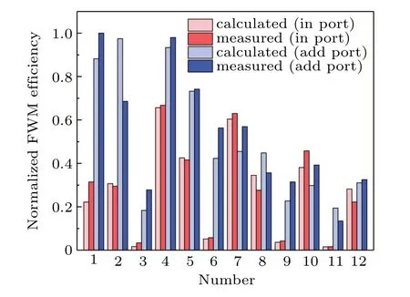
Fig.5.The pulse pumped FWM experimental data.
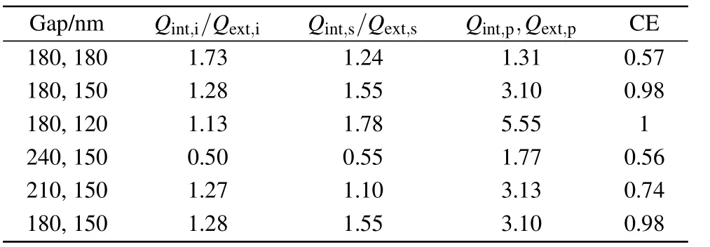
Table 2. Six groups of pulse pumped FWM efficiency by pumping through the drop port with the pump,signal,and idler wavelengths at 1547.8 nm,1544.6 nm,and 1551.0 nm,respectively.CE is the normalized conversion efficiency.
4.Discussion and conclusion
We design and fabricate a series of dual-interferometer coupled silicon microrings for independently controlling the pump and signal/idler’s quality factors. Both the CW and pulse pumped FWM experiments are carried out to verify the optimal coupling conditions for maximizing the FWM efficiency using our design. The critical coupling condition of the pump and signal/idler has been demonstrated for the CW pump FWM in this work.For the first time,we theoretically and experimentally demonstrate that the pulse pumped FWM efficiency can be optimized by independently tuning the pump and signal/idler at their appropriate overcoupling points.Additionally,the dual-interferometer coupled silicon microrings require a low pump power of microwatt scale for efficient FWM and can be integrated with a large density.Thus,it will enable practical use in the research field of on-chip all-optical signal processing.
猜你喜欢
作文小学高年级(2022年3期)2022-04-20
文苑(2020年7期)2020-08-12
海峡姐妹(2019年11期)2019-12-23
作文大王·低年级(2019年2期)2019-01-23
作文大王·低年级(2018年9期)2018-10-24
鄱阳湖学刊(2016年6期)2017-01-16
中国远程教育(2016年6期)2016-12-07
财经(2016年19期)2016-08-11
中国远程教育(2016年5期)2016-06-29
中国远程教育(2016年2期)2016-03-21

- Chinese Physics B的其它文章
- Compact finite difference schemes for the backward fractional Feynman–Kac equation with fractional substantial derivative*
- Exact solutions of a(2+1)-dimensional extended shallow water wave equation∗
- Lump-type solutions of a generalized Kadomtsev–Petviashvili equation in(3+1)-dimensions∗
- Time evolution of angular momentum coherent state derived by virtue of entangled state representation and a new binomial theorem∗
- Boundary states for entanglement robustness under dephasing and bit flip channels*
- Manipulating transition of a two-component Bose–Einstein condensate with a weak δ-shaped laser∗