涡激振动作用下压电悬臂梁俘能器的仿真分析
2020-03-13 20:58王世龙王海峰孙凯利王乐生
青岛大学学报(工程技术版) 2020年1期
王世龙 王海峰 孙凯利 王乐生
摘要: 为了研究涡激振动作用下压电能量收集器与流体域之间的相互作用关系,基于ANSYS仿真软件,建立流-固-压电三场耦合模型,对置于圆柱钝体后一个圆柱直径位置处的压电悬臂梁在风场中的发电情况进行数值仿真分析。仿真结果表明,在卡门涡街的作用下,压电悬臂梁因两侧压力不同而发生振动,压电悬臂梁所发出的电压趋近于正弦信号,最大电压值为20 V。同时,输出电压的相位与压电悬臂梁发生形变的相位一致,与涡街脱落的相位相差180°。该研究证明了仿真计算的可行性,为俘能器的设计提供了理论依据。
关键词: 压电俘能; 压电悬臂梁; 涡激振动; 流固耦合
中图分类号: TN384; TM22 文献标识码: A
收稿日期: 2019-08-27; 修回日期: 2019-12-16
基金项目: 国家自然科学基金资助项目(51405255);山东省高等学校科技计划资助项目(J12LN95);山东省科技发展计划资助项目(2012YD04038)
作者简介: 王世龙(1994-),男,硕士研究生,主要研究方向为计算流体力学分析及压电能量收集。
通信作者: 王海峰,男,博士,副教授,主要研究方向为机电一体化系统设计及计算流体力学分析。Email: 17194456@qq.com
近年来,低功耗电子器件日渐成熟,传统化学电池因体积大,寿命短等因素,无法满足工程需求,利用压电器件收集环境中丰富的振动能量代替传统化学电池为其供能成为可能。空气流场中包含颤振、抖振、驰振、涡激(卡门涡街)振动等[1]四种不同的振动方式,其中涡激振动作为一种常见的风致振动现象,因其引发的振动极具周期性与稳定性,与另外3种振动方式相比更具研究价值。G.W.Taylor等人[2]首先将柔性压电薄膜偏聚氟乙烯(polyvinylidene fluoride,PVDF)固定在圆柱后方,利用水流冲击圆柱产生的卡门涡街,使柔性压电薄膜像鳗鱼一样来回摆动产生电压;H.D.Akaydin等人[3]对一个直径为19.8 mm的钝体后放置的压电装置进行风洞模拟,获得了0.1 mW的输出功率;E.MolinoMineroRe等人[4]对在水中圆柱钝体后放置的压电悬臂梁装置进行验证,在圆柱直径为8 mm时,获得最大功率為0.31 mW;A.Mehmood等人[5]对低雷诺数、高质量比的涡激振动压电能量收集系统进行相关计算,压电装置的输出功率达到10 μW;W.Hobbs等人[6]使用弹性橡胶棒将圆柱钝体与压电片相连,将装置竖直插在地面上,利用圆柱钝体自身的涡激振动带动压电片振动,当风速在1~3 m/s时,输出功率为96 μW。以往研究中,研究者一般通过实验的方法对俘能器的各项参数进行分析与改进[7-15],对卡门涡街与压电片之间的相互作用缺少仿真及理论分析。因此,本文基于ANSYS有限元仿真软件,建立流场-结构-压电三场耦合模型,并进行多物理场耦合分析。分析结果表明,柔性压电片所发出的电压波形接近正弦信号,其主要原因是卡门涡街改变了柔性压电片两侧的压差,从而使压电片产生周期性振动。该研究为俘能器的设计提供了理论基础。
1 压电俘能器系统及理论计算模型
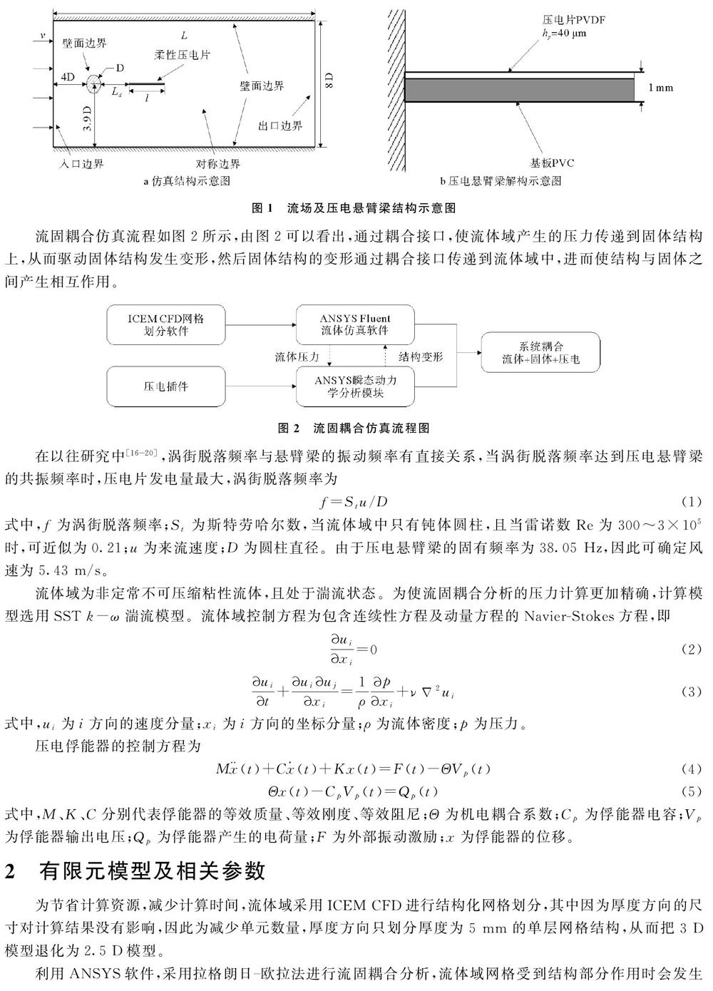
流场及压电悬臂梁结构示意图如图1所示,当风从左侧吹入流场时,因为钝体圆柱的阻挡会在其后方产生卡门涡街,随着涡街的脱落会改变压电片两侧的压力差。其中,计算域上下壁两壁面为无滑动壁面边界,左边为速度入口,右侧为压力出口。钝体圆柱直径为30 mm,压电悬臂梁由聚氯乙烯(polyvinyl chloride,PVC)基板与PVDF柔性压电材料构成,左端固定于圆柱后方30 mm处,右端自由。
流固耦合仿真流程如图2所示,由图2可以看出,通过耦合接口,使流体域产生的压力传递到固体结构上,从而驱动固体结构发生变形,然后固体结构的变形通过耦合接口传递到流体域中,进而使结构与固体之间产生相互作用。
在以往研究中[16-20],涡街脱落频率与悬臂梁的振动频率有直接关系,当涡街脱落频率达到压电悬臂梁的共振频率时,压电片发电量最大,涡街脱落频率为
f=Stu/D(1)
式中,f为涡街脱落频率;St为斯特劳哈尔数,当流体域中只有钝体圆柱,且当雷诺数Re为300~3×10⁵时,可近似为0.21;u为来流速度;D为圆柱直径。由于压电悬臂梁的固有频率为38.05 Hz,因此可确定风速为5.43 m/s。
流体域为非定常不可压缩粘性流体,且处于湍流状态。为使流固耦合分析的压力计算更加精确,计算模型选用SST k-ω湍流模型。流体域控制方程为包含连续性方程及动量方程的NavierStokes方程,即
uixi=0(2)
uit+uiujxi=1ρpxi+νΔ2ui(3)
式中,ui为i方向的速度分量;xi为i方向的坐标分量;ρ为流体密度;p为压力。
压电俘能器的控制方程为
M(t)+C(t)+Kx(t)=F(t)-ΘVp(t)(4)
Θx(t)-CpVp(t)=Qp(t)(5)
式中,M、K、C分别代表俘能器的等效质量、等效刚度、等效阻尼;Θ为机电耦合系数;Cp为俘能器电容;Vp为俘能器输出电压;Qp为俘能器产生的电荷量;F为外部振动激励;x为俘能器的位移。
2 有限元模型及相关参数
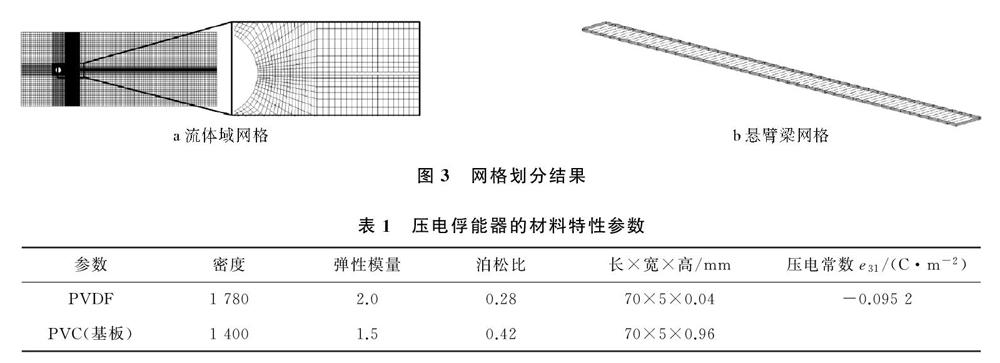
为节省计算资源,减少计算时间,流体域采用ICEM CFD进行结构化网格划分,其中因为厚度方向的尺寸对计算结果没有影响,因此为减少单元数量,厚度方向只划分厚度为5 mm的单层网格结构,从而把3 D模型退化为2.5 D模型。
利用ANSYS软件,采用拉格朗日-欧拉法进行流固耦合分析,流体域网格受到结构部分作用时会发生节点的位移,为防止仿真过程中流体域网格扭曲过大,出现负体积,需要在Fluent软件中开启网格技术。因为采用六面体结构化网格划分方式,所以采用扩散光顺技术使网格变形扩散到固定边界,从而保证变形边界处的网格质量。网格划分结果如图3所示,压电俘能器的材料特性参数如表1所示。
3 仿真分析
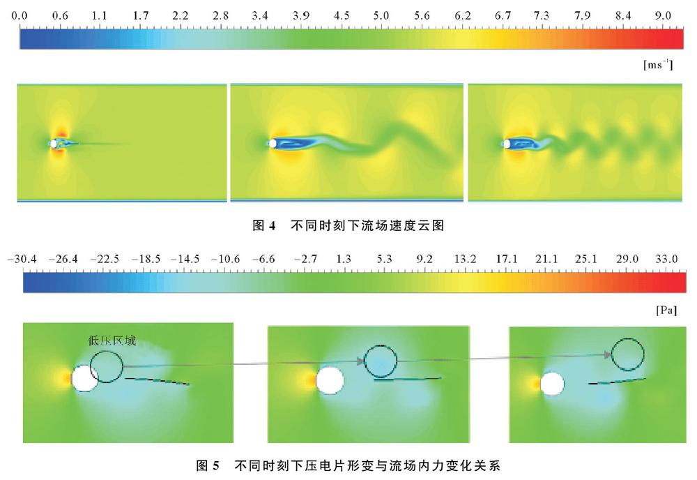
当时间分别为0.01,0.05,0.1 s时,计算流体域中的流场速度,不同时刻下流场速度云图如图4所示。由图4可以看出,流场经过充分发展,钝体后的卡门涡街脱落逐渐达到预定脱落频率,并趋于稳定。不同时刻下压电片形变与流场内力变化关系如图5所示,由图5可以看出,由于卡门涡街的影响,压电片两侧压力不断改变,低压区域从圆柱开始产生,在压电片两侧交替出现,并随时间向右迁移,从而使压电片摆动。
升力系数的周期性变化可以表征涡街周期性脱落。压电片形变、输出电压及圆柱升力系数随时间变化曲线如图6所示。由图6可以看出,压电片输出电压与压电片的末端位移相位一致,与圆柱钝体升力系数相位相差180°,并且压电片的振动响应与涡街脱落相比有一定滞后。
4 结束语
本文主要对涡激振动作用下压电悬臂梁浮能器进行研究,通过流-固-压电三场耦合仿真模型的建立,可以看出涡街脱落可以与柔性悬臂梁发生共振,从而有效激励柔性压电悬臂梁进行振动,并产生足够的有效电压,电压的波形规则且趋近于正弦信号,有利于对俘获的电能进性后续的整流处理。通过仿真云图发现,压电片的振动主要由压电片两侧的压差进行驱动,在此安装状态下,电压的相位与涡街脱落相位相差180°。在仿真过程中,选取的边界条件过于理想化,无法再现海洋环境的复杂工况,仿真结果与实际俘能情况有一定误差,因此需要考虑多种边界条件下的仿真分析。利用ANSYS仿真软件,对系统进行耦合分析,验证了单层流场域建模分析的可行性。该研究为俘能器的设计提供理论依据。
参考文献:
[1] 赵兴强, 王军雷, 蔡骏, 等. 基于风致振动效应的微型风能收集器研究现状[J]. 振動与冲击, 2017, 36(16): 106-112.
[2] Taylor G W, Burns J R, Kammann S A, et al. The energy harvesting EEL: a small subsurface ocean/river power generator[J]. IEEE Journal of Oceanic Engineering, 2001, 26(4): 539-547.
[3] Akaydin H D, Elvin N, Andreopoulos Y. The performance of a selfexcited fluidic energy harvester[J]. Smart Materials & Structures, 2012, 21(2): 025007.
[4] MolinoMineroRe E, CarbonellVentura M, FisacFuentes C, et al. Piezoelectric energy harvesting from induced vortex in water flow[J]. IEEE Instrumentation and Measurement Technology Conference. Graz, Austrial: IEEE, 2012.
[5] Mehmood A, Abdelkefi A, Hajj M R, et al. Piezoelectric energy harvesting from vortexinduced vibrations of circular cylinder[J]. Journal of Sound & Vibration, 2013, 332(19): 4656-4667.
[6] Hobbs W, Hu D. Treeinspired piezoelectric energy harvesting[J]. Journal of Fluids & Structures, 2012, 28(1): 103-114.
[7] Song R J, Shan X B, Lv F C, et al. A study of vortexinduced energy harvesting from water using PZT piezoelectric cantilever with cylindrical extension[J]. Ceramics International, 2015, 41(S1): S768-S773.
[8] Wang H K, Zhai Q, Zhang J S. Numerical study of flowinduced vibration of a flexible plate behind a circular cylinder[J]. Ocean Engineering, 2018, 163: 419-430.
[9] Dai H L, Abdelkefi A, Wang L. Piezoelectric energy harvesting from concurrent vortexinduced vibrations and base excitations[J]. Nonlinear Dynamics, 2014, 77(3): 967-981.
[10] Cheng T, Wang Y, Qin F, et al. Piezoelectric energy harvesting in couplingchamber excited by the vortexinduced pressure[J]. Applied Physics Letters, 2016, 109(7): 073902.
[11] Ewere F, Wang G, Frendi A. Experimental investigation of a bioinspired bluffbody effect on galloping piezoelectric energyharvester performance[J]. AIAA Journal, 2018, 56(3): 1-4.
[12] Kim G W, Kim J, Kim J H. Flexible piezoelectric vibration energy harvester using a trunkshaped beam structure inspired by an electric fish fin[J]. International Journal of Precision Engineering and Manufacturing, 2014, 15(9): 1967-1971.
[13] Castagnetti D. Experimental modal analysis of fractalinspired multifrequency structures for piezoelectric energy converters[J]. Smart Materials and Structures, 2012, 21(9): 094009.
[14] Castagnetti D. A fractalinspired multifrequency piezoelectric energy converter: design and experimental characterization[J]. Advances in Science and Technology, 2012, 83: 69-74.
[15] Franzini G R, Bunzel L O. A numerical investigation on piezoelectric energy harvesting from vortexInduced Vibrations with one and two degrees of freedom[J]. Journal of Fluids and Structures, 2018, 77: 196-212.
[16] Liu W, Xiao Q, Cheng F. A bioinspired study on tidal energy extraction with flexible flapping wings[J]. Bioinspiration & Biomimetics, 2013, 8(3): 036011.
[17] Song R J, Shan X B, Fan M L, et al. Simulations and experiments on a hydrodynamic compound pendulum piezoelectric energy harvester accompanied with vortexinduced vibration[J]. Journal of Vibration and Shock, 2017, 36(19): 78-83, 118.
[18] Li B, You J H, Kim Y J. Low frequency acoustic energy harvesting using PZT piezoelectric plates in straighttube resonator[J]. Smart Materials and Structures, 2013, 22(5): 055013.
[19] Kumar A, Sharma A, Kumar R, et al. Finite element study on acoustic energy harvesting using leadfree piezoelectric ceramics[J]. Journal of Electronic Materials, 2018, 47(2): 1447-1458.
[20] Zhu H J, Gao Y. Vortex induced vibration response and energy harvesting of a marine riser attached by a freetorotate impeller[J]. Energy, 2017, 134: 532-544.
Simulation Analysis of Piezoelectric Cantilever Beam Capacitor under VortexInduced Vibration
WANG Shilong, WANG Haifeng, SUN Kaili, WANG Lesheng
(School of Electromechanic Engineering, Qingdao University, Qingdao 266071, China)
Abstract: In order to study the interaction between the piezoelectric energy harvester and the fluid domain under vortexinduced vibration, a fluidsolidpiezoelectric threefield coupling model is established based on the ANSYS software. The energy harvester of the piezoelectric cantilever beam placed at the position of a cylindrical diameter behind the blunt body of the cylinder is simulated. The results show that under the action of Karman vortex street, the piezoelectric cantilever beam vibrates due to different pressures on both sides. The voltage generated by the piezoelectric cantilever beam approaches the sinusoidal signal, and the maximum voltage value is 20 V. At the same time, the phase of the output voltage is consistent with the phase of the deformation of the piezoelectric cantilever beam, and is 180° out of phase with the vortex shedding. This study verifies the feasibility of simulation calculation and provides a theoretical basis for the design of the energy harvester.
Key words: piezoelectric energy harvesting; piezoelectric cantilever beam; vortexinduced vibration; fluid structure interaction