
Thickening-upward cycles in deep-marine and deep-lacustrine turbidite lobes:examples from the Clare Basin and the Ordos Basin
2020-06-23 02:35LeiFuZhangandDaZhongDong
Journal of Palaeogeography 2020年2期
Lei-Fu Zhangand Da-Zhong Dong
Abstract
Keywords: Thickening-upward cycle, Deep-marine turbidite, Deep-lacustrine turbidite,Yangchang Formation, Ordos Basin, Kilbaha Bay
1 Introduction
Deposits resulting from deep-marine gravity flows can be identified into a“thickening-upward cycle(TUC hereinafter)”pattern in a vertical profile(Mutti and Normark 1987;Macdonald et al. 2011; Grundvag et al. 2014), with an upward transition of shales to interbedded shale-sand to thick massive sandstones.TUC depicts a general vertical trend but does not suggest every overlying bed is thicker than its underlying bed. Since first observed and discussed by Mutti(1974), such thickening-upward cycles have been continuously observed in many deep-marine turbidite successions around the globe.TUC is observed in both outcrops and cores. Widely studied examples include the Pleistocene fans in Kutai Basin (Saller et al. 2008), the Permian Skoorsteenberg Formation in Karoo Basin (Prelat et al. 2009), the Cretaceous fans in Magallanes Basin(Bernhardt et al.2011),the Carboniferous Ross Sandstone Formation in Clare Basin(Macdonald et al.2011;Pyles et al.2014),the Paleogene Wilcox Formation in the Gulf of Mexico (Kane and Ponten 2012),and the Eocene Central Basin of Spitsbergen(Grundvag et al.2014).
Since the 1990s, deep-lacustrine gravity flow deposition has attracted attention from both academia and industry. Gravity flows in the deep-lacustrine environment can lead to deposition of sediments with similar sedimentological characteristics as the deep-marine counterpart (Mulder et al. 2003; Meiburg and Kneller 2010).Depositional elements of deep-lacustrine deposition include slump, channel, levee and lobes (Zhang and Scholz 2015), which are similar to the well-acknowledged deepmarine deposition (e.g. Posamentier and Kolla 2003).Published studies on gravity flows in terrestrial lakes include Malawi Lake (Scholz et al. 1990; Soreghan et al.1999), Reconcavo Lake (Bruhn 1999), Baikal Lake (Nelson et al. 1999), Tahoe Lake (Osleger et al. 2009), Kivu Lake and Albert Depression (Zhang and Scholz 2015).Meanwhile, a tremendous amount of petroleum has been exploited from clastic reservoirs accumulated by deep-lacustrine gravity flows in China. Published examples include Songliao Basin (Feng et al. 2010), Bohai Bay Basin (Zhang 2004; Li et al. 2014), Ordos Basin (Zou et al. 2012) and Junggar Basin (Song et al. 2015). In the Ordos Basin, a single deep-lacustrine gravity flow reservoir in the Triassic Yanchang Formation has an area of more than 3000 km2, with the estimated geological reserve of more than 1×10⁸tons (Zou et al. 2012). In the Songliao Basin, deep-lacustrine turbidite lobes can extend 70 km in length, with an area of more than 2100 km2(Feng et al. 2010), suggesting that despite the much shallower depth than deep-sea, gravity flows in deeplakes can form depositional bodies of similar size.
Although TUC was described in many deep-marine turbidite successions,its origin as to whether it’s an indicator of turbidite deposition remains unknown.Some researchers suggested that TUC was the product of deepmarine turbidite progradation or compensational stacking (e.g. Mattern 2002; Grundvag et al. 2014), while others argued that thickening-upward of individual beds in deep-marine turbidites can be subjectively defined and hence cannot be used as criteria for the identification of submarine-fan environments (e.g. Chen and Hiscott 1999). Furthermore, studies on TUCs in deeplacustrine gravity deposition are scarce, consequently,the complex interplay of sandy debris flows, hyperpycnal flows and turbidity flows in deep-lacustrine environment requires further work (Zou et al. 2012; Li et al. 2016;Shanmugam 2016; Yang et al. 2017). Therefore, the objectives of this study are to (1) explore the occurrence of TUC in deep-marine and deep-lacustrine deposition; (2)compare the TUC formed in deep-marine and deeplacustrine deposition; (3) investigate the origin of TUC in deepwater environment; and, (4) discuss the depositional mechanism of deep-lacustrine gravity flows.
2 Data and methods
The Carboniferous Ross Sandstone Formation in Clare Basin crops out in Kilbaha Bay, western Ireland, has been widely studied and deemed as classic deep-marine turbidite sedimentation outcrops (Pyles 2008). This unit was herein chosen in this study for analyzing the TUC in deep-marine turbidites (Fig. 1). Namurian deposition of the Clare Basin consists of basal deepwater shales (the Clare Shale Formation), followed by turbidite sand-rich submarine fan deposits (the Ross Sandstone Formation),unstable muddy delta-slope deposits (the Gull Island Formation), and fluvial-deltaic shelf margin cyclothems(up to five). The Ross Sandstone Formation is mainly composed of fine-grained sandstones, subordinate laminated shales, and slump/slide deposits of mixed lithology. Turbidite deposits exposed in Kilbaha Bay generally show an east-west strike, where previous researchers demonstrated that the palaeoflow was generally from south to north (e.g. Lien et al. 2003; Pyles 2008). This implies that the continuous outcrops are located perpendicular with respect to the sediment supply direction, which permits a detailed bed-to-bed correlation. Based on 10 sedimentary logs each covering 10-40 m continuous deposits, the bed-to-bed correlation was carefully walked through and examined.
The Triassic Yanchang Formation in Ordos Basin exposed in Shaanxi Province was chosen to study the TUC in deep-lacustrine turbidites (Fig. 2). Deep-lacustrine sandstone facies within the Yanchang Formation were widely reported (e.g. Zou et al. 2012; Li et al. 2015). The Yanchang Formation unconformably covers the underlying Zhifang Formation and is in turn unconformably overlain by the Jurassic Fuxian Formation (Fig. 2). This unit is traditionally divided into ten oil members, ranging from Chang 1 to Chang 10 (Fig. 2c).
The deposition of the Chang 7 oil member is associated with the maximum water level in the lake.In this member,gravity flow deposits comprise thick sandstones and shales(Zou et al. 2012; Fu et al. 2013), which have become important targets for conventional and unconventional oil and gas exploration and development(e.g.tight sandstone and shale; Zou et al. 2012). Nine outcrop logs were measured at three different outcrop localities including Shijiachuan, Yangmahe of Zichang County, Yan’an City,and Yaoqu of Yao County,Tongchuan City(Fig.2b).
3 Results
3.1 Thickening-upward cycles in deep-marine environment

Fig. 1 a Map of Ireland and location of Kilbaha Bay in western Ireland; b Geological map of Kibaha Bay and location of outcrop logs (modified after Pyles 2008);c Satellite map showing the outcrops where outcrop logs were measured
Within the Ross Sandstone Formation exposed at the Kilhaba Bay,thickening-upward cycles can be recognized continuously in a vertical profile (Figs. 3, 4). From bottom to top, a typical thickening-upward cycle (TUC) includes three intervals (Fig. 3a): Interval 1 - Laminated shales/shales with fine-grained siltstone beds (Fig. 3b).Horizontal laminations are generally developed within this interval. Interval 2 - Interbedded thin sandstones/siltstones and mudstones, where climbing ripples/parallel lamination often develop within the sandy part(Fig. 3c). Interval 3 - Structureless massive sandstones(Fig. 3d) with a strong degree of amalgamation (Chapin et al. 1994; Zhang et al. 2017a). Load structures often occur at the base (Fig. 3e). This last interval can be as thick as about 3-4 m comprising a seemingly single thick sandstone bed which is transitioned laterally into several thinner sandstone beds interbedded with shales(de-amalgamation). Overall, such a thickening-upward cycle is 0.5-7.0 m thick and can laterally extend several hundreds of meters to a few kilometers. A unique sedimentary structure occurring within the deep-marine thickening-upward cycles is the “megaflute” (see Lien et al. 2003), which generally occurs at the top of the thick massive sandstone bed but is “repaired” by the basal shales of the next thickening-upward cycle. Megaflutes can erode into the underlying beds more than 2 m.
A thickening-upward cycle is characterized by an upward increase in grain size and therefore it is also called“coarsening-upward cycle”, and by an upward increase in the frequency of appearance of sedimentary structures, such as wavy lamination, parallel lamination, load structures, dish structures and flame structures. Notably,it is characterized by an upward increase of sand/mud ratio and sandstone amalgamation (Zhang et al. 2017a),suggesting a more proximal location with a turbidity flow during deposition, and much higher flow velocity and higher turbulence. Megaflutes implying erosion and flow bypass which are often developed within the upper part of a thickening-upward cycle, occasionally form within the middle Interval 2 with interbedded sandstones and mudstones, and are absent within the basal interval. This also implies the overall increasing flow energy within a thickening-upward cycle.

Fig. 2 a Map of China (modified according to the standard map GS(2016)2923 available on the official website of National Geomatics Center of China)showing the location of Ordos Basin;b Map of Ordos Basin and location of studied outcrops:①Shijiachuan and ②Yangmahe in Zichang County,Yan’an City and ③Yaoqu in Yao County,Tongchuan City;c)Comprehensive stratigraphy column of Ordos Basin(modified after Pan et al.2017).Fm.=Formation
The distribution and mechanism for the formation of thickening-upward cycles and megaflutes in the Ross Sandstone Formation were widely debated. Explanations range from turbidite channel-wing model (Elliott 2000),spill-over lobes at bends of sinuous turbidity channels(Lien et al. 2003), aggrading lobes with scours at channel-lobe transition zones (Chapin et al. 1994; Pyles 2008), to prograding lobe-elements with scours at proximity to channels (MacDonald et al. 2011). In the current study, deposits arranged in thickening-upward cycles are interpreted as turbidite lobes, based on sedimentary structures, laterally extensive sheet-like geometry, repeated presence of thickening-upward cycles and megaflute surfaces in channel-lobe transition zones.Despite different interpretations, thickening-upward cycles have continued to be recognized in the Ross Sandstone (Fig. 4). For the 16.6 m-thick sedimentary Log 9(Fig. 1), 13 thickening-upward cycles are continuously stacked with thickness of each cycle ranging from 1 m to 7 m (Fig. 4). In other nine sedimentary logs, such TUC also stacks in a continuous manner, except when turbidite channel appears with strong erosional surfaces and abundant mud-clasts, which typically displays a vertically thinning-upward pattern.
3.2 Thickening-upward cycles in deep-lacustrine environment

Fig. 3 a A typical thickening-upward cycle (TUC) in the Ross Sandstone Formation, Kilbaha Bay, including: b Interval 1 - Laminated shales/shales with fine-grained siltstone beds; c Interval 2 - Interbedded thin sandstones/siltstones and mudstones; and, d Interval 3 - Structureless massive sandstones with strong degree of amalgamation; e Load structure at base of a thick sandstone bed. White arrow in d shows its location. Note the 0.25 m yellow ruler for scale
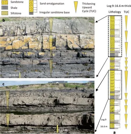
Fig. 4 a Log 9 documenting continuous thickening-upward cycles in the Ross Sandstone Formation, Kilbaha Bay, see Fig. 1 for location of outcrop logs; b and c Outcrop photos showing details of thickening-upward cycles. Successions exposed in c are generally below sea level and covered by seaweed, thus showing different color in b
Gravity flow deposits of the Yanchang Formation exposed in Shijiachuan, Yangmahe, and Yaoqu areas are generally less than 1 km wide due to local topography and vegetation cover. They are not as well exposed as the Ross Sandstone Formation in Kilbaha Bay (>10 km),making detailed bed-to-bed lateral tracing difficult. Typical sedimentary structures within Chang 7 oil member sandstones are mainly flame structures and load casts,flute casts and other sole marks (Fig. 5a), parallel laminae, climbing ripples and horizontal laminae. Bouma sequences and normal grading can be recognized (Fig. 5b).Mud clasts(up to 50 cm in diameter)are developed,especially within the basal part of massive sandstones (“mudcoated intraclast” as in Li et al. 2016), suggesting gravity flow deposition.Within the massive sandstones,amalgamation surfaces are widely developed based on the observation that shale layers with stable thickness pinch out abruptly (Fig. 5c). This particular phenomenon is similar to amalgamations observed in deep-marine turbidites in terms of sizes and shapes, suggesting the layer-by-layer deposition mechanism of such massive sandstones.In fact,such massive sandstones are reported as being stacked and composed of multiple thin sandstones that can reach thickness greater than 10 m and lateral extension larger than several kilometers(e.g.Zou et al.2012),and therefore forming favorable reservoirs.
Thickening-upward cycles are well recognized within gravity flow deposits of the Yanchang Formation at all the three studied outcrops in southeast of Ordos Basin.In Shijiachuan area, a recently opened quarry allows the observation of fresh outcrops of the Yanchang Formation. Four thickening-upward cycles with thickness ranging from 0.5 m to 2.0 m are stacked in a continuous way (Fig. 6a). Sandstones are mainly fine-grained. The thickness of a single massive sandstone bed can reach 3 m.In the 2 m-thick TUC 3 (Fig. 6a), several sandstone amalgamation surfaces can be clearly observed within the massive sandstone at its upper part, implying a strong degree of erosion when the sands were deposited. Meanwhile, all the bases of sandstone beds and shale beds are flat and parallel and can extend laterally for a distance of at least of 800 m without apparent signs of pinch out(based on observation in the quarry),suggesting that these are deep-lacustrine lobes, in contrast to deep-lacustrine channels characterized by irregular bed bases and irregular erosional surfaces. The lateral extension of channels is generally less than 500 m(Feng et al.2010).

Fig.5 Field photographs of sedimentary structures in the Yanchang Formation,Ordos Basin.a Sole marks at the base of a thick sandstone bed at Shijiachuan outcrop; b Bouma sequence at Yangmahe outcrop. Ta: Massive sandstone showing normal grading, Tb: Parallel lamination, Tc: Wavy lamination,Te:Deep-lacustrine shales,Td was absent;c Bed amalgamation within thick sandstones at Yaoqu outcrop
In Yaoqu area, Yao County of Tongchuan City, five thickening-upward cycles are recognized with thickness ranging from 0.9 m to 3.5 m (Fig. 6b). The succession is dominated by yellow-grey fine-grained sandstones and black-grey shales.Deep-lacustrine channel deposits show clear erosional surfaces (red dashed lines in Fig. 6b) that erode into TUC 3. This channel is characterized by an overall thinning-upward pattern, with thick sandstones characterized by irregular erosional surfaces and abundant mud clasts transiting upward into interbedded thin sandstone/siltstones and mudstones.Unlike the other two outcrops of the Yanchang Formation discussed in this study, successions featured by low sand/mud ratio interbedding sandstone/siltstones and mudstones are recognized in this outcrop(overlying TUC 5). Sandstone beds in this outcrop are generally thin (<0.2 m). This outcrop does not display any specific vertical thickening- or thinningupward pattern and is interpreted as overbank deposits or a distal part of deep-lacustrine lobes.Within these five thickening-upward cycles (Fig. 6b),typical gravity flow deposits showing complete Bouma sequences and load structures are recognized,together with abundant sandstone amalgamations.They are interpreted as deep-lacustrine turbidite lobe deposits.
In Yangmahe area, five thickening-upward cycles are recognized with thickness ranging from 0.5 m to 3.5 m(Fig. 6c). Within each TUC, the overall thickeningupward pattern is obvious, amalgamation surfaces are frequently developed. Sandstone beds are 0.3-2.5 m thick with tabular top surfaces and bases.Parallel laminations, wavy laminations are developed within sandstones, and load casts are developed at sandstone bases. Mudstones are relatively thin(0.05-0.20 m), and are disposed parallel with respect to sandstone beds and can maintain their thickness for more than 1 km. Near this outcrop, a deep-lacustrine channel which is inferred to be developed at the top of the upper TUC 5 is also observed, showing entirely different sedimentary characteristics, such as irregular bed bases and ripup mud clasts. This channel is discussed in detail in the following section.
4 Discussion
4.1 Interpretation of deep-lacustrine turbidite lobes
4.1.1 Terminology of turbidity flows and turbidite lobes
Since the 1970s, based on rheology and dominant clastsupport mechanism, sediment gravity flows have been generally classified into turbidity flow, liquified flow,grain flow, debris flow and mud flow (e.g. Middleton and Hampton 1973;Lowe 1982).Notably, turbidity flows are further classified into “high-density turbidity flow”and “low-density turbidity flow”. Their resulting deposits shows vastly different sedimentary characteristics (e.g.Lowe 1982). Meanwhile, other terms such as “subaqueous sediment density flow”are also widely used (e.g. Talling et al. 2012, 2015). Up to the present, few studies have defined specific density values for different gravity flows. An exception is Pratson et al. (2000) who claimed that debris flows typically range in density between 1200 kg/m3and 2000 kg/m3, turbidity flow has a density of 1111 kg/m3assuming a bulk concentration of 5%, and seawater has density of 1030 kg/m3, while “10% of concentration is the maximum a turbidity current can reach” (Pratson et al. 2000). However, to distinguish types of gravity flows based on density may be difficult,since (1) it is difficult to directly measure the flow density during deposition; (2) density is possibly changed by salinity, temperature and pressure of water (Feng 2019).Detailed discussion on defining types of gravity flows is beyond the scope of the current study. Instead, the widely used term “turbidity flow” and resulting “turbidite” are applied throughout this study.
According to the widely cited research of Mutti and Normark (1987), the main characteristics of ancient deep-marine turbidite lobe deposits include tabular, parallel and laterally extensive beds, with specific characteristics such as grading structure and Bouma sequences,resulting in sandstone packages organized into superposed thickening-upward sequences, where many individual sandstone beds are amalgamated.
Deposits of the Yanchang Formation exposed at these three locations are interpreted as deep-lacustrine turbidite lobes, based on (1) typical sedimentary elements (i.e.graded beds, sole marks at bed bases, Bouma sequences)that resulted from turbidity flows; (2) sheet-like geometry inferred from laterally extensive sandstones and mudstones with flat, parallel bases; (3) repeated presence of thickening-upward cycles; (4) frequent amalgamation surfaces within massive sandstones implying a layer-bylayer deposition; and, (5) resemblance with deep-marine turbidite lobes described above and difference with deep-lacustrine channel-fill deposits. Such difference leads to an accumulation of sediment gravity flows (i.e.turbidite lobe and turbidite channel) within a deeplacustrine environment.
4.1.2 Sandstone bed amalgamation
Sandstone amalgamation depicts the phenomenon that overlying sandstone beds are directly in contact with the underlying sandstone beds. The mud-prone barriers are absent, which could have resulted from erosion, pinchout or non-deposition. This phenomenon has been recognized and reported in both fluvial and deepwater environments (e.g. Chapin et al.1994; Mattern 2002; Zhang et al. 2017a). Sandstone bed amalgamations are of sedimentary significance in terms of predicting sedimentary environment and sandstone stacking pattern. Within a single turbulent flow with a lobate-like geometry, the flow energy decreases from the center to the fringe with a radial pattern. This decelerating feature of sedimentladen flow has been discussed earlier and interpreted as“jet flow” (Hoyal et al. 2003) and/or “quasi-steady hyperpycnal flow” (Zavala et al. 2006). Based on the laboratory experiment, Hoyal et al. (2003) identified three zones(Fig. 7), from proximal to distal, characterized by bypass,bed load, and suspension, respectively. Based on detailed outcrop characterization, Zavala et al. (2006) recognized three phases of a hyperpycnal flow, also from proximal to distal, including accelerating phase (AP), erosionplus-bypass phase (EP), and deceleration phase (DP).
Despite different interpretations of flow mechanisms,all these studies suggested that the flow energy, grain size, erosive capacity, and sand/mud ratio decrease downflow (Fig. 7b). Consequently, thick massive sandstones with laterally extensive amalgamations are deposited at more proximal region. Several thin sandstonemudstone interbeds transiting gradually or abruptly into single massive sandstone, form the most obvious amalgamation within deep-marine turbidite lobes. In contrast, more distal flows lead to the deposition of interbedded thin sandstone beds and thick mudstone beds, during which, both sand/mud ratio and degree of amalgamation decrease. Such amalgamations are widely recognized within deep-marine turbidite lobes and deeplacustrine lobes as discussed in the previous section.Within deep-lacustrine lobes where amalgamations occur, the shale layers are abruptly eroded away, yet when examining them laterally, they are generally extensive and have a stable tabular shape, which suggests that they were deposited in a layer-by-layer manner, rather than “freezing” en masse (Zou et al. 2012).
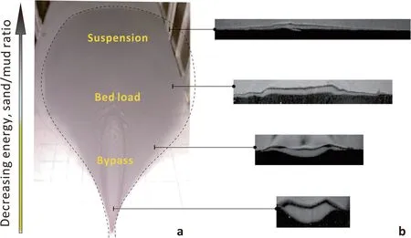
Fig. 7 Simulation diagram of the laboratory experiment conducted by Hoyal et al. (2003). a Deposits showing three zones dominated by processes of bypass,bed load,and suspension; b Across-stream deposit shape,showing less erosional features downflow

Fig. 8 a Examples of deep-lacustrine turbidite channel-fill deposits of the Yanchang Formation in Yangmahe area, Ordos Basin; b-c Close-up views of turbidite channels, generally irregular, with sharp bed bases and abundant erosional surfaces. Rip-up clasts develop in thick sandstones,and no thickening-upward cycle occurs within turbidite channel-fill deposits
Within a thickening-upward cycle, the degree of amalgamation also increases upward in the upper part of a TUC; a high degree of amalgamation occurs, resulting in an amalgamated massive sandstone that can reach a thickness higher than 3 m. No amalgamation occurs in the basal shale-dominated part, whereas the degree of amalgamation in the middle part of a TUC is moderate.Such an upward increase in the degree of amalgamation makes the thickening-upward pattern more obvious. Although no megaflute is observed within deep-lacustrine lobes, the fact that megaflutes only appear in the upper part of a deep-marine thickening-upward cycle also supports the mechanism of prograding.
4.1.3 Deep-lacustrine turbidite channels
Deep-lacustrine turbidite channel-fill deposits are exposed in both Yangmahe and Yaoqu areas. However, because of the inaccessibility to the Yaoqu area, only the turbidite channels exposed in Yangmahe, near the outcrop shown in Fig. 6c, are discussed here. The channel deposits are filled by yellow-grey fine-grained sandstones and grey shales (Fig. 8). Multiple erosional surfaces can be recognized, including small-scale irregular sandstone bases but with little erosion and large-scale erosional surfaces eroding underlying units. Sandstones are 0.1-1.0 m thick with irregular base and abrupt lithological pinch-out, and sedimentary structures such as dish structures, parallel laminations, and wavy laminations are developed. Rip-up mud clasts parallel with beddings are widely distributed, suggesting strong erosion of channelized turbidity flows into underlying mudstones.In a vertical profile, the channel has a concave-upward geometry and a thinning-upward pattern, with a ~0.5 m massive sandstone bed transiting into thin interbedded sandstones/siltstones and draping shales. Laterally, although covered by vegetation, the channel width is inferred to be less than 400 m. The channel deposits in Yangmahe area have some similar characteristics with the turbidite channel deposits reported in deeplacustrine Songliao Basin (e.g. Feng et al. 2010) and deep-lacustrine Bohai Bay Basin (e.g. Chen et al. 2009).However,they differ from those deep-lacustrine turbidite lobe deposits described above, in terms of their dimension, bed geometry, vertical stacking pattern, and, wide distribution of mud clasts.
In summary, the interpretation of deep-lacustrine turbidite lobes in this study is supported by (1) similarities with deep-marine turbidite lobes including typical gravityflow sedimentary structures, sheet-like geometry, amalgamations within massive sandstone beds, and most notably,the repeatedly stacked thickening-upward cycles;and(2)difference from deep-lacustrine turbidite channel-fills.
4.2 Origin of thickening-upward cycles
A thickening-upward cycle depicts a systematic thickening of beds upward on a 1D profile and is recognized both in deep-marine and deep-lacustrine environments.“Compensational stacking” (Mutti and Sonnino 1981),which suggests later deposition tends to “avoid” the highs and “favor” the lows created by older lobes, has been considered to account for the formation of TUC(Mutti and Sonnino 1981). Compensational stacking developed at various scales of lobe deposition, from beds to lobe complexes, has been widely reported (e.g. Mutti and Sonnino 1981;Gervais et al.2006;Deptuck et al.2008;Prelat et al. 2009; Straub and Pyles 2012; Pyles et al. 2014;Zhang et al. 2015). However, compensational stacking might not necessarily lead to ubiquitously repeated thickening-upward cycles. Using statistical analysis, some researchers argued that no consistent vertical pattern exists for turbidites (e.g. Hiscott 1981; Chen and Hiscott 1999).Instead,Macdonald et al.(2011)proposed a continual progradation lobe element deposition model for the Ross Sandstone Formation,to interpret the repeated thickeningupward cycles and the associated “megaflutes” (see Macdonald et al. 2011 for a detailed discussion). Such a lobe element progradation mechanism has been supported and cited by many researchers (e.g. Mutti and Normark 1987;Shanmugam and Moiola 1988; Mattern 2002; Grundvag et al.2014;Pyles et al.2014).This study also favors this interpretation.The degree of amalgamation increases upward along with the increasing grain size and larger bed thickness, suggesting that flow energy increases at-a-point. This can result from a progressively enhanced flow volume and energy,while turbidity flow progrades downward.
At a specific point, when an up-dip turbidity flow was initiated (t1, Fig. 9a), the arrival of the most distal fringes of turbidity flow results in the deposition of laminated shales (Fig. 10e). Distal fringe is mud-dominated due to the limited flow energy which is insufficient to generate erosion and thus accumulate laminated shales with no erosional features nor amalgamations. As the turbidity flow progrades, shales with thin interbedded sandstones/siltstones are deposited, while the sand/mud ratio is still low. With further progradation, the medial part of the turbidity flow (t2, Fig. 9b) characterized by higher sediment concentration and higher flow energy results in the deposition of interbedded sandstones and shales/siltstones, and the sand/mud ratio increases (Fig. 10d).Wavy laminations,parallel laminations are developed,also with local bed amalgamations. The deposition of thick massive sandstones with a high degree of amalgamation implies that the proximal part of turbidity flow(t3,Fig.9c)has the highest sediment concentration and flow energy.

Fig. 9 Schematic model showing the origin of thickening-upward cycles. At a specific point (red lines), from t1, t2, to t3, progradation of multiple flows result in the formation of TUC. Cross-sections depict interbedded sandstone (yellow) and mudstone (grey), showing deposits at a Distal; b Medial;and,c Proximal part.After one TUC forms,avulsion occurs(t4)and another TUC starts to develop
High flow velocity leads to fast amalgamations while fine-grained muds are elutriated. Consequently, finegrained particles within the turbidity flow cannot settle,resulting in deposition of highly amalgamated, thick,massive sandstones with nearly 100% sand fraction(Fig. 10c). At the proximal part, the flow energy is so high that it can erode the underlying soft, muddy substrates, forming typical sedimentary structures such as sole marks. Irregular scours and floating mud clasts are occasionally developed. The highest bypass intensity and erosional energy occur within the channelized turbidity flow, near up-dip feeder channel mouth. Consequently,bypass features like megaflutes and large-scale erosional surfaces are developed (Fig. 10a), with shallow channel typically showing thinning-upward pattern developing at the top of the lobe (Fig. 8a; Fig. 9c). A thickening-upward cycle is therefore formed. Finally, turbidity flow avulsion takes place(t4, Fig.9c), and suspended fine-grained shales are deposited due to sedimentation hiatus. When another turbidity flow is initiated,another thickening-upward cycle will be formed.It is interpreted that this forming mechanism can be applied to explain the origin of both deepmarine and deep-lacustrine turbidites.
Prelat et al. (2009) proposed a hierarchical organization of deep-marine turbidites from beds, to lobe elements, to lobes, and to lobe complexes. The thickening-upward cycle discussed in the current study generally takes place at a lobe element scale. Towards the distal part of a lobe element, beds can be locally disorganized, and the thickening-upward trend may become less apparent at a lobe scale, then a full range of bed thickness stacking patterns (thickening upward, thinning upward and the mixture of both) could occur, perhaps resulted from complex stacking of different lobe elements.
4.3 Implication for deep-lacustrine depositional models
4.3.1 Comparison to deep-marine turbidite model
At least two depositional elements resulted from deeplacustrine gravity flows are recognized: (1) turbidite lobes and (2) turbidite channels. Although slumps are not recognized in the current study, many slumps have been reported within the Yanchang Formation (e.g. Zou et al. 2012). Meanwhile, the classification of depositional elements occurring in the Ross Sandstone Formation is widely agreed by different researchers (e.g. Chapin et al.1994; Elliott 2000; Lien et al. 2003; Pyles 2008), and can be grouped into three main types: laterally extensive sheet-like lobes, shallow channels with associated levees,and fine-grained units including condensed shales, local abandonment shales, slides and slumps. Depositional elements developed within deep-marine and deep-lacustrine environments can be well correlated,suggesting that their depositional mechanisms are similar and comparable.
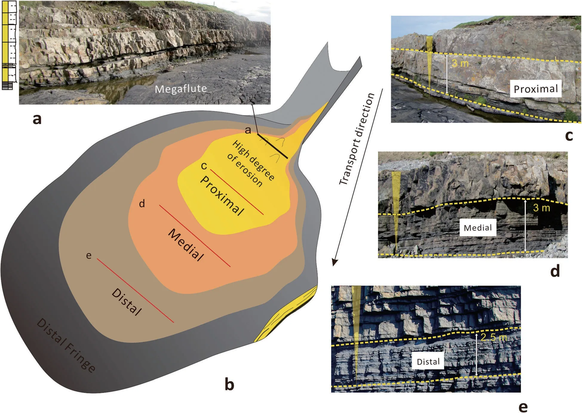
Fig. 10 Schematic depositional model of deepwater turbidite lobe and representative field-photos. a Photos showing a cross-section at channelmouth, megaflutes erode into substrate and are covered by water. A high degree of sandstone amalgamation is inferred since single thick sandstone bed laterally transits into several thinner beds. Dashed lines in the log show amalgamation surfaces; b Schematic depositional model of a deepwater turbidite lobe, along transport direction, with representative photos showing cross-sections at c Proximal; d Medial; and, e Distal part
4.3.2 Comparison to other deep-lacustrine depositional models
To date, the deep-lacustrine turbidite fan model, which is similar to the deep-marine turbidite fan model as proposed by Walker (1978) with channels and lobes, has been widely applied to help petroleum exploration and development in China’s main lacustrine basins, such as:Songliao Basin (e.g. Feng et al. 2010), Bohai Bay Basin(e.g. Zhang 2004; Chen et al. 2009; Li et al. 2014), Junggar Basin (e.g. Song et al. 2015), and Ordos Basin (e.g.Chen et al. 2006; Wang et al. 2006; Liu et al. 2015).However, unlike other Chinese lacustrine basins, arguments still exist on the origin of gravity flow deposition in the Ordos Basin. The gravity flow deposition in the Ordos Basin was interpreted as sandy debrites (e.g. Zou et al. 2012; Fu et al. 2013; Li et al. 2015), turbidites (e.g.Liu et al. 2015), hyperpycnites (e.g. Yang et al. 2015,2017), or a mixture of these.
For the Ordos Basin, many sedimentologists are inclined to the interpretation of sandy debrites, mainly based on the widespread thick structureless massive sandstones with floating mud fabrics (“mud-coated intraclasts”) and an absence of channels (e.g. Zou et al.2012; Li et al. 2016), whereas researchers have not paid equal attention to deep-lacustrine channels within the Yanchang Formation. However, deep-lacustrine channels are developed in the Yanchang Formation, as in the Yangmahe and Yaoqu outcrops discussed herein, and elsewhere within the Ordos Basin (e.g. Chen et al. 2006;Liu et al. 2015; Lü et al. 2017). Highly concentrated channelized flows have high velocity and erosional capacity and thus can erode muddy substrates.Consequently, rip-up clasts and floating mud clasts are ubiquitously distributed within the massive sandstones.Besides, thick-bedded massive sandstones with planar bases and great lateral extensions are the result of the amalgamation of many thinner sandstones, as shown in almost all outcrop photos in this study, suggesting a layer-by-layer deposition. All these observations support turbidity flows as the origin of sandstone beds.
4.3.3 Implication of hybrid event bed in deep-lacustrine sedimentation
Slump-associated lithofacies and depositional elements are extensively developed within the Yanchang Formation.Stratigraphically, they are in direct contact with massive sandstone facies and interbedded sandstones and shales.This phenomenon also leads to an interpretation of sandstone deposits as sandy debrites. However, as sediments are being transported into a deep-lake, possible gravity flow transformations exist. Hyperpycnal flows can transform into debris flows and turbidity flows,meanwhile,turbidity flows and debris flows can be mutually transformed(Zou et al.2012;Yang et al.2015).Consequently,deposits originated from different types of gravity flows are directly/progressively superimposed. A common case in the Yanchang Formation is that a structureless massive sandstone bed lies directly beneath a muddy interval with shear fabrics, outsized granules and deformed beddings. These are typical “hybrid event beds” (Haughton et al. 2009),having similar characteristics with many widely studied deep-marine turbidite successions, in, such as, Karoo Basin, North Sea, Gulf of Mexico, and Gottero Sandstone(e.g. Hodgson et al. 2006; Haughton et al. 2009; Kane and Ponten 2012;Marini et al.2015;Fonnesu et al.2018).It is therefore advocated here that future work should pay more attention to the “hybrid event” feature in deeplacustrine sedimentation.
4.4 Implication of deepwater deposits for exploration and development
Deep-marine turbidites have been promising targets for the petroleum industry for decades. Recently, thick massive sandstones have become vital reservoirs for tight oil and tight gas exploration and development in main deep-lacustrine basins of China including Songliao Basin,Bohai Bay Basin, Junggar Basin and Ordos Basin. Meanwhile, shales and shales with thin interbedded sandstones and siltstones have become the target of shale oil and shale gas exploration and development. Understanding the coupled relationship between the massive sandstones,and the interbedded shales with sandstones/siltstones is therefore important. Compared to the interpretation of sandy debrites,turbidites resulted from turbidity flows can be better predicted in terms of organization patterns (as demonstrated in this study) and quantitative dimension(e.g. Zhang et al. 2017b; Cullis et al. 2018). This could benefit future exploration and development in deepmarine and deep-lacustrine deposits, for both conventional and unconventional reservoirs.
5 Conclusions
1) Thickening-upward cycles have been recognized within the deep-marine Ross Sandstone Formation,Clare Basin and the deep-lacustrine Yanchang Formation turbidite deposits, Ordos Basin, consisting of, from bottom to top: (1) Laminated shales/shales with fine-grained siltstone beds; (2) Interbedded sandstones/siltstones and mudstones; (3) Structureless massive sandstone with a strong degree of amalgamation and load structures at bases.
2) The Yanchang Formation deposits exposed at Shijiachuan, Yangmahe, and Yaoqu areas are interpreted as deep-lacustrine turbidite lobes, based on:(1)Typical sedimentary structures resulted from turbidity flows;(2)Laterally extensive sheet-like geometry;(3)Repeated presence of thickening-upward cycles;(4)Frequent amalgamation surfaces within massive sandstones implying layer-by-layer deposition; (5) Similarity with deep-marine turbidite lobes and difference with deeplacustrine channel-fill deposits.
3) The origin of thickening-upward cycles is interpreted as related to continuous lobe element progradation.At a specific point, successive prograding of muddy distal part followed by a sandy, more proximal part,will result in successive deposition of shales,interbedded sandstones and shales,and massive sandstones.
4) Frequent amalgamations occur within deeplacustrine turbidites, suggesting a layer-by-layer deposition. Mud-clasts with planar fabrics are recognized at the basal part of turbidite channels,implying they are not necessarily indicative of debris flow. All these observations support that most deep-lacustrine Ordos Basin deposits were accumulated by turbidity flows.
Abbreviations
AP: Accelerating phase; DP:Deceleration phase; EP:Erosion-plus-bypass phase; TUC: Thickening-upward cycle
Acknowledgements
The authors sincerely thank Mrs. Jing He of PetroChina Changqing Oilfield and Prof.Wen-Hou Li of Northwest University for their kind assistance in fieldwork.
Authors’ contributions
LFZ carried out the fieldwork both in China and Ireland, analyzed and interpreted the data; LFZ was a major contributor in writing the manuscript.DZD revised the manuscript and re-organized the logical sequence of the manuscript; DZD was a contributor in comparing the forming mechanisms,proposing the depositional model of TUC in deepwater. All authors read and approved the final manuscript.
Funding
This study was supported by the China Scholarship Council, University College Dublin, and the National Key Science and Technology Projects of China (No.2017ZX-05035).
Availability of data and materials
The datasets used and/or analyzed during the current study are available from the corresponding author on reasonable request.
Competing interests
The authors declare that they have no competing interests.
Author details
1PetroChina Research Institute of Petroleum Exploration and Development,Beijing 100083, China.2School of Geological Sciences, University College Dublin, Dublin 4, Ireland.3National Energy Shale Gas Research (Experiment)Center, Langfang 065007, Hebei Province, China.4CNPC Key Laboratory of Unconventional Oil and Gas, Langfang 065007, Hebei Province, China.
Received: 2 August 2019 Accepted: 23 March 2020

 Journal of Palaeogeography2020年2期
- Journal of Palaeogeography的其它文章
- Asia-Gondwana connections indicated by Devonian fishes from Australia:palaeogeographic considerations
- Morphology and features of Cambrian oncoids and responses to palaeogeography of the North China Platform
- Palynomorph assemblage biozonation of Paleogene strata in Bende-Umuahia Area,Niger Delta Basin,southeastern Nigeria
- Ancient rip current records and their implications:an example from the Cretaceous Ukra Member,Kutch,India
- Large soft-sediment deformation structures(SSDS)in the Permian Barren Measures Formation,Pranhita-Godavari Valley,India:potential link to syn-rift palaeoearthquake events
- Sedimentary characteristics of microbialites influenced by volcanic eruption:a case study from the Lower Cretaceous Shipu Group in Zhejiang Province,East China