
一种散热型发光二极管阵列结构光源设计方法
2021-06-15 09:12吴福培谢晓扬李昇平
中国光学 2021年3期
吴福培,谢晓扬,李昇平
(汕头大学 机械工程系,广东 汕头 515063)
1 Introduction
Illumination thermal stability may affect the acquired image quality and weaken the detection performance of visual inspection systems, including their detection accuracy and reliability[1-2]. Therefore, controlling the illumination thermal stability is an essential part of visual illumination structure design. In addition, the excellent thermal dissipation ability of illumination not only ensures the acquired image quality of visual inspection systems but also improves the illumination reliability and service life[3-4]. Within Light-Emitting Diode (LED)array illumination, the high junction temperature of the internal LEDs indicates that the accumulated heat is high, and the thermal dissipation performance is poor. Luminous efficiency and intensity will be reduced after working in such a state for a long time. Eventually, the illumination’s service life will be decreased to the point of failure, which is not favorable when acquiring high-quality images in a visual inspection system.
LED array illumination has been widely used in Automatic Optical Inspection systems (AOIs) because of their excellent performance, such as high luminous efficiency, long operable lifetime, low cost, stable brightness, low energy usage, low power dissipation and environmental protection[4-7]. Due to the variety of inspected objects, LED array illumination is usually designed into an organized structure,such as a circular, ring-like or linear shape. For example, linear structure LED array illumination is used in the linear scanning AOIs and LED ring arrays are applied in the monocular vision inspection systems[8-10]. More specifically, strip-type and ring structures are composed of ring arrays and row(column) arrays, separately. A single ring or row(column) is an array, and multiple rings or rows(columns) form arrays. In addition, in order to achieve an ideal thermal dissipation, a special LED array structure is required.
Recently, there have been many research articles on the performance of LEDs in literature, some of which are related to the design and optimization of LEDs radiators. For example, Huang et al.[11]studied a fin-shape design by using the Levenberg-Marquardt method and a commercial package CFDACE+ to design an optimal fin shape for a radial heat sink for LED illumination and to improve the thermal dissipation performance of a heat sink. Its experimental results showed that the thermal dissipation performance of the heat sink with the optimized fin shape was better than those with initial and existing fin shapes. Considering the limitations of a solid metal heat sink in the thermal dissipation of high-power LEDs, a miniaturized phase change heat sink was also designed and manufactured[12]. Its results showed that the proposed heat sink presented better heat transfer performance over traditional metal solid heat sinks and was applicable for the packaging of high-power LED. Likewise, Jang et al.[13]proposed an analytic algorithm for the optimal design of a Surface Mounted Devices (SMD)-type LED heat sink. In that paper, the optimal fin structure and its corresponding thermal performance could be predicted algorithmically.
In some studies, the thermal performance of LED is analyzed from its thermal-dissipation coating and thermal dissipation structure. For example, a high heat-conducting Cu NP paste was prepared[14]and its application in high-power LED packaging was studied. Its results showed that the Cu NP paste sintered at 250 °C, which provided a feasible and effective method of improving the thermal dissipation performance of high-power LEDs. In addition, a new assembly structure for directly illuminated high-power LED backlight units[15]was proposed to improve the thermal dissipation of LED backlight.Its experimental results showed that the LED junction temperature of the backlight unit with the proposed structure was lower than that of the backlight unit adopting the traditional assembly structure. In order to solve the thermal dissipation problem of the device, an optimized thermal dissipation structure[16]was designed, and it could significantly improve the temperature distribution of LED micro-array devices.
There is also some research on the performance of LED from other perspectives. For example,based on the micro-opto-electro-mechanical systems integrated technique, Ban et al.[17]proposed a new method for manufacturing LED arrays and improved the thermal dissipation of LED arrays by optimizing the substrate thickness and pixel separation pitch. In addition, a three-dimensional thermal analysis of a 3.5W multi-chip Chip-on-board (COB)LED package was developed in Ref. [18]. The number of LED chips and their disposition on different substrates were optimized. Its results showed that adopting the optimal multi-chip model instead of one LED chip could effectively improve the thermal dissipation of LEDs.
However, there are few reports about the design and optimization of LED array structure illumination. Furthermore, due to the different illumination structures of LED arrays, the relationship between the junction temperature model of LEDs and their illumination structure needs to be analyzed and parameterized. Above all, structure illuminations comprised of LED arrays are widely used in AOIs.
Based on LEDs’ thermal resistance and junction temperature characteristics, the thermal design problems of mono-color-strip-type and ring structures of illumination are analyzed in this paper.Then, a thermal dissipation design method of these two structures of illumination is also proposed. It is helpful to the thermal dissipation design for structure illumination. This paper is organized as follows: Firstly, the thermal resistance model of LED is analyzed in Section 2, which paves the way for the following study on junction temperature characteristics of LEDs. Secondly, the junction temperature characteristics of homochromatic LED arrays are developed in Section 3. Thirdly, the thermal design models of mono-color structure illuminations are built in Section 4. Then, experimental results are presented and analyzed in Section 5. Finally,some conclusions are presented in Section 6.
2 The thermal resistance model of LED
2.1 Thermal resistance
Thermal resistance is an important parameter in thermal design and can provide necessary support for LED thermal dissipation analysis. It can be expressed as:

whereRth−jxis the thermal resistance,Tjis the junction temperature of the chip,Txis the temperature of a reference point andPthis the thermal power.
2.2 Junction temperature
The temperature of a chip can be regarded as the LED junction temperature because of its small size (Its side length is within 0.228 6~0.304 8 mm).After an LED enters a steady state, its junction temperature can be expressed as follows.

wherePis the input power and ηvis the luminous efficiency, these two parameters are determined by the LED.
Therefore, LED junction temperature can be obtained by Equation (2) after measuring the temperature at any position and thermal resistance.
2.3 The thermal resistance model of LEDs
As shown in Fig.1, the 3D model of a single LED is built by using SolidWorks software[19]. Silicon, aluminum, iron, epoxy resin and FR-4 are the main materials used in a chip, reflector, bracket and pin, external encapsulation and substrate, respectively. Then, it is analyzed by the finite element analysis software ANSYS[20]. Specifically, the analysis module of steady-state thermal in ANSYS workbench is used for thermal analysis and temperature solution. It is noted that the finer the grid, the more accurate the solution result will be. However, it will also lead to an increase of the number of grids,which consumes more running resources[21]. Therefore, default global settings are used for meshing in the simulation. Heat is transferred from the chip to the pins and epoxy resin through thermal conduction, and eventually released into the surrounding environment by convection and thermal conduction.In addition, the influence of the thermal performance of packing materials on LED thermal dissipation is largely considered in the simulation. Related thermal conductivity and working parameters are shown in Tab. 1[22-24]and Tab. 2, respectively.
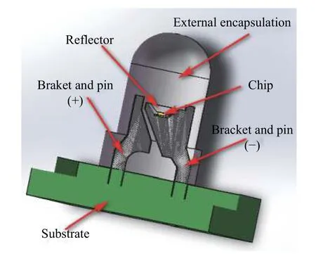
Fig. 1 The 3D model of a single LED

Tab. 1 Thermal conductivity of LED packaging material

Tab. 2 LED’s working parameters
Asshown in Tab. 2,hais the convection coefficient of the contact surface between the LED model and air, and the corresponding value was determined by analyzing experimental results.Tsuris the ambient temperature. The input power of a single LED chip isP=0.012A×1.9V=0.0228W. 80%of input power in the LED is converted into heat energy and the rest is converted into light energy[25].Therefore, the heating power of a single LED isPth=0.01824W. The volume of a single LED is regarded asV=9.439×10⁻¹²m3after analyzing an LED in an experiment. The LED chip is regarded as a whole light, and thus the internal heat generation on the chip isH=Pth/V=1932418560W/m3. Finally, the relevant simulation results are shown in Fig. 2 (Color online). Then the maximum and minimum temperatures of the LED model are 40.53 °C and 36.36 °C, respectively.
Based on the above parameters, a single LED model was tested. Firstly, the LED was lit for a period of time. After its temperature became steady, the maximum and minimum temperatures of its surface were collected using an infrared thermal imaging camera. Finally, after three similar experiments with the same parameters, the LED surface temperatures were found to be as shown in Tab. 3. For specificity,the LEDs used in the experiment are red.

Fig. 2 Surface temperature distribution of a single LED model
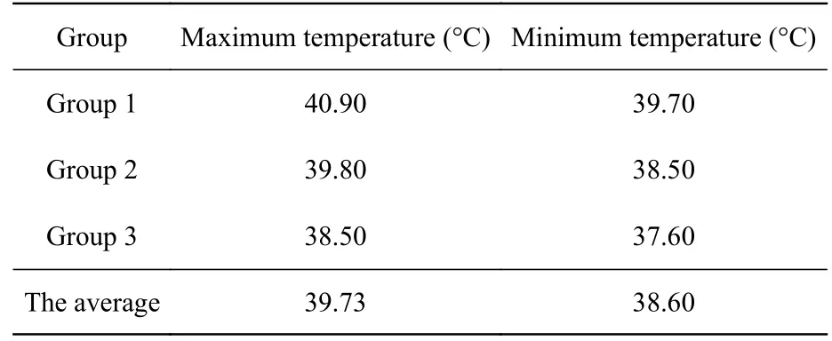
Tab. 3 Surface temperatures of a single LED model in experiments
Considering the experimental error, the maximum and minimum temperatures of the LED surface are respectively 40.07 °C and 36.83 °C in simulations. In addition, the averages of the maximum and minimum temperature on the LED surface are respectively 39.73 °C and 38.60 °C in experimental conditions.
Overall, the error between the experimental data and simulated data is within 2.00 °C, which is allowable. Therefore, the LED junction temperature and surface temperature in simulations can be viewed as the actual LED junction temperature and surface temperature in experiments. Finally, the LED thermal resistance is obtained as:

whereTjlrepresents the LED junction temperature andTsis the average surface temperature of the LED, these parameters are from thermal simulation a nalysis. In addition, 20% of the input power in the LED is converted into light, and the value of ηVis 0.2. After the relevant data are substituted into Equation (3), LED thermal resistance isRth−js=165.08K/W.
3 The junction temperature characteristic of same-color light in an LED array
The thermal dissipation performance of illumination will be greatly influenced by the junction temperature characteristics of the same-color light.Considering this will be helpful to the thermal dissipation design of LED arrays illumination. The junction temperature characteristics of homochromatic LEDs in strip-type and ring structure illumination will be developed.
3.1 Strip-type structure illumination
Taking two LEDs as an example, the case where two adjacent LEDs in strip-type formation is studied and analyzed based on the thermal resistance model of a single LED mentioned above.Firstly, two adjacent LEDs are used for modeling.The diameter of one LED is 3.0 mm and the distance between these two adjacent LEDs is 4.0 mm while the directions of their positive and negative pins match. Parameters used in the simulation, such as internal heat generation on the LED chips and the convection coefficient, all are set in accordance with the parameters described in Section 2. The relevant simulation results are shown in Fig. 3 (Color online).
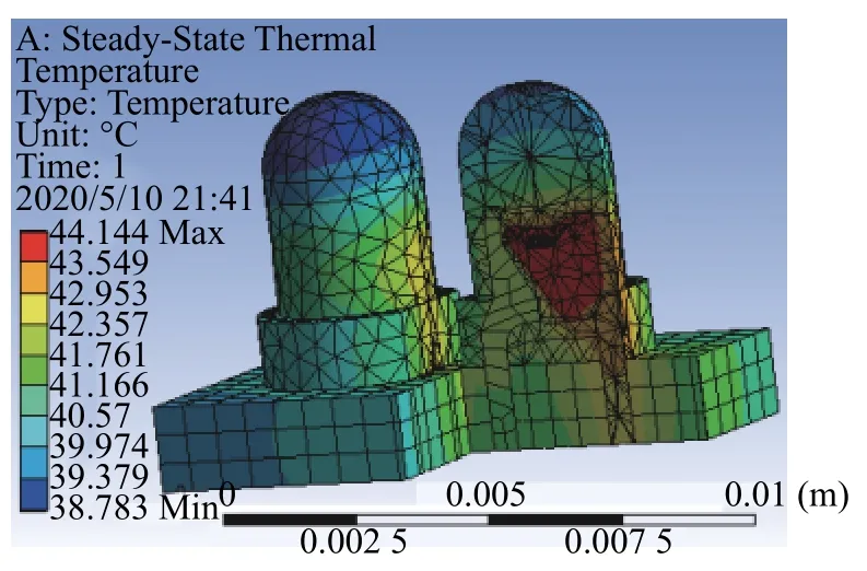
Fig. 3 Simulation results of the model with two adjacent LEDs
As shown in Fig. 3, the temperature at the LED chip is the highest, reaching 44.14 °C, and the temperature at the top of the LEDs is the lowest, falling to 38.78 °C. The LED junction temperature cannot be measured directly in the experiment. Thus, by studying the average surface temperature of the two adjacent LEDs and combining the LED’s thermal resistance as calculated in Section 2, the LED junction temperature can be obtained by Equation (2).
Next, starting with a separating distance of 4.0 mm and ending with a distance of 6.0 mm, the gradient is 0.2 mm. Eleven sets of data were collected by the ANSYS finite element analysis software to study the relationship between different center distances and the LEDs’ surface temperature. The relevant data is shown in Tab. 4. Its fitting equation can be expressed by the least square method:

where,dsandTsavgrepresent the center distance and average surface temperature of two adjacent LEDs,respectively.
This equation should be validated by experiments. Firstly, the center distance is 5.0 mm while the relevant experimental parameters, such as the LEDs’ input power, convection coefficient and ambient temperature, are consistent. Secondly, after the LEDs work in a steady state, the maximum and minimum values of their surface temperatures are captured by an infrared thermal imaging camera. Then,their average is used to represent the average surface temperature of an LED. Finally, in order to reduce the error, three groups of experimental data are obtained. The results of the analysis are shown in Tab. 5.

Tab. 4 Average temperature of the LED surface with different center distances in simulations

Tab. 5 The measurement and analysis of LEDs surface temperatures
As shown in Tab. 5, the fitting error rate was less than 3.00%, which indicates that the average surface temperature of two adjacent LEDs can be obtained by Equation (4). Therefore, the actual junction temperature of two adjacent LEDs can be expressed as

Assuming the junction temperature properties of more than two adjacent LEDs can be obtained by Equation (5). In order to validate this hypothesis, the junction temperature properties of three and four adjacent LEDs are analyzed by the ANSYS finite element analysis software. The related five groups of data obtained in experiments are displayed in Tab. 6.

Tab. 6 Junction temperature properties of three and four adjacent LEDs
The maximum error among data in Tab. 6 is less than 4.00%, which indicates that the junction temperature properties of three and four adjacent LEDs can be expressed by Equation (5) and still fall within the allowable error.
Similarly, the junction temperature characteristics of each LED array in strip-type structure illumination can also be calculated by Equation (5).
3.2 Ring structure illumination
The method for solving the junction temperature properties of ring structure illumination is the same as that of strip-type structure illumination. The model of LED ring structure illumination is shown in Fig. 4. Furthermore, the zeroth layer LED array of ring structure illumination is taken as an example for analysis. Its top view is shown in Fig. 5.
From Fig. 4 and Fig. 5, the relevant equations can be expressed as the following:

wherel1andr0are the perimeter and radius of the ring array, respectively. Meanwhile,l2andN0are the arc length between two adjacent LEDs and the number of LEDs in the ring array, respectively.l3is the straight-line distance from the LED substrate to the point that the central axes of the two adjacent LEDs meet. φ is the angle between the generatrix of the ring structure and the view plane, while α represents the angle between the central axes of the two adjacent LEDs. In addition,is the center distance and is defined as the straight-line distance between the adjacent LEDs’ chips, andh1is the straight-line distance from LED chip to the substrate.

Fig. 4 The model of LED ring structure illumination

Fig. 5 Top view for the zeroth layer LED array of ring illumination
The center distancecan be obtained by Equation (6)~(10) as:

Finally, the junction temperature characteristic of two adjacent LEDs in the zeroth layer LED array can be expressed as Equation (12) by analyzing Equation (5) and Equation (11).
Similarly, the junction temperature characteristic of theith layer of the LED array in the ring structure can be obtained by Equation (12) after confirming the corresponding parameters ofriand

3.3 The junction temperature characteristic of the mono-color(red) LED array
In structure illumination, the junction temperature characteristic of the mono-color(red) LED array can be expressed as follows based on the above thermal analysis of the LED strip and ring structure illumination.

wheredis the center distance between adjacent LEDs in an array,bis the slope of the fitting line whileCis a constant value. Moreover,bandCare parameters obtained by the least squares method.
4 A thermal dissipation design method for LED arrays structure illumination
In vision systems, high working temperature of structure illumination not only affects the light intensity, but also causes irreversible damage to illumination, which makes it difficult to capture a qualified image. Therefore, the thermal dissipation performance of structure illumination has great significance in improving vision system performance.The thermal dissipation design of mono-color LED structure illumination will be analyzed based on specific parameters involving specially appointed engineering applications.
4.1 The thermal performance analysis for LED arrays structure illumination
As shown in Fig. 4, based on the given conditions, ring structure illumination is an example model of LED array structure illumination. In Fig. 4,0,1,···,nis the number of layers in the LED ring arrays. In addition, the radius of each LED ring array isri,i=0,1,···,n. In the axial section,Diis defined as the distance between theith layer LED array and the (i+1)t h layer LED array,i=0,1,···,n−1.
In order to evaluate the thermal dissipation performance of existing structure illumination, the following equations are used as:

whereTjavgis the overall working average junction temperature of structure illumination, andNrepresents the total number of LEDs.Niis the number of LEDs in theith layer array, andTijis the working junction temperature of theith layer array.Tjhis defined as the highest temperature selected from the junction temperatures of all LED arrays in the illumination.aiis the temperature coefficient of theith layer LED array affected by its surrounding LED arrays.ai≥1 and it can be obtained through experimentation.diis the center distance between adjacent LEDs in theith layer array,i=0,1,···,n.Therefore, according to the existing structure’s parameters, the values of parametersTjavg,TjhandTijcan be obtained. On this basis, the thermal dissipation performance of structure illumination can be evaluated with reference to related technical standards.
Similarly, the thermal dissipation performance of strip-type structure illumination can be evaluated in the same way.
4.2 A thermal dissipation design method for LED array structure illumination
Assuming the input power and luminous efficiency of a single LED arePand ηv, respectively,based on the determination of related parameters, a mono-color LED structure illumination with excellent thermal dissipation performance can then be designed to ensure that the maximum junction temperature of the LED does not exceed the ceiling temperatureTR.
Taking the ring structure illumination as an example, the thermal dissipation problem will be transformed into an optimization design equation based on the built model in Fig. 4. In other words, in the optimization equations, parameters ofn,ri,φ andDiare inherent parameters of the structure’s illumination. It needs to confirm the value ofdiand calculate the corresponding value ofNito ensure the LED junction temperature is limited to the value ofTR,i=0,1,···,n. Based on the analysis mentioned above, the optimization design equations can be expressed as:

For ring structure illumination:

Subject to

whereTiis the calculated junction temperature of theit h layer array andkiis related to the temperature coefficientai,i=0,1,···,n.
For clarity, the proposed method can be converted to the following proposed method of hierarchical design to simplify the design process. In other words, it can be decomposed into two subproblems. One is the thermal dissipation design problem of the single-layer LED array, and the other one is the thermal dissipation design problem of multi-layer LED arrays.
4.2.1 The thermal dissipation design problem of the single-layer LED array
As for the thermal dissipation problem of the single-layer LED array, the input powerP, luminous efficiency ηvand thermal resistanceRth−jsof the illumination can be confirmed based on the actual conditions, which consequently simplifies Equation(17). Then, the center distancediis easy to be confirmed according to the junction temperature properties of LEDs and the cooling requirements. Finally,the thermal dissipation design method of the singlelayer LED array is finished.
4.2.2 The thermal dissipation design problem of multi-layer LED arrays
Based on the designed single layer LED array illumination, the multi-layers LED arrays illumination is matched and eventually obtained according to the design process shown in Fig. 6. WherePiis the input power of a single LED in theith layer array, and 0<ki≤1. In addition, the value ofkiis determined experimentally.
Firstly, to the zeroth layer LED array, the input powerP0and center distanced0are designed by trial and error, which limits the average junction temperature of an LED in the array withink0T0j.Then, the design of the zeroth layer LED array is finished. Similarly, the design of theith layer LED array can be completed in the same way,i=1,2,···,n. After finishing the design of all LED arrays, the LED array structure illumination is preliminarily completed. Secondly, the average junction temperature of each layer LED array is measured and calculated after lighting the structure for a period of time. Afterward, whether the acquired average junction temperature of each array is limited within the temperatureTRneeds to be confirmed. If it is limited withinTR, then the design of the multilayer LED array is completed. Otherwise, it means that the average junction temperature of theith layer LED array exceedsTR, which is not permitted. To solve such a problem, its corresponding parameterkishould be adjusted according to the actual situation.Furthermore,Pianddialso need to be redesigned to limit the average junction temperature ofith layer LED array within the newkiTij. After the adjustment, whether the average junction temperature of each LED array is limited within the temperatureTRneeds to once again be confirmed. If it is, then the design of the multi-layers LED arrays is completed.Otherwise, the above adjustment should be repeated until the structure illumination design is finished.

Fig. 6 The thermal dissipation design process of multi-layer LED arrays
5 Experimental results and analysis
In this experiment, the thermal dissipation design problem of mono-color multi-layer LED array illumination is illustrated by the proposed method, which considers the LED junction temperature measurement as the application background. According to the application conditions of LED structure illumination, its parameters, such as the internal heat generation on the chip and convection coefficient and ambient temperature, are consistent during the simulation analysis. As shown in Fig. 7 (color online), the mono-color (red) LED strip-type arrays structure illumination with 5×9 is designed based on the proposed design method.

Fig. 7 The 3D model of strip-type structure illumination
5.1 Strip-type structure illumination
Assuming the LED junction temperature is limited to 45.00 °C. Then,Tijis equal to 45.00 °C in the proposed method. Moreover, the center distance of two adjacent LEDs in an array and that of two adjacent LED arrays are designed to respectively be 5.55 mm and 5.00 mm in strip-type structure illumination. Finally, as shown in Fig. 7, the model of the strip-type structure is built. Besides, its thermal analysis is performed, and its LED junction temperatures are also obtained, as shown in Fig. 8 (Color online). The details of one LED in strip-type structure illumination is shown in Fig. 9 (Color online).

Fig. 8 The thermal model of strip-type structure illumination
As can be seen from Fig. 8 and Fig. 9, the maximum junction temperature of the LEDs is 44.85 °C,which is less than 45.00 °C. Furthermore, their error is −0.33% and less than 1.00%. These results indicate that the illumination’s thermal stability is excellent. In addition, LEDs in the central area have higher operating temperatures than those at the edge. The reason could be that the closer the LED is to the central area, the more affected it is by its surrounding LEDs. Then its thermal dissipation rate relatively decreases under the same working conditions. Consequently, it accumulates more heat and has a higher temperature. On the other hand, the operating temperature of an LED at the edge is lower,which is owing to the following reasons: firstly, the number of its surrounding LEDs is less, which makes it less affected by heat. Secondly, a better thermal dissipation condition is provided to it because of the edge structure, such as the distance between the edge and outermost LEDs, and the air convection on the side of the edge. Experimental results show that the proposed method is effective for designing a thermal dissipation structure for strip-type structure illumination.
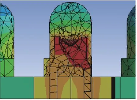
Fig. 9 The details of one LED in strip-type structure illumination
5.2 Ring structure illumination
Si milarly, if one were to assume that an LED’s junction temperature in ring structure illumination is limited to 40.00 °C, then based on the structure parameters ofr0=23.0mm, φ=23.0° andd0=d1=d2=d3=6.0mm ,Ni(i=0,1,2,3,4), a new structure is designed by applying the proposed design method and it represents the number of LEDs in theith layer array. The specific values ofNiare shown in Tab. 7.

Tab. 7 The number of LEDs in each layer array for ring structure illumination
The mono-color (red) five-layer LED ring array structure illumination is shown in Fig. 10, the model of ring structure illumination is built based on the proposed method. Its thermal analysis is performed by using ANSYS finite element analysis software, as shown in Fig. 11. The details of one LED in ring structure illumination is shown in F ig. 12.

Fig. 10 The 3D model of ring structure illumination

Fig. 11 The thermal model of ring structure illumination
It can be seen from Fig. 11 (Color online) and Fig. 12 (Color online) that the maximum junction temperature of its LEDs is 40.13 °C, which is slightly higher than 40.00 °C. Furthermore, their error is 0.33% and less than 1.00%. The illumination’s temperature distribution is generally the same,which is unlike strip-type structure illumination.Overall, the proposed ring structure illumination thermal stability is excellent. However, it is noted that temperature distribution at the edge of the zeroth layer array is not the same as that at the edge of the 4th layer array, where that of the former is higher than that of the latter. The possible reasons for this phenomenon are as follows: firstly, the center distance between two adjacent LEDs in the zeroth layer array is less than that in the 4th layer array. Secondly, in the generatrix direction of the ring structure’s illumination, the distance between LED’s center in the zeroth layer array and its corresponding edge is 3.0 mm, while the distance between LED’s center in the 4th layer array and its corresponding edge is 4.0 mm. It indicates that LED thermal dissipation in the zeroth layer array is relatively poor, which results in a slower thermal dissipation rate, more thermal accumulation and a relatively high temperature. Experimental results show that the proposed method is also effective for designing the thermal dissipation structure of ring structure illumination.

Fig. 12 The details of one LED in ring structure illumination
5.3 Experimental comparison
The thermal dissipation of ring structure illumination is more complex than strip-type structure illumination. Therefore, in order to further evaluate the effectiveness of the proposed method, the ring structure illumination is taken as an example for experimental verification. Based on the design parameters provided in Section 5.2, ring structure illumination is made. Specifically, the zeroth layer lighting of the LED array ring structure illumination is shown in Fig. 13.

Fig. 13 The zeroth layer lighting of the LED array ring structure illumination
The ring structure illumination was lit for a period when the relevant parameters, such as the internal heat generation on the chip, convection coefficient and ambient temperature, were consistent with those in simulation. After its temperature became stable, an infrared thermal imaging camera was used to capture the maximum and minimum temperature of each LED surface. Then, the maximum average surface temperature of the LED in the structure was 37.90 °C by calculation and comparison. Finally, the maximum junction temperature of the LEDs was obtained as 40.91 °C using Equation(3). It is slightly higher than the 40.13℃ obtained by simulation, giving an error of 1.94%. In addition,it is also slightly higher than the ceiling temperature of 40.00 °C, giving an error rate of 2.28%.
Experimental results show that the maximum junction temperature of structure illumination is higher than that of the simulation and the ceiling temperature. The possible reasons for the error are as follows: firstly, the manufacturing error of structure illumination should be controlled accurately.The uneven solder at the LED pins can lead to poor thermal dissipation of structure illumination.Secondly, measurement error is also an effective factor. For example, there is deviation when the infrared thermal imaging camera captures the temperature because of the LED emissivity, measurement distance and other factors. However, these error rates are both less than 3%, which is within the allowable level of error. The illumination thermal stability is still good. Experimental results validate the effectiveness of the proposed method.
6 Conclusions
A thermal dissipation design method for LED array structure illumination is proposed in this paper. The main conclusions are as follows:
(1) The proposed thermal resistance model of a single LED can be used to calculate the LED thermal resistance effectively.
(2) The proposed junction temperature model for LED arrays structure illumination can be applied to obtain the junction temperature of the structure quickly after confirming the LED’s thermal resistance and center distance.
(3) Experimental results show that the junction temperature deviation is −0.33%~0.33% by simulation and is 2.28% by experimentation when using the proposed thermal dissipation design method,which indicates that the proposed method is an effective thermal dissipation design for LED array structure illumination.
Further work will focus on studying the thermal dissipation design problem of multi-color LED array structure illumination.
猜你喜欢
汕头大学学报(自然科学版)(2020年4期)2020-12-14
汕头大学学报(人文社会科学版)(2020年5期)2020-11-03
汕头大学学报(人文社会科学版)(2020年2期)2020-06-24
今日农业(2020年24期)2020-03-17
近代史学刊(2019年1期)2019-08-24
照明工程学报(2019年3期)2019-07-09
汕头大学学报(人文社会科学版)(2019年3期)2019-06-03
黑龙江民族职业学院信息(2017年6期)2018-01-03
黄河之声(2017年10期)2017-08-09
玩具世界(2017年4期)2017-07-21
