
Multi-layer structure formation of relativistic electron beams in plasmas
2022-03-10 03:49XiaojuanWANG王晓娟ZhanghuHU胡章虎andYounianWANG王友年
Plasma Science and Technology 2022年2期
Xiaojuan WANG(王晓娟),Zhanghu HU(胡章虎)and Younian WANG(王友年)
School of Physics,Dalian University of Technology,Dalian 116024,People's Republic of China
Abstract A two-dimensional electromagnetic particle-in-cell simulation model is proposed to study the density evolution and collective stopping of electron beams in background plasmas.We show here the formation of the multi-layer structure of the relativistic electron beam in the plasma due to the different betatron frequency from the beam front to the beam tail.Meanwhile,the nonuniformity of the longitudinal wakefield is the essential reason for the multi-layer structure formation in beam phase space.The influences of beam parameters(beam radius and transverse density profile)on the formation of the multi-layer structure and collective stopping in background plasmas are also considered.
Keywords:multi-layer structure,beam phase space,relativistic electron beam,plasma based beam dump,PIC
1.Introduction
The interaction of relativistic electron beams with plasmas has gained an intensity level of attention in various applications,such as high energy density physics[1],inertial confinement fusion[2]and plasma-based accelerators(PBAs)[3-11].In the fast ignition,the ignition is achieved by depositing energy into the dense core with the relativistic electron beams.PBA[3]was firstly proposed by Tajima in 1979.By employing a high intensity laser or relativistic charged particle beam as the driver,PBA schemes are categorized into two kinds:laser wakefield acceleration[3,5,9]and plasma wakefield acceleration[4,5,12].The acceleration gradients of PBA are currently able to achieve an order of several hundred GeV m-1,much larger than those produced by conventional radio frequency accelerators.With continuous progress in high power laser technology,multi-GeV energy gain of electrons is achievable over a short distance in the experiments[9].Meanwhile,a safety design of the beam dump[13-16]is urgently acquired to decelerate particles into a safe energy region without radiation.Thus,based on the collective electromagnetic field of short particle bunches in the plasma,plasma-based beam dump has recently received tremendous interest to develop safer and greener facilities.
Many simulations and analytical works[13-18]have been carried out to investigate plasma-based beam dump.The strong collective stopping of few-fs electron beams inside mm-scale underdense plasma was firstly demonstrated in two independent experiments[19].It is shown that the plasma beam dump can be the most straightforward application for absorbing the kinetic energy of the EuPRAXIA beam over short distance[13-16].Generally,two types of plasma beam dump(passive beam dump and active beam dump)are considered.In the passive beam dump,relativistic electron beam travels through the undisturbed plasma and achieves the deceleration by beam self-driven wakefield.Tailored plasmadensity profiles in the passive scheme are demonstrated to improve the beam-energy loss[13].
In the active scheme,relativistic electron beam propagates with the wake excited by laser pulse and then disposes large energy in the plasma due to the self-excited and laser-driven wakefields.The plasma-based beam dump can greatly improve the overall compactness of PBA and reduces high-energy radiation caused by scattering in the material beam dump.
It should be noted that in actual applications,the energetic electron beams might be defocused and have a radius much larger than plasma skin depth in a plasma-based beam dump.In this work,we consider in detail the density evolution and energy deposition of relativistic electron beams with large radius(larger than plasma skin depth)in plasmas and mainly focus on the beam phase space evolution and energy deposition.Multi-layer structures in beam phase space are clearly observed.The twostream instability(TSI)with short electron beam is limited in the present simulations.The current filamentation instability(CFI)breaks up the relativistic electron beam into small filaments and causes large energy deposition in the plasma.The paper is organized as follows.A two-dimensional(2D)particle-in-cell(PIC)simulation model is presented in section 2,along with beam and plasma parameters.We analyze the formation of multi-layer structure in section 3.The influences of beam parameters on the multi-layer structure and beam phase space are studied in detail in section 4.Finally,conclusions are given in section 5.
2.Simulation model
A 2D3V electromagnetic PIC simulation code IBMP[20,21]is employed to study density evolution and collective stopping of electron beams in background plasmas.A cell size of△x=△y=2.56×10⁻⁹m,time step of △t=5.12×10⁻¹⁸s and nine particles per cell per species are used here.A moving-window approach is used in these simulations to reduce the computation time.It carries out in the laboratory frame,in which the simulation window is shifted by a distance in the beam propagation direction every a few time steps(which can be set in the simulation)to ensure that the simulation window moves with the electron beam on the average.Absorbing boundary conditions are adopted in both longitudinal(along thex-axis)and transverse(along theyaxis)directions.We model a hydrogen plasma with a real ion massmi/me=1836 and chargeZi=efor simulations,which fills the simulation box uniformly at the initialization stage.The density and electron temperature of the plasma are set to benpe=1027m-3andTpe=4 eV respectively.Electron beams with energyEbe=113 MeV and densitynbe=0.1npeare adopted in the simulations.The longitudinal spatial profile of the electron beam is assumed to be Gaussian with a width(FWHM)τbe=π/ωpe,in which ωpeis the plasma electron frequency.We keep relativistic electron beam density fixed and investigate the effects of beam parameters(beam radius and transverse density profile)in detail in the next sections.
3.Multi-layer structure formation of relativistic electron beams
We first show here the structure evolution of the electron beam with a Gaussian transverse density profile and radiusrb=5c/ωpe.Here,cis the speed of light and ωpe=For the electron beam with radius much larger than plasma skin depthc/ωpe,the interaction of beam current and plasma return current is subject to the CFI.The beam density evolutions in the plasma at six travel times are clearly depicted in figure 1.Some filaments of the electron beam are shown in figure 1(b).It should be noted that the competition between the CFI and beam focusing effect can be observed in the figure.From figure 1(c),one can see that the beam is strongly focused before the CFI is fully developed,in which the decrease of the beam radius at the tail and the increase of the beam density can be clearly observed.Once a short electron beam is injected into the plasma,plasma electrons are radially expelled from the beam paths and ions do not respond because of their heavy mass(figures 2(c)-(d)).Under the restoring force of the immovable plasma ions,some expelled plasma electrons come across the beam axis and form the oscillating peak density behind the beam driver[17].As a consequence,the space charge oscillation and then the plasma wakefield are formed at the back of beam.The longitudinal wakefield[22-24]excited in the linear regime is expressed approximately by
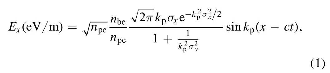
wherenpeandnbeare the plasma and beam density in m-3respectively,σxand σyare the rms dimensions of the beam,andkp=ωpe/cis the plasma wave number.Figure 2 clearly displays the distributions of the wakefield at ωpet=280.5.The transverse electric fieldEyat the tail of the beam is seen to strongly focus the beam electrons,which can be observed from figure 2(a).Thus,under the focusing effect of the transverse wakefield(EyandBz),the beam density at the tail increases significantly and reaches 1027m-3in figure 1(e),which is about 10 times larger than the initial value.From equation(1),the magnitude of the longitudinal electric fieldExis estimated to be 4×10¹¹V m-1with the given plasma and beam parameters(figure 1(a)).Once focused,the beam density increases and approaches plasma density(figure 1(c)),the magnitude ofExincreases significantly and reaches 1.5×10¹²V m-1,as indicated in figure 2(c).
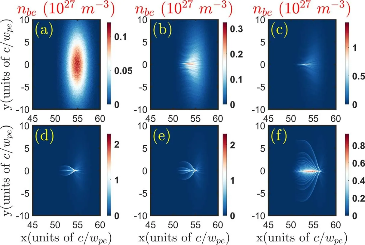
Figure 1.Structure evolutions of relativistic electron beam with rb=5c/ωpe propagating through the plasma.Snapshots at six selected times are depicted with(a)ωpet=0,(b)127.4,(c)159.3,(d)223.1,(e)280.5 and(f)784.5.
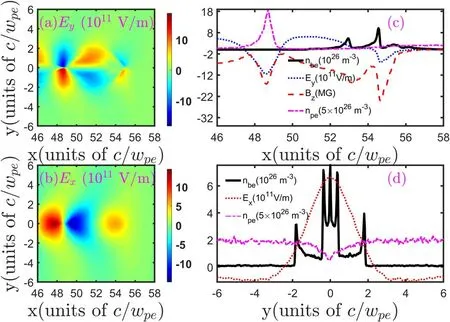
Figure 2.Distributions of transverse electric field Ey(a)and longitudinal wakefield Ex(b)excited in the plasma at the travel time ωpet=280.5.The spatial profiles of transverse wakefield(c)(Ey and Bz)along the x direction at y=0.5c/ωpe and longitudinal wakefield(d)Ex along the y direction at x=52.5c/ωpe are displayed.The longitudinal and transverse spatial profiles of beam density nbe are also shown in(c)and(d)for illustration.The slice distributions of plasma electron density along the x direction at y=0 and along the y direction at x=52.5c/ωpe are also depicted in(c)and(d).
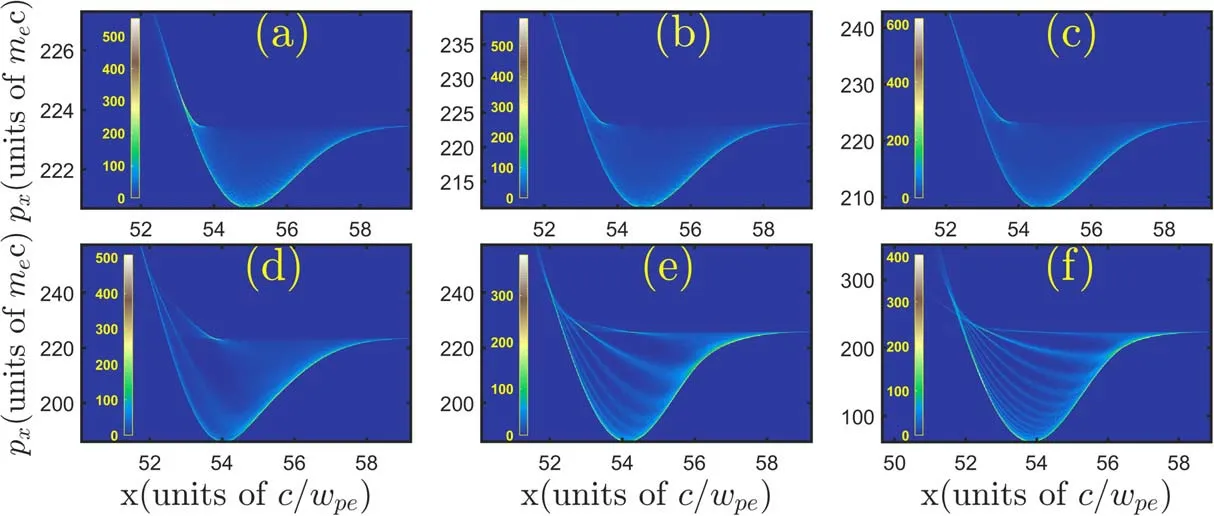
Figure 3.Distributions of longitudinal phase space for relativistic electron beam with rb=5c/ωpe at the six different travel times:(a)ωpet=0,(b)127.4,(c)159.3,(d)280.5,(e)531.2 and(f)784.5.
By inspecting figures 1(d)-(f),we note here the formation of the multi-layer structure(figure 1(d))and later growth of the slice numbers(figure 1(f))at the tail of the beam.To clearly explain this,we also display the longitudinal slice distributions of the transverse wakefield aty=0.5c/ωpein figure 2(c).Meanwhile,the longitudinal and transverse spatial profiles of beam densitynbeare also shown in figures 2(c)and(d)for illustration respectively.Under the focusing force of the transverse wakefield at the tail,the betatron frequency of the beam electron is relatively larger.Thus,the slice structure is firstly observed at the tail,as indicated in figure 1(d).The transverse wakefieldEy-cBzis essentially close to zero at the front.This implies that the slices at the beam head are also gradually presented in figure 1(f)as the travel time increases.Furthermore,the radius of the slice close to the beam front is larger than that at the beam tail,as clearly shown in figures 1(e)and(f).
Representative snapshots of the longitudinal phase space are displayed in figure 3.Prior studies[24,25]have demonstrated that majority of the beam electrons at the middle are decelerated and a small amount of beam electrons at the tail are accelerated obviously beyond the initial energy,which can be clearly identified in figures 3(a)-(f).It can be envisioned by noting that the longitudinal wakefieldEx(figure 2(b))is positive at the middle of the beam and negative at its higher energy tail relatively.The most attractive feature of figures 3(e)and(f)is the formation of multi-layer structures in the longitudinal phase space,indicating the beam energy modulation in addition to the collective stopping.To show this clearly,the corresponding longitudinal wakefieldExand density of the beam electronnbealong they-axis at the positionx=52.5c/ωpeare displayed in the figure 2(d).It is obvious from this figure that the longitudinal wakefieldExis nonuniform in the transverse direction and decreases gradually towards beam edge.As a result,the electrons at the beam edge are expected to have higher energies than those at the beam axis.Figure 3(f)clearly illustrates that the kinetic energy of slice is nonuniform and then the layers structure of longitudinal phase space is formed consequently.
4.Effects of beam radius and transverse density profile
We proceed by considering the influences of different radius on the density evolution and collective stopping of electron beams with high energy traveling through background plasmas.Three cases are considered in the simulations:rb=c/ωpe,5c/ωpeand 7.6c/ωpe.The centers of the electron beams for three cases are located atx=23c/ωpeandy=0 initially.The other parameters are the same as presented in section 2.We compare the longitudinal slice of the longitudinal wakefieldExat the positiony=0 for three cases in figure 4(a).In terms of short electron beam,quantitative characteristics ofExare beam charge dependent.The electron beam with a larger radius excites a stronger wakefield due to a higher beam charge,as indicated in figure 4(a).For the electron beam withrb=c/ωpe,the magnitude of longitudinal wakefieldExis seen to be 300 GV m-1from equation(1),showing agreement with the figure.Meanwhile,the magnitude further increases to 800 GV m-1for the caserb=7.6c/ωpe.The significant beam energy loss due toExcan be expected in figure 4(b).Some of beam electrons are seen to have a kinetic energy of 35 MeV after a travel time of ωpet=704 for the case ofrb=7.6c/ωpe,losing 70% of its initial energy.It should be noted here that multi-peaks in the beam energy spectrum can be identified in the figure due to the multi-layer structure.
Figure 5 presents detailed comparisons of beam density distributionsnbe((a)-(c))and longitudinal phase space((d)-(f))for three radius cases.The competition between the beam focusing effect and CFI can be clearly expected in figure 5(c).Some filaments at the beam front regions can be observed from the figure.The modulation of beam density(at the beam center regions)in the transverse direction due to the CFI can also be observed,indicating the competition between the beam focusing effect and CFI.As mentioned before,the transverse electric fields at the beam center(defocusing force)increase with the beam radius.Thus,comparing figures 5(a)-(c),one can find that the beam slice radius of multi-layer structure increases with initial beam radius.From the longitudinal phase space distributions,the multi-layer structure is more significant for relativistic electron beam with radiusrb≫c/ωpe(i.e.figures 5(e),(f)),indicating the significant nonuniformity ofExalong the transverse direction.
We also compare the density evolutions of electron beams with two transverse density profiles:Gaussian(figures 6(a),(c))and flat-top(figures 6(b),(d)).The radius of the electron beam is selected to berb=7.6c/ωpe.For the flat-top distribution,the beam electrons are only focused at the beam edge and the CFI can be fully developed.After filaments merging,three electron filaments with small radius are formed,as indicated in figure 6(d).Figure 7 shows comparisons of the longitudinal beam phase space((a)and(b))and energy spectrum((c)and(d))with two density profile cases.The multi-layer structure of the longitudinal phase space for the Gaussian distribution is clearly indicated in figure 7(a).However,for the flat-top case(figure 7(b)),the energy spread of beam electrons is shown to be smaller,which can also be identified by comparing figures 7(c)and(d).In addition,the peak in the beam energy spectrum is seen to move to the low energy side for the flat-top case and the number of beam electrons with high energy(113 MeV)decreases.
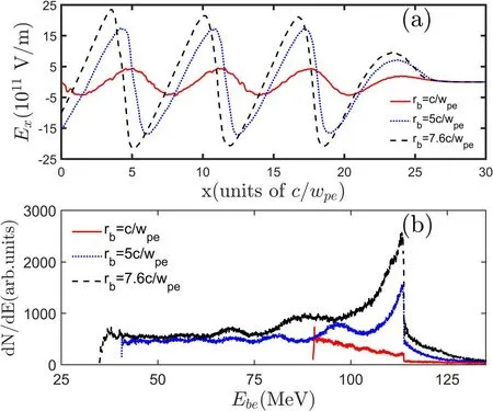
Figure 4.Longitudinal spatial profiles of longitudinal wakefield Ex(a)at y=0 and the energy spectrum of electron beam(b)for three beam radius cases: rb=c/ωpe,5c/ωpe and 7.6c/ωpe.The beam travel time is ωpet=704.
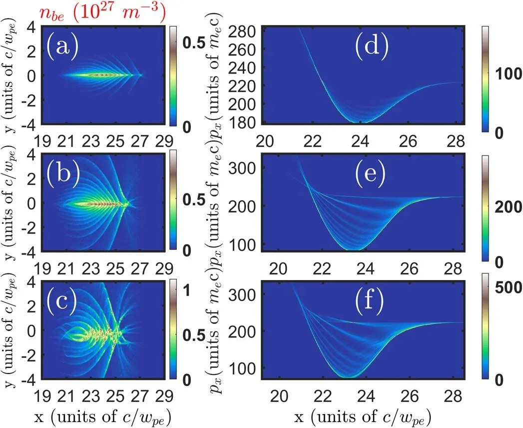
Figure 5.Comparisons of the electron beam density nbe((a)-(c))and longitudinal phase space((d)-(f))for rb=c/ωpe,5c/ωpe and 7.6c/ωpe.The selected travel time in the figure is ωpet=704.
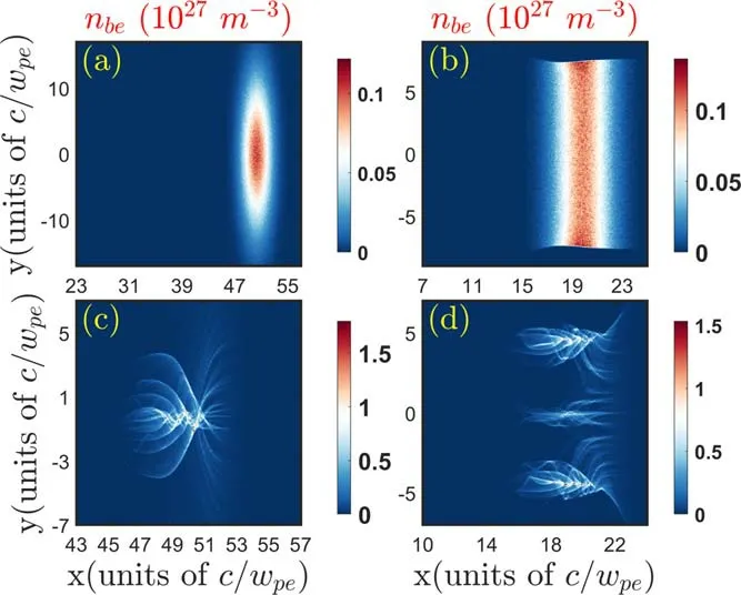
Figure 6.Influences of transverse density profiles(Gaussian((a)and(c))and flat-top((b)and(d)))on the density distributions of the electron beam at two travel times(ωpet=0((a)and(b))and ωpet=531.2((c)and(d))).
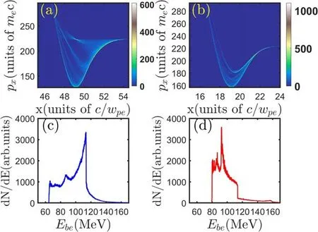
Figure 7.Distributions of the longitudinal phase space and energy spectrum of beam electrons with different density profiles:Gaussian((a)and(c))and flat-top((b)and(d)).The travel times in the figure is ωpet=531.2.
The multi-layer structures indicate that the beam electrons with high energy are located at the beam edge(where the magnitude of longitudinal wakefield is smaller than that at the beam center),which is negative for the beam stopping.As indicated in figure 7(c),a peak can be observed at the high energy regions.This cannot be fixed with a plasma of different density.The reason is that the transverse wakefield coexists with the longitudinal wakefield(which is for collective beam stopping)and the nonuniformity of the transverse field is mainly determined by the beam density profile.The beam duration is a critical parameter for the multi-layer structures in this work.For the beam duration larger than the plasma period,the charge neutralization can be achieved and the TSI can be excited.The coupled TSI and CFI develops and the multi-layer structure cannot be observed anymore.The magnitude of the transverse wakefield depends on the beam density,but is independent on the beam energy.Therefore,as the beam energy increases,the structure is formed on a longer time scale due to a heavier beam electron mass.Meanwhile,as the ratio of beam density to plasma density increases,a stronger wakefield can be expected and the structure is formed on a shorter time scale.These findings may help us to understand the dynamic of the beam with large radius propagating through the plasma,which should provide some references for the plasma based beam dump.
5.Conclusion
Motivated by science and commerce,investigation of beamplasma system is a topic of significant interest.The density evolution and collective stopping of relativistic electron beams in plasmas are frequently encountered in many applications,such as the fast ignition and plasma-based beam dump.The wakefield excited by short electron beam plays a vital role in the time evolutions and energy loss.The longitudinal and transverse wakefields are responsible for the beam stopping and focusing respectively.In this work,2D PIC simulations were used to study the density evolution and collective stopping of the short electron beam withrb≫c/ωpetraveling through the plasmas.Due to the longitudinal nonuniformity of the transverse wakefield,the multilayer structure is formed in the plasmas.Furthermore,the nonuniformity of the longitudinal wakefield in the transverse direction contributes to the formation of the multi-layer structure in beam phase space.The longitudinal wakefield causes a large energy spread of beam electrons and significant beam energy extraction in dense plasmas.These dynamic evolutions are essential for the plasma-based beam dump.Dimensional effect(2D versus 3D)in PIC simulation,as a key role,can change quantitative results significantly.Especially for the nonlinear interactions between the beam and plasma,the magnitude of wakefield generated by a short beam in background plasmas will vary a lot from 2D to 3D simulations.However,the nonuniformity of the transverse wakefield(EyandBz)in the longitudinal direction is the essential reason for the multi-layer structure formation,which is independent on the dimension of the simulation.Therefore,we believe that the findings in this work should also be presented in the 3D simulations.
Acknowledgments
This work is supported by National Natural Science Foundation of China(Nos.12 075 046 and 11 775 042).
 Plasma Science and Technology2022年2期
- Plasma Science and Technology的其它文章
- Investigation of short-channel design on performance optimization effect of Hall thruster with large height-radius ratio
- Mode structure symmetry breaking of reversed shear Alfvén eigenmodes and its impact on the generation of parallel velocity asymmetries in energetic particle distribution
- Interaction between energetic-ions and internal kink modes in a weak shear tokamak plasma
- Investigation of the compact torus plasma motion in the KTX-CTI device based on circuit analyses
- Anomalous transport driven by ion temperature gradient instability in an anisotropic deuterium-tritium plasma
- Nonlinear excitation of a geodesic acoustic mode by reversed shear Alfvén eignemodes