
Study on divertor plasma behavior through sweeping strike point in new lower divertor on EAST
2022-06-29 08:55YuQiangTao陶余强GuoShengXu徐国盛LingYiMeng孟令义RuiRongLiang梁瑞荣LinYu余林XiangLiu刘祥NingYan颜宁QingQuanYang杨清泉XinLin林新andLiangWang王亮
Chinese Physics B 2022年6期
Yu-Qiang Tao(陶余强) Guo-Sheng Xu(徐国盛) Ling-Yi Meng(孟令义) Rui-Rong Liang(梁瑞荣)Lin Yu(余林) Xiang Liu(刘祥) Ning Yan(颜宁) Qing-Quan Yang(杨清泉)Xin Lin(林新) and Liang Wang(王亮)
1Institute of Plasma Physics,Hefei Institutes of Physical Science,Chinese Academy of Sciences,Hefei 230031,China
2University of Science and Technology of China,Hefei 230026,China
3Institute of Energy,Hefei Comprehensive National Science Center,Hefei 230031,China
Keywords: EAST tokamak,divertor plasma,sweeping strike point,decay length
1. Introduction
In tokamaks, heat and particles exhausted from the hot magnetically confined plasma, stream along open magnetic field lines and mainly localize over lengths much shorter than the size of divertor target plates. For future reactors, the unmitigated heat load on divertor target is more than one order larger than the engineering safety limit,~10 MW/m2,which is a severe challenge.[1]Several solutions are proposed to mitigate the high heat load: distribute heat fluxes through manipulating divertor poloidal magnetic configurations, such as snowflake divertor[2]and super-X divertor;[3]facilitate detachment through trapping neutrals and impurities in a highly closed divertor,such as SAS divertor on DIII-D[4]and the new‘corner slot’divertor on EAST.[1]There is another simple and robust method, sweeping strike point, to spread the heat load over a large surface area. Sweeping strike point experiments have been successfully conducted in JET experiments,and this method may be adopted in the future campaign with 40 MW of source auxiliary heating power.[5]Similar concept,the fish tail divertor(FTD),has been proposed and experimentally performed on EAST,[6,7]which needs an additional alternating magnetic field coil behind the divertor. Some studies have so far found that sweeping appears to be compatible with implementation and use on DEMO.[8]
In this year,EAST superconducting tokamak has replaced the old lower graphite divertor with tungsten divertor to increase the power handling capacity to~10 MW/m2. The most attractive characteristic of this new divertor is the‘corner slot’,i.e.,a closed right-angle corner consisted by the horizontal target and vertical target. This special structure can bring the‘corner effect’,i.e.,when the outer strike point locates on the horizontal target plate near the corner,the horizontal target plate reflects impinging particles mostly towards the scrapeoff layer (SOL), where the particles are confined by the vertical target plate and trapped in the closed corner, thus high neutral pressure is achieved near the corner. The corner effect has been studied by SOLPS-ITER simulation.[1]
In this paper, the divertor plasma behavior will be studied through sweeping strike point in the new lower divertor on EAST. Owning to the powerful control ability of poloidal field coils, the plasma control system (PCS) adjusts the location of primaryX-point flexibly and controls the lower outer strike point sweeping from the horizontal target to the vertical target. Surface temperature will be monitored by infrared(IR) thermography to demonstrate that sweeping strike point can mitigate the heat load on divertor target. Plasma behavior,such as divertor particle flux and heat flux, will be diagnosed by divertor Langmuir probe array. To avoid the effect of probe tip damage, a method based on sweeping strike point is applied to get the normalized distributions on the divertor target,similar to the technique in the work.[9]And the decay lengths of divertor particle flux and heat flux,λjs,λq,will be discussed and compared with previous work.[10–12]
This paper is organized as follows: Section 2 describes the experimental setup and introduces the relevant diagnostics; Section 3 presents the experimental results and discussion. Summary is given in Section 4.
2. Experimental setup and main diagnostics
A series of sweeping strike point experiments have been conducted in EAST low confinement mode (L-mode) discharges with high RF heating power. The discharges are operated in lower single null(LSN)or double null(DN)divertor configuration. The central magnetic field isBt=2.4 T with the ionB×∇Bdrift direction into upper divertor. Figure 1(a)shows the configuration of one typical LSN shot#98332,calculated from EFIT magnetic reconstruction. The PCS controls theX-point moving towards low field side fromRx~159 cm(3 s) toRx~166 cm (8 s), whereRxis the major radius of the lowerX-point. Consequently,the lower outer strike point sweeps from the horizontal target to the vertical target,as seen in Fig.1(c). The distance between strike point and the corner is nearly linear with time,when the strike point locates on the horizontal target or vertical target,as shown in Fig.1(b).

Fig.1. In shot#98332,(a)the magnetic configurations at different times;(b)the distance(s)between lower outer strike point and the corner versus time(t)with linear fit on the horizontal target(s <0)and vertical target(s >0);(c)detail view in the lower outer divertor region with the distribution of divertor Langmuir probe array(Div-LP),the intersection angle θ (θ <90°)between the poloidal magnetic field and the target plate,and the pixel location N1,N2,N3 (red ellipses).
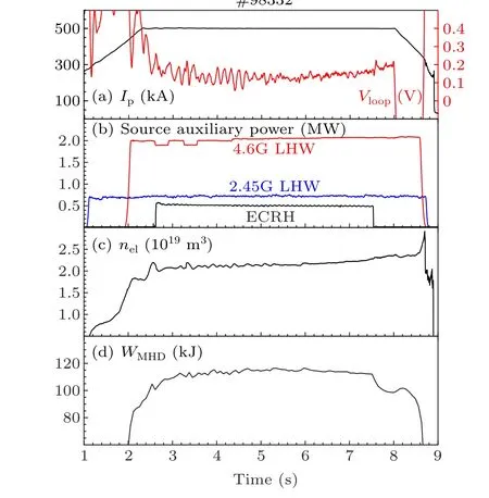
During these discharges, the plasma current isIp=500 kA in Fig. 2(a). The source auxiliary heating power isPtotal=3.2 MW including 0.7 MW from 2.45G low hybrid wave (LHW), 2 MW from 4.6G LHW, and 0.5 MW from electron cyclotron resonance heating (ECRH), as shown in Fig. 2(b). The displacement of primaryX-point unavoidably brings the change of the main plasma shape. The main change is the lower triangularity, which varies up to~20%. However,the elongation only varies below 2%and the edge safety factor varies below 0.5%. It is worthy to mention that the magnetic geometry on the outer mid-plane differs slightly, as shown in Fig.1(a),where the auxiliary heating system locates.The main plasma keeps stable as the strike point sweeps. The central-line averaged electron density isnel~2×10¹⁹m-3,which has slight increase (≤10%) in Fig. 2(c). And the plasma stored energy is~110 kJ,as seen in Fig.2(d).Besides,two Ohmic discharges are also conducted in DN configuration with the similar parameters(shots#98895 and#98896).
Main diagnostics used in this work include the infrared(IR)thermography[13]and the divertor Langmuir probe array.[14,15]Two integrated infrared and visible tangential wide-angle viewing systems have been mounted in EAST to provide real-time, simultaneously visible and infrared imaging of the vacuum vessel,including the lower divertor region.The principle of infrared thermography to monitor the surface temperature of objects is based on black-body radiation law with considering the impact of the radiometric factors on the measurement of the camera.[13]Though the heat flux code of
the infrared thermography is under programming,the surface temperature roughly reveals the heat load on divertor target.EAST has installed two divertor Langmuir probe array[14,15]in port D and port P with the same poloidal distribution, as shown in Fig. 1(c). Each array has 16 channels: four localize on the horizontal target(#13–#16),and the others localize on the vertical target (#1–#12). The probe array is based on triple probe and used to measure the positive biased potentialVp, the ion saturation currentIsand the floating potentialVf.Based onTe=(Vp-Vf)/ln2 andJs=Is/Apr, electron temperatureTeand particle fluxΓion=Js/eare obtained, whereeis elementary charge andApris the effective area of a probe tip.The parallel heat fluxq‖and electron densityneare further obtained byq‖=γshΓionTe,ne=Is/[eApr(2Te/mi)1/2], whereγsh≈7 is the electron sheath heat transmission coefficient,miis the ion mass.
3. Experimental results and discussion
3.1. Surface temperature
When the strike point sweeps, the heat flux also moves with strike point and the heat load on divertor target is mitigated through large surfaces. In the shot#98332 withPtotal=3.2 MW,the bright ring moves with strike point from the horizontal target to the vertical target,as shown in Fig.3. And the ring is brightest when the strike point is near the corner, and darkest when the strike point is on the vertical target.
A pixel path is chosen,as shown in the Fig.3(b),to get the time trace of surface temperature,as seen in Fig.4. Limited to spatial resolution and mechanical vibration,it is hard to obtain the exact location of each pixel. Here we give numbers to the pixels,andNpixel<0 is on the horizontal target,Npixel>0 is on the vertical target, andNpixel=0 is around the corner. From 3 s–8 s, the peak surface temperature obviously moves with strike point. After the strike point moves away, the local surface temperature decreases,which demonstrate that sweeping strike point mitigates the heat load on divertor target.

The peak surface temperature differs largely for different regions. The peak surface ofNpixel=-4 on the horizontal target(away from corner)is~240°C,~40%larger compared toNpixel=9 on the vertical target,as shown in Figs.4(b)and 4(d). This difference is mainly attributed to the intersection angleθ(θ <90°)between the poloidal magnetic field and the target plate,as shown in Fig.1(c). Without significant energy dissipation,the parallel heat fluxq‖should have slight change in the divertor region as the strike point sweeps. And the heat loadqton the target plate is expressed asqt≈q‖sinφsinθ,
where the intersection angleφbetween the magnetic field and the toroidal direction is almost the same as the strike point sweeps. The intersection angleθis larger when the strike point locates on the horizontal target compared to the vertical target,as shown in Fig.1(c). Thus,the heat loadqton the horizontal target is larger than that on the vertical target.
Another remarkable phenomenon is that as the strike point moves near the corner,the surface temperature becomes very high,as shown in Fig.4(a). The maximum surface temperature even exceeds 400°C,as seen in Fig.4(c). There are several possibilities for this phenomenon. (I)The distance between the surface and the water-cooling copper tubes near the corner is larger compared to other locations on the target plate,as seen in Fig. 6 of the article,[1]which leads to relatively weaker cooling capacity. (II) The reflection of light and energetic neutral particle by smooth tungsten surface becomes important as the strike point moves near the corner, which leads to heat accumulation. One evidence for (II) is that the reflective ring is observed in the Fig.4(a).
3.2. The method to get normalized distributions of particle and heat flux on the divertor target
As the strike point sweeps, the plasma behavior can be diagnosed by divertor Langmuir probe array. However, the measured absolute values of electron density,particle and heat flux are affected by the serious ablation of graphite probe tips, especially during long-pulse operation or unmitigated disruptions.[14]In this paper,a method to overcome this drawback is applied to get the normalized distributions of particle and heat flux on the divertor target and study the decay lengthsλjs,λq, similar to the technique in the work.[9]As shown in Fig. 1(b), the movement of strike point on the horizontal target or vertical target is almost under the constant velocity,thus the time signal can be transferred to relative location information. The moment of peakTeis transferred as the separatrix location.
With the assumption that the distribution on the divertor target changes slowly as the strike point sweeps, each probe can obtain the whole normalized distribution information of particle flux and heat flux.This assumption is checked through comparing the distributions provided by different probes. As shown in Fig.5(a),probes#15,#14,and#13 on the horizontal target get the similar distributions of particle flux on the target,which verifies the assumption. The distributions on the vertical target also support the statement,as shown in Fig.5(b).

3.3. Divertor plasma behavior with high RF heating power
In the discharges with high RF heating power,the plasma behaviors differ largely when the strike point locates on the horizontal target or vertical target. The plasma distributions on the divertor target in shot #98332 withPtotal= 3.2 MW are shown in Fig. 6. To studyλjs,λq, a widespread fitting function[16,17]is used
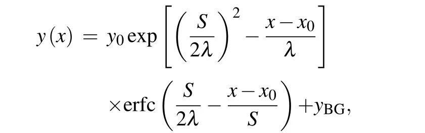
where erfc is the Gauss error function,x0andyBGare the separatrix location and background flux,Sis introduced for the radial diffusion. The decay lengthλis mapped to the outer midplane (OMP) to avoid the influence of connection length difference.As shown in Fig.6(a),λjs=5.6 mm on the horizontal target is about twice as that on the vertical target(~2.7 mm).This difference may be due to the corner effect. When the strike point locates on the horizontal target, the target plate reflects impinging particles mostly towards the SOL.As a result, high neutral pressure is achieved near the corner, which significantly reduces localTein Fig. 6(b) and promotenein Fig. 6(d).λqon the horizontal target is also larger compared to the vertical target,as seen in Fig.6(c).
We calculateλjs,λqin several similar discharges withPtotal=3.2 MW,including shots#98313,#98332 in LSN configuration and shot#98338 in DN configuration. It is worthy to mention that the results of probes #12 and #11 are not included due to the following reason: both probes are close to


corner on the vertical target as seen in Fig.1(c),as a result,the obtained distributions have the mixed information in which the SOL side are partly with strike point on the horizontal target,while the rest are with strike point on the vertical target. As shown in Fig.7(a),λjson the horizontal target is nearly twice as that on the vertical target.λqon the horizontal target is also larger compared to the vertical target,as seen in Fig.7(b). The weak corner effect on heat flux is probably due to low electron density or lack of energy dissipation, which still needs more research.
It is worthy to mention that the DN configuration does not narrow the decay length compared to LSN configuration,as seen in Fig. 7, consistent with previous work.[10]Besides,for the vertical target,λjs/λq≈1.3, which shows that the divertor heat flux is mainly dominated by the divertor particle flux.[10,11]However,the ratio is much larger for the horizontal target,i.e.~2,which may be due to the corner effect.
3.4. Divertor plasma behavior in the Ohmic discharges
The Ohmic discharges are also conducted with strike point sweeping,i.e., shots #98895 and #98896. In the two shots,nel≈2×10¹⁹m-3andIp=500 kA, which are similar with the shots mentioned above. Typical divertor plasma distributions are shown in Fig. 8. WithTe,peak~12 eV, the heat flux distribution on the target is mainly dominated by the particle flux.λjs=11.4 mm andλq=10.3 mm are obtained,which are significantly larger compared to the discharges with high RF heating power.
In these Ohmic discharges, the corner effect becomes weak.λjson the horizontal and vertical target is obtained, as shown in Fig.9. And there is no clear difference between the horizontal target and vertical target,which implies that the corner effect is weak. TheTemeasurement is poor in these two shots,and only few probes can provide the heat flux distributions,which are almost the same as Fig.8(c).

3.5. Discussion on the decay length

4. Summary
In this paper,divertor plasma behavior through sweeping strike point recently conducted on EAST,which has upgraded the lower divertor with closed corner structure. As the strike point sweeps from the horizontal target and vertical target,the peak surface temperature of the divertor target measured by IR camera moves with strike point. And the local surface temperature successfully cools down as the strike point moves away,which indicate that the heat load is mitigated by sweeping strike point.
To study the behavior of particle flux and heat flux on the divertor target,a method based on sweeping strike point is used to avoid the effect of probe tip damage.λjson the horizontal target is almost twice as that on the vertical target,andTeis also lower for the horizontal target. These differences may be due to the corner effect, which is one of the design thoughts of the new divertor with closed corner. In the Ohmic discharges,the corner effect seems weak andλjs,λqare much larger than the discharges with high RF heating power. The underlying mechanism may be that higher edgeTecan narrow theλjs,λq,consistent with the simulation results.[12]
Acknowledgments
The authors would like to acknowledge collaboration of the EAST team. Project supported by the National Key Research and Development Program of China(Grant No. 2017YFE0301300), the National Natural Science Foundation of China (Grant Nos. 12005257, 12005004,11905143, and 11922513), the Fund from the Institute of Energy, Hefei Comprehensive National Science Center(Grant No. GXXT-2020-004), the CASHIPS Director’s Fund(Grant Nos. BJPY2019A01 and YZJJ2020QN13), the Special Research Assistant Funding of CAS and China Postdoctoral Science Foundation (Grant No. 2020M671913),and Anhui Provincial Natural Science Foundation (Grant No.2008085QA38).
猜你喜欢
Plasma Science and Technology(2022年2期)2022-03-10
当代工人(2019年23期)2019-12-30
东西南北(2019年19期)2019-12-12
故事会(2019年6期)2019-03-27
飞魔幻A(2019年11期)2019-02-06
商周刊(2018年16期)2018-08-14
中国(韩文)(2018年1期)2018-01-17
理科考试研究·高中(2017年7期)2017-11-04
做人与处世(2017年15期)2017-09-03
小雪花·初中高分作文(2017年6期)2017-06-29

- Chinese Physics B的其它文章
- Ergodic stationary distribution of a stochastic rumor propagation model with general incidence function
- Most probable transition paths in eutrophicated lake ecosystem under Gaussian white noise and periodic force
- Local sum uncertainty relations for angular momentum operators of bipartite permutation symmetric systems
- Quantum algorithm for neighborhood preserving embedding
- Vortex chains induced by anisotropic spin–orbit coupling and magnetic field in spin-2 Bose–Einstein condensates
- Short-wave infrared continuous-variable quantum key distribution over satellite-to-submarine channels