
Photo-assisted Rechargeable Metal Batteries for Energy Conversion and Storage
2022-07-04 09:14NanfuYanandXuepingGao
Energy & Environmental Materials 2022年2期
Nanfu Yan* , and Xueping Gao*
1. Introduction
Exploring for alternative renewable energy sources is an effective and feasible way to fulfill the increasing energy demand.Solar energy is recognized as an efficient and economical alternative energy source owing to its advantages of green,low cost,and abundant supply.Although the photovoltaic cells are considered as a successful commercial approach for utilizing solar energy, how to store the electrical energy converted from solar energy in an efficient and economic manner is still the great challenge for scientific community.[1,2]Therefore, it is necessary to develop a high-energy device to meet the requirements of efficient utilization of solar energy in response to the concept of sustainable development.[3]
In recent years, high-performance photovoltaics (PV) or solar cells are widely reported with constantly breaking world records on the power conversion efficiency (PCE). For instance,perovskites solar cells can achieve high PCE of over 20% in the laboratory through optimizing the fabrication process and the composition of perovskite active layer, and improving interfaces.[4,5]Moreover, the high PCE of about 18% can be obtained for organic solar cells after years of effort.[6–8]Therefore, the rapid development of photovoltaics technology also brings a new opportunity for fabricating solar energy conversion and storage devices.Recently, several prototypes of solar energy conversion and storage devices are proposed to overcome the disadvantage of the intermittent nature of solar light, such as solar rechargeable batteries,[9–11]solar rechargeable redox flow batteries,[12–14]and solar rechargeable capacitors.[15–18]Such integrated devices combine electrochemical energy storage systems with photovoltaic technology to achieve photocharging with or without external electrical bias.[19–22]Among all the devices,metal-based photo-assisted rechargeable batteries have attracted much attention owing to the high energy storage with rechargeable metal batteries.For instance,metal Li has the highest specific capacity(3860 mAh g−1)and lowest working potential(−3.04 V), making metal Li-based batteries becoming one of the best choices for solar energy storage. Correspondingly, lithium–sulfur battery(Li-S)and lithium–oxygen battery(Li-O2)are the most representative high energy density batteries.[23]In addition, metal Zn-based rechargeable batteries have also attracted great interests based on their advantages of excellent safety performance,earth-abundance,and environmental friendliness.[24,25]It is believed that the combination of high energy density metal batteries and photovoltaics technology would bring new development opportunities for the efficient utilization of solar energy.
In this review, the working principle of photo-assisted rechargeable metal batteries is briefly introduced. In particular, the recent advances of the metal-based rechargeable batteries with high energy density for designing solar energy harvesting and storage devices are summarized with a focus on energy efficiency(ŋ),including metal lithium batteries,metal sodium batteries, and metal zinc batteries. Figure 1 shows the variation of the charge voltage and energy efficiency (ŋ) of various photo-assisted rechargeable metal batteries under light and dark conditions. The comprehensive classification and characteristics of photo-assisted rechargeable batteries are presented in Table 1. Finally, the challenge and outlook are proposed for photo-assisted rechargeable metal batteries as a competitive and innovative strategy for energy conversion and storage.
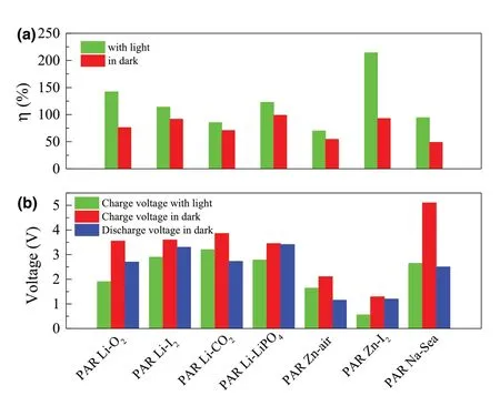
Figure 1. a) The energy efficiencies of different types of the photo-assisted rechargeable metal batteries with or without light. b) Voltages of different types of the photo-assisted rechargeable metal batteries with or without light. Photo-assisted rechargeable Li-O2 battery (PAR Li-O2),[26] photoassisted rechargeable Li-I2 battery (PAR Li-I2),[27] photo-assisted rechargeable Li-CO2 battery (PAR Li-CO2),[28] photo-assisted rechargeable Li-LiFePO4 battery (PAR Li-LiFePO4),[29] photo-assisted rechargeable Zn-air battery (PAR Zn-air),[30] photo-assisted rechargeable Zn-I2 battery (PAR Zn-I2),[31] and photo-assisted rechargeable Na-Seawater battery (PAR Na-Sea).[32]
2. Working Principle of the Photo-assisted Rechargeable Metal Batteries
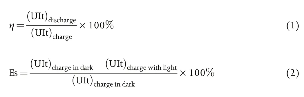
A single cell of photo-assisted rechargeable metal batteries is an integrated device for solar energy harvesting, conversion, and storage. In such device, a photo-assisted charge electrode is introduced into a rechargeable metal battery in order to utilize the excessive and renewable solar energy for photo-assisted charging.The schematic diagram of photo-assisted rechargeable metal battery structure and working principle is shown in Figure 2.The photo-assisted charging and discharging processes of the integrated device are basically similar to the working principle of an individual rechargeable metal battery. Where in this case, the only distinctive feature that differentiating the integrated device from an ordinary rechargeable metal battery is the utilization of solar light to achieve photo-charging with or without external electrical bias.To evaluate the working features and advantages of photo-assisted rechargeable metal batteries, the energy efficiency (η) and energy saving (ES) are presented as the key parameters in this review, which can be obtained from following formula:

Nanfu Yan is Research Assistant in Institute of Applied Chemistry, Jiangxi Academy of Sciences. He received his PhD in 2014 from the college of chemistry, Nankai University.He has focused his research on developing new materials for energy storage technology,with a special interest in solar rechargeable batteries.

Xueping Gao is Professor in Institute of New Energy Material Chemistry, Nankai University of China. He received his doctorate at Department of Chemistry from Nankai University in 1995. He used to work as a visiting research fellow at Kogakuin University in Japan from 1997 to 1999. Currently, his main research is focused on energy storage materials for power sources, including Li-S battery, Li-ion batteries, and solar rechargeable batteries.
The configurations of photo-assisted rechargeable metal batteries can be classified into two types based on different mechanisms.The first configuration of photo-assisted rechargeable metal batteries is composed of a metal anode, a semiconductor, a redox shuttle,and a cathode, as schemed in Figure 2a. Taking dye-sensitized TiO2photo-assisted charge electrode as example, during photo-assisted charge process, as shown in Figure 2b, the photo-generated electrons from excited dye molecules are injected into the conduction band (CB) of the TiO2semiconductor. Then, the oxidized dye molecules are regenerated by receiving electrons from the reduced form of the redox mediator (Sred), which then becomes the oxidized form (Sox) and transports to the cathode. The Soxis reduced back to Sredby oxidizing the reduction state cathode (Cred) into the oxidation state cathode (Cox). Meanwhile, the electrons transport to the metal anode for reducing metal ion (M+) to form metallic anode (M) with the aid of external electrical bias. During discharge process, the metal anode is oxidized into metal ion (M+)and the cathode Coxis reduced into Cred. Finally, the battery returns to the initial state. There are no differences on the electrochemical discharge and charge processes of the photo-assisted rechargeable metal batteries as compared with the conventional rechargeable metal batteries.
The second configuration of photo-assisted rechargeable metal batteries is composed of a metal anode, a separator, and a bi-functional electrode, which consists of a cathode and semiconductor, as indicated in Figure 2c. These kind of photo-assisted rechargeable metal batteries have a simple battery structure with two electrodes that is similar to the conventional rechargeable metal batteries. The working mechanism of photo-assisted rechargeable metal batteries is schematically illustrated in Figure 2d. During photo-assisted charge process, electrons and holes are generated as excited by light on the semiconductor. The holes canoxidize reduction state cathode(Cred)into oxidation state cathode(Cox)due to the higher potential of the valence band(VB)of semiconductor.On the other hand, the photo-generated electrons can reduce M+to metallic M at the anode with the aid of external electrical bias. During discharge process,the metal anode is oxidized into metal ion(M+)and the cathode Coxis reduced into Cred. Finally, the working state of photo-assisted rechargeable metal batteries is backed to the initial state.It is clear that the charge voltage of the external electrical bias can be determined by the potential difference between the M/M+couple and CB of the semiconductor, which can be even lower than the equilibrium potential of rechargeable metal batteries.
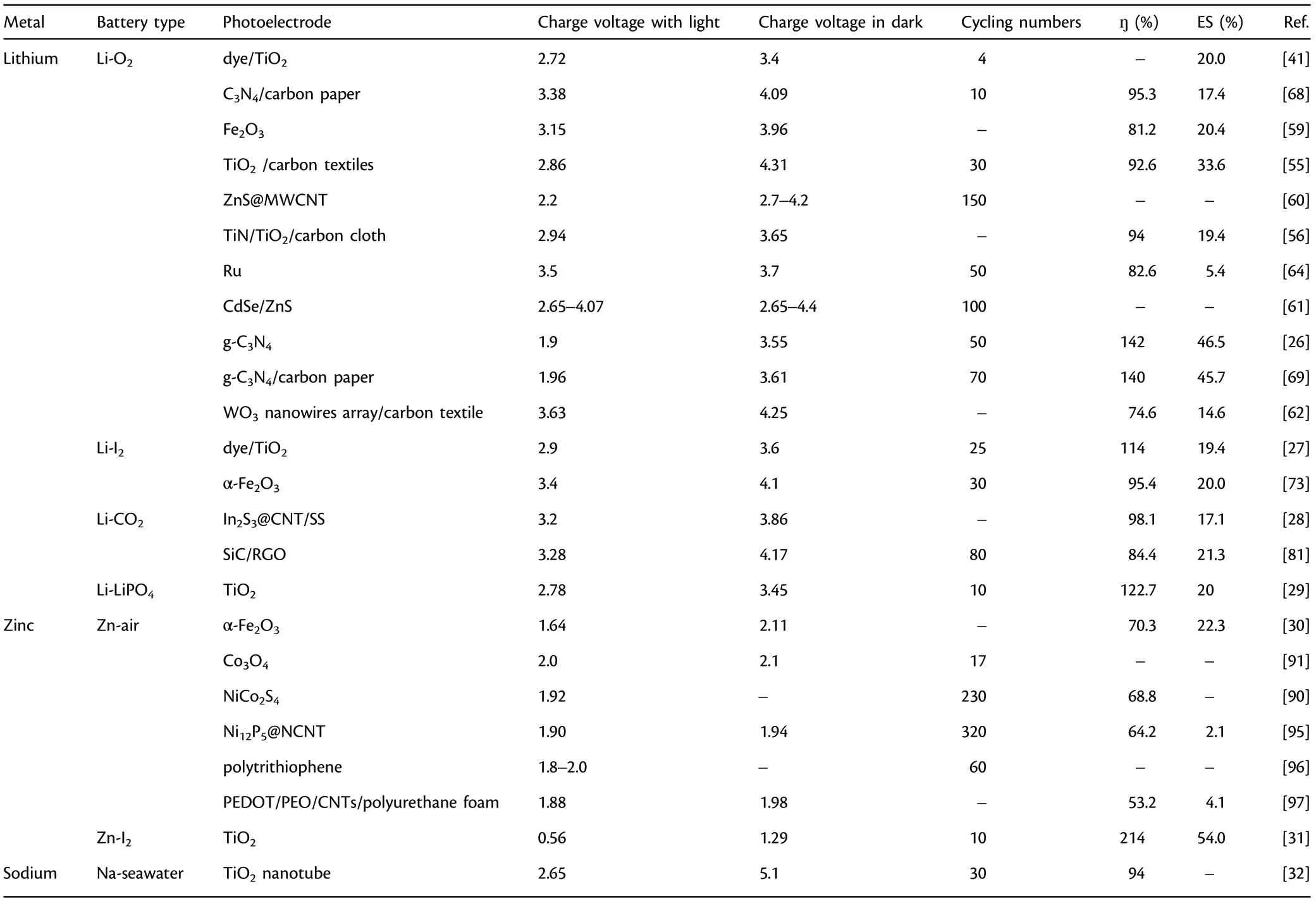
Table 1. Classification and characteristics of photo-assisted rechargeable metal batteries.
Therefore,based on two working mechanisms as shown above,the cathode can be oxidized partially with the aid of the semiconductor in the presence of light.It is shown clearly in Figure 1a that all the as-fabricated rechargeable metal batteries present improved energy efficiency with the aid of light. Moreover, the charging voltages of batteries are significantly reduced with the aid of light (Figure 1b). As shown on the first type of working mechanisms in Figure 1 and Table 1, the photo-assisted rechargeable metal batteries with three electrodes exhibit higher energy efficiency and energy savings. For instance, the as-fabricated photo-assisted rechargeable Li-O2battery based on I−ion redox mediator and a g-C3N4photocatalyst achieves an energy savings of about 46.5% with the aid of light.[26]A photo-assisted rechargeable Zn-I2battery shows a high energy efficiency of about 214%.[31]As indicated in Figure 1b,the low charge voltage of 1.9 V is also obtained for photo-assisted rechargeable Li-O2battery under illumination,[26]while the photo-assisted rechargeable Zn-I2battery shows the ultralow charge voltage of 0.56 V with the aid of light.[31]Although the energy efficiency based on the second type of working mechanisms is slightly less, the photo-assisted rechargeable metal batteries have a simple two electrode structure similar to the conventional rechargeable metal batteries,which would make it more valuable for practical application.
3. Photo-assisted Rechargeable Lithium Metal Batteries
Metal lithium(Li)is regarded as an ideal anode material for rechargeable lithium metal batteries owing to its high theoretical capacity(3860 mAh g−1) and low potential (−3.04 V versus SHE), making metal lithium the ultimate choice for constructing high-energy density batteries.[33–35]For instance, Li-S (2600 Wh kg−1) and Li-O2(3500 Wh kg−1) batteries with lithium metal as anode are intensively investigated as high-energy batteries for next generation energy storage application.[23]Furthermore,if metal lithium is directly used as anode to replace the graphite anode,the energy density of the rechargeable lithium batteries can be enhanced dramatically. The perfect combination of lithium metal batteries and photovoltaics technology is considered to be a new development opportunity for the efficient utilization of solar energy.
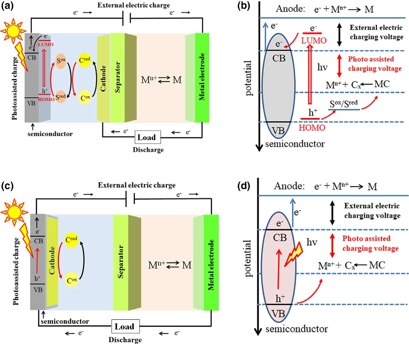
Figure 2. Schematic diagram of the photo-assisted rechargeable metal battery architecture and working principle. a) The battery architecture with three electrodes. b) The working principle of battery with three electrodes. c) The battery architecture with two electrodes. d) The working principle of battery with two electrodes. M: metal anode, C: cathode, S: redox mediator, Cred: reduction state cathode, Cox:oxidation state cathode, Sred: reduction state mediator, and Sox: oxidation state mediator.
3.1. Photo-assisted Rechargeable Li-O2 Battery
Li-O2battery is considered to be a promising energy storage technique owing to the high theoretical energy density based on the battery reaction of 2Li + O2⇌Li2O2.[36–38]However, the intrinsic high overpotential during the Li2O2formation and oxidation processes hinders the development of high-performance Li-O2battery.[39,40]Although the optimization of electrolyte and design of highly efficient catalyst are introduced to address the overpotential issue, exploring new reaction pathways to construct high-performance Li-O2battery remains a challenge.
Recently, a kind of photo-assisted rechargeable Li-O2battery has been proposed by introducing a redox shuttle to couple a photoelectrode with the oxygen electrode for using light energy to solve the overpotential problem in Li-O2battery. A photo-assisted rechargeable Li-O2battery is first designed by introducing a typical redox shuttle(triiodide/iodide) into the electrolyte to couple a dye-sensitized TiO2electrode with the oxygen electrode(Figure 3).[41]It is shown in Figure 3 that the as-fabricated Li-O2battery with Li-I in the electrolyte exhibits a lower voltage plateau at about 2.72 V at the current density of 0.016 mA cm−2under illumination, as compared to the battery with high charge voltage quickly climbing up to about 3.4 V without illumination. The asfabricated device could be charged with a“negative” overpotential with the aid of I3−/I−redox shuttle in the presence of light,which is otherwise thermodynamically impossible(2.96V, O2/Li2O2). As calculated, the photoassisted rechargeable Li-O2battery could achieve energy savings of about 20% with the aid of light.The desired battery performance is ascribed to the extra photo-assisted charge voltage generated from the TiO2photoelectrode,which may compensate the battery’s charging voltage under illumination.Such work provides an effective and generic solution to face problems of low energy efficiency and side reactions for constructing Li-O2battery.Furthermore,when I−ion redox mediator coupled with a g-C3N4photocatalyst is used to design photo-assisted rechargeable Li-O2battery, the as-fabricated device exhibits a lower charging voltage of about 1.9 V under illumination,which is almost equal to the theoretical energy difference (1.7 V) between the CB of g-C3N4and Li/Li+couple potential.[26]In contrast, the device without g-C3N4photocatalyst presents a higher charging voltage of 3.55 V.It is noted that the charging voltage of Li-O2battery (1.9 V) is much lower than the discharging voltage (2.7 V), which delivers an energy efficiency of 142%. As calculated, the as-fabricated Li-O2battery could achieve an energy savings of about 46.5% with the aid of light.Especially, the photo-assisted rechargeable Li-O2battery exhibits excellent cyclic stability under illumination, which delivers a charging voltage of 2.2 V after 50 cycles at 0.01 mA cm−2without noticeable performance decay.
Obviously, the as-fabricated photo-assisted rechargeable Li-O2battery with a redox shuttle exhibits desired performance, especially achieving a lower charging voltage with the aid of light.However,the device also has some inherent defects, such as internal shuttle phenomenon caused by the reduction of redox mediator on the metal electrode, which would decrease the utilization of active mass.[42,43]To make matters worse, the high concentration of redox mediators could also cause undesirable side reactions product,such as LiOH,which has a negative impact on the reversibility of the battery reaction.[44,45]
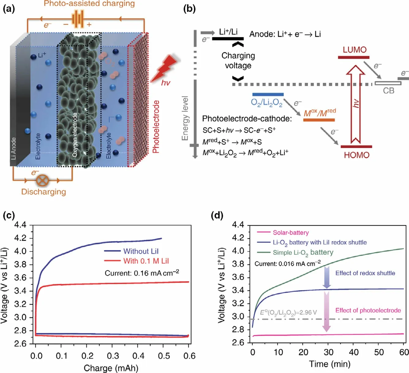
Figure 3. The photo-assisted rechargeable Li-O2 battery a) The schematic diagram and battery structure.b) The energy diagram of a solar battery which integrates a dye-sensitized semiconductor photoelectrode. (“SC” stands for semiconductor and “S” stands for sensitizer). c) The first-cycle discharge–charge curve of the Li-O2 battery with and without Li-I redox shuttle. d) The charging curves of a simple Li-O2 battery, the Li-O2 battery with Li-I redox shuttle, and the solar battery at a current density of 0.016 mA cm−2. Reproduced with permission from ref.[41], Copyright 2014, Springer Nature.
Meanwhile,the photo-assisted rechargeable Li-O2battery can be also constructed by directly using semiconductor electrode without redox shuttle. In general, the basic requirement for the photo-assisted rechargeable Li-O2battery is that the CB potential of the semiconductors should be as low as possible to reduce the charge voltage. Meanwhile,the VB potential of the semiconductors should be more positive to oxidize Li2O2into Li+and O2.It is well-known that titanium dioxide is widely used in numerous fields, such as photocatalytic degradation and splitting,[46,47]photovoltaic cells,[48,49]electrochromic devices,[50,51]hydrogen storage,[52]and sensing instruments,[53]owing to its natural abundance, cost-effectiveness, and unique physicochemical properties.Particularly,TiO2has a low CB potential of 2.6V,which makes it suitable for constructing the photo-assisted rechargeable Li-O2battery.[54]TiO2and their composites,such as defective rutile TiO2,[55]TiN/TiO2/carbon cloth (TT@CC),[56]Au/TiO2nanotube,[57]and TiO2-Fe2O3,[58]are introduced to construct photo-assisted rechargeable Li-O2battery to reduce the high overpotentials. For example, defective rutile TiO2nanorod arrays on carbon textiles(TiO2/CT)can be used as both air cathode and photoelectrode to construct photo-assisted rechargeable Li-O2battery.[55]The TiO2/CT-based battery system presents a lower charging voltage of about 2.86 V (discharge voltage 2.65V) in the first cycle under illumination, as compared to the high charge voltage of 4.31 V in the dark. In particular, the TiO2/CT-based Li-O2battery delivers an energy saving of about 33.6%.It is confirmed that TiO2is more defective under light illumination,and the generated oxygen vacancies can further promote the migration of electrons and Li-ions,leading to the improved ORR performance.In addition,a flexible photo-assisted rechargeable Li-O2battery can be also designed based on a flexible TiN/TiO2/carbon cloth(TT@CC).[56]The assembled flexible Li-O2battery exhibits a charge mid-point voltage of 2.94 V under illumination, much lower than that of 3.65 V in the dark due to the electron–hole pair generated on the surface of excited TT@CC electrode under light illumination.Moreover,under illumination,the flexible Li-O2battery shows a good energy efficiency of about 94% and energy savings of about 19.4%. Therefore, TiO2-based semiconductors can effectively reduce the charge voltage in the presence of light, but the CB potential of TiO2is as high as 2.6 V,limiting the room for further improvement of the photo-assisted rechargeable Li-O2battery.
Besides, metal, metal oxides, metal sulfides, and their composites can be also used as photoelectode in photo-assisted rechargeableLi-O2battery,including ZnS@MWCNT,[60]CdSe/ZnS Dots with carbon nanotube (CdSe/ZnS QD@CNT),[61]WO3nanowires array/carbon textile,[62]WO3/g-C3N4,[63]α-Fe2O3nanorods, and BiVO4nanoplates.[59]For example, the charging voltage of the as-fabricated photoassisted Li-O2battery with CdSe/ZnS QD@CNT photoelectode is started at 2.65 V and ended at 4.07 V in the first cycle under light illumination.[61]As a comparison, the charging voltage of the normal Li-O2battery is ended at 4.4 V without light illumination. It means that CdSe/ZnS QD@CNT can effectively decrease overpotential by photoexcited electron–hole pairs for oxidation of Li2O2, leading to a long-term operational stability over 100 cycles. By introducing a monoclinic WO3nanowires array/carbon textile (WO3NW/CT) photocatalyst into the air cathode,[62]the charge and discharge voltages of the photo-assisted Li-O2battery are 3.63 and 2.71 V in the first cycle in the presence of light, superior to the performance of the normal Li-O2battery with the charge and discharge voltages of 4.25 and 2.25 V without light. Moreover, under illumination, the Li-O2battery with the WO3NW/CT photocatalyst present a good energy efficiency of about 74.6% and energy savings of about 14.6%. In particularly, the charging voltage can still maintain at 3.55 V even after 100 cycles, much lower than that of the dark state (4.4 V). Two typical semiconductor α-Fe2O3nanorods and BiVO4nanoplates are also used in air electrode to design a photo-assisted rechargeable Li-O2battery (Figure 4).[59]As shown in Figure 4b and Figure 4c, α-Fe2O3-based Li-O2battery exhibits a superior long time stability than BiVO4-based Li-O2battery due to the poor natural stability of BiVO4in alkaline electrolyte under illumination. Specifically, the low charge voltage is about 3.15 V for the α-Fe2O3-based Li-O2battery with light, lower than that of 3.96 V of the Li-O2battery in the dark. In the meantime,the high energy efficiency of 81.2% and energy savings of about 20.4% are obtained for the photo-assisted rechargeable device under illumination. It is confirmed that most n-type semiconductors used in PEC water oxidation would have a positive impact on the charge process in Li-O2battery under light illumination.
Moreover,an all-solid-state photo-assisted rechargeable Li-O2battery is proposed recently by using a self-assembly of hybrid Ru nanostructures to utilize light energy.[64]The fabricated all-solid-state Li-O2battery achieves a high discharge of 3600 mAh g−1at a discharge current density of 400 mA g−1at −73 °C(Xe-lamp irradiation).Particularly,a recorded cycle lifespan with a capacity limitation of 1000 mAh g−1is obtained at discharge current density of 400 mA g−1at −73 °C. It is also demonstrated that the grain and interface impedance in all-solidstate Li-O2battery are effectively reduced from about 105Ω cm2to about 103Ω cm2even at −73 °C under solar light irradiation, much lower than that of the normal battery at room temperature. Therefore,the solid state is ideal strategy for designing high energy density Li-O2battery under extreme temperature condition.
In addition,metal-free semiconductors-based photo-assisted rechargeable Li-O2battery is also reported.As is known to all,graphitic carbon nitride (g-C3N4) is wily used as photocatalyst and electrocatalyst.[65,66]Especially,g-C3N4possesses a CB potential of only 1.7 V,which is suitable for constructing photo-assisted rechargeable Li-O2battery.[67]A photo-assisted rechargeable device is constructed by using a single active material carbon nitride (C3N4) as a bi-functional photocatalyst.[68]The introduction of C3N4can remarkably reduce the overpotential of the Li-O2battery by employing solar energy to compensate the electric energy during the charging process under illumination.It is revealed that the discharge and charge voltages of the C3N4-based Li-O2battery are 3.22 V and 3.38 V under illumination, respectively, while the discharge and charge voltages are 2.63 V and 4.09 V,respectively,for the conventional Li-O2battery in the dark. Importantly, the energy efficiency of 95.3%and energy savings of about 17.4% are achieved for the photo-assisted rechargeable Li-O2battery under illumination.Furthermore,by employing the g-C3N4-coated carbon paper(g-C3N4-CP)as both oxygen electrode and photoelectrode, the charge voltage is only 1.96 V for the photo-assisted rechargeable Li-O2battery under light illumination,even lower than the normal redox potential of Li2O2/O2(2.96 V).[69]In contrast, the Li-O2battery presents a high charge mid-point voltage of 3.61 V(the voltage at the half-charge capacity)in the absence of light.It means that the charge voltage of the device is almost identical to the theoretical energy difference(1.7 V)between the CB of g-C3N4and Li/Li+couple.In the discharge process,the normal discharge voltage of 2.74 V is still shown for g-C3N4-CP-based photo-assisted rechargeable Li-O2battery.Such improvement on voltage reduction could result in a relatively high energy efficiency of ~140% and energy savings of about 45.7%.Moreover, the photo-assisted rechargeable Li-O2battery shows stable charging voltage of 2.35V and good cyclic stability without noticeable performance decay over 70 cycles(photo-assisted charge and galvanostatic discharge). Thus, the proper design of g-C3N4-CP could bring a promising path for the future development of the photo-assisted rechargeable all-solid-state Li-O2battery.
Clearly, the as-fabricated photo-assisted rechargeable Li-O2battery without redox shuttle shows satisfied performance with a lower charging voltage under the aid of light. Especially, the solar storage device avoid some inherent defects and undesirable side reactions, such as internal shuttle phenomenon caused by the reduction of redox mediator on the metal electrode. Although the photo-assisted rechargeable Li-O2battery with redox shuttle exhibit higher energy efficiency and energy savings, the battery without redox shuttle have a simple two electrode structure similar to the conventional rechargeable metal batteries, which would make it more valuable for practical application.
3.2. Photo-assisted Rechargeable Li-I2 Battery
Li-iodine (Li-I2) battery is composed of Li metal anode and iodine cathode, which present some unique characteristics, such as the high theoretical capacity (211 mAh g−1), high output voltage(~3.05 V),and high power density.[70–72]Especially,the high solubility of I3−/I−couple is suitable for sharing the catholyte,which make the Li-I2battery favorable for constructing photo-assisted rechargeable Li metal batteries to effectively convert and store solar energy. Activated by dye-sensitized solar cells, a photo-assisted rechargeable Li-I2battery can be constructed,which is consisted of Li metal, aqueous I2catholyte, dye-sensitized TiO2photoanode,and Pt electrode (Figure 5).[27]The as-fabricated device exhibits the charge voltage of 2.90 V under illumination (1 sun AM 1.5),lower than that of 3.60 V of the battery under the normal charge mode in the dark.The energy efficiency of about 114%and energy savings of about 19.4% are obtained for the photo-assisted rechargeable Li-I2battery. The satisfied performance is benefited from the photo-assisted charging mechanism.In the photo-assisted charging mode, dye molecules capture light energy to generate electrons and holes, while the photo-generated electrons can jump to the higher energy level (Ef of TiO2) for energy storage. In addition, the photo-assisted charging mechanism can be also successfully verified in the sodium-iodine (Na-I2) battery. Furthermore,this concept is considered to be a universal strategy for designing metal-iodine batteries. Besides, a hematite (α-Fe2O3) is also introduced into photo-assisted rechargeable Li-I2battery, in which α-Fe2O3is worked as photocatalyst.[73]It is indicated from the anodic linear sweep voltammetry test that the photo-assisted charging process can shift the onset oxidation potential of I−to ~3.4 V under light,lower than that of~3.85 V in the absence of light.The as-fabricated Li-I2battery presents a low charge voltage of~3.43 V for I−oxidation at a current rate of 0.075 mA cm−2under light,comparing to that of 4.13 V under the normal condition.It is worth noting that after introducing hematite into Li-I2battery, the high energy efficiency of ~95.4% is observed in the photo-assisted charge process,~20%higher than that in the absence of light.Furthermore,the photo-assisted Li-I2battery exhibits excellent cyclic stability,which can work over 600 h without noticeable performance decay.
3.3. Photo-assisted Rechargeable Li-CO2 Battery
The greenhouse effect caused by the massive emission of CO2gas is a big headache for human society.Surprisingly,CO2can be used as active material in lithium–carbon dioxide (Li-CO2) battery with a high theoretical energy density of 1876 Wh kg−1. Li-CO2battery would be a viable option in utilizing CO2, which offers an environmentally friendly CO2reduction solution.[74,75]Recently, a series of solutions have been introduced to address the overpotential issue.[76–79]Thus,exploring new reaction pathways to construct high-performance Li-CO2battery remains a challenge.
A flexible photo-assisted rechargeable Li-CO2battery is designed by using an In2S3@CNT/SS (ICS) electrode as bi-functional cathode (Figure 6).[28]A working mechanism for accelerating kinetics of CO2reduction and evolution is proposed by using light energy to reduce In3+into In+for"pre-activating"CO2.The fabricated flexible battery presents the low charge voltage of 3.20 V with light,delivering the high energy efficiency of 98.1%. Without light, the high charge voltage of 3.86 V is shown for Li-CO2battery with the low energy efficiency of 70.7%.The excellent battery performance is attributed to the hierarchical porous and free-standing structure of ICS,as well as the key role of electrons/holes generated on ICS under illumination. The working mechanism of the photo-assisted charge and discharge process can be perfectly verified from the experimental results and analysis,providing a universal strategy to transfer greenhouse gases into active material though Li-CO2battery.Besides, some new photocatalysts are also reported for photo-assisted rechargeable Li-CO2battery,such as Cu2O[80]and SiC grown on reduced graphene oxide(SiC/RGO).[81]The Li-CO2battery with SiC/RGO photocatalyst exhibits the high energy efficiency of 84.4%with the high discharge voltage of 2.77 V (theoretical potential 2.80 V) and the low charge voltage of 3.28 V with light.[81]
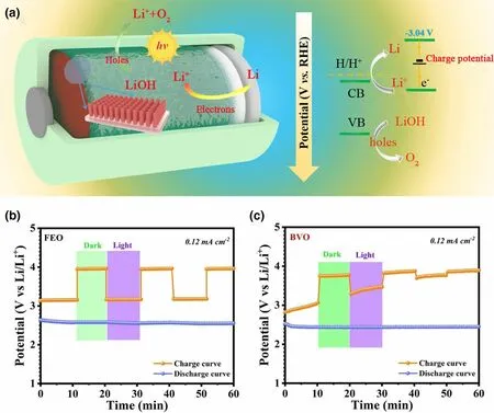
Figure 4. a) The diagram and mechanism of the photo-assisted hybrid Li-O2 battery. b, c) Photoassisted Li-O2 battery using Fe2O3 and BiVO4 as cathode with chopped light illumination. Reproduced with permission from ref.[59]. Copyright 2020, Springer.
3.4. Photo-assisted Rechargeable Li-ion Batteries
Li-ion batteries are more universally used as standard battery technologies.The combination of solar cells and rechargeable Li-ion battery has also attracted the attention of scientists.[82,83]A photo-assisted rechargeable Li-ion battery (LIB) is demonstrated, which is composed of three compartments,the metal lithium anode,LiFePO4cathode,and TiO2electrode.[29]It benefited from the generated photovoltage that the charging voltage of LiFePO4cathode is reduced to 2.78 V under solar light,lower than the discharge voltage of 3.41 V.In the meantime,the photo-assisted rechargeable LIB shows the energy savings of about 20%,as compared to conventional LIB. It is believed that the concept of “photo-assisted charge”could be also realized in LIBs with other cathode materials,such as LiCoO2,LiMnPO4,and LiMn2O4by selecting appropriate redox shuttles.The extra lithium insertion reaction of LiMn2O4spinel to Li2Mn2O4at 3.0 V(vs Li/Li+)is carefully selected as the cathodic process for constructing photo-rechargeable LIB.[84]The as-fabricated photorechargeable LIB presents a high charge density at 2300 C cm−3based on the redox of Mn4+/3+.It is worth mentioning that the as-fabricated photo-rechargeable LIB can achieve an outstanding light-to-charge energy efficiency of 11.5%under the dim light condition.Although,the asfabricated photo-assisted rechargeable LIBs present promising performance based on the voltage evaluation under the aid of light.However,the device is fabricated with a complex threeelectrode structure, making it more difficult for preparation and practical application.
4. Photo-assisted Rechargeable Metal Zinc Batteries
Metal lithium is the most widely studied metal anode for constructing high energy density metal batteries. Metal zinc with the advantages of two electron reaction, abundant resources, and relatively low price is more feasible for constructing high energy metal batteries.[85–87]
4.1. Photo-assisted Rechargeable Zn-air Battery
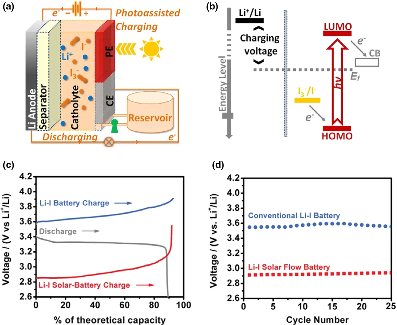
Figure 5. a) Schematic of a Li-I SFB device with the three-electrode configuration; b)Photoelectrochemical half-reactions. Performance comparison between Li-I SFB and conventional Li-I batteries: c) A typical depleted charging and discharging voltage profile; d) The initial charging voltages for 25 cycles. Reproduced with permission from ref.[27]. Copyright 2015, American Chemical Society.
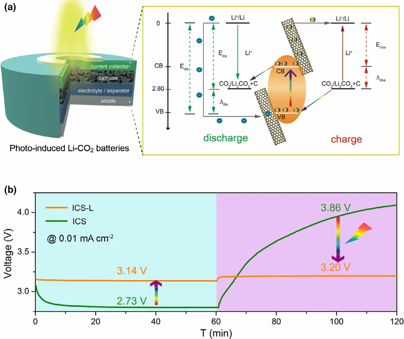
Figure 6. a) Structure and schematic diagram of energy levels for the increased discharge voltage and decreased charge voltage of photo-induced Li-CO2 battery under illumination. b) Discharge and charge curves of the ICS-based Li-CO2 battery with and without illumination at 0.01 mA cm−2. Reproduced with permission from ref.[28] Copyright 2020. Wiley-VCH.
Rechargeable Zn-air battery is an advanced energy storage device with high theoretical energy density (1086 Wh kg−1), which is also a safe and cost effective battery system.In recent years,the battery performance is improved greatly by the optimization of electrolyte and design of highly efficient catalysts.[88,89]The people is still working on exploring new reaction pathways of Zn-air battery to intrinsically reduce the high overpotential during the charge/discharge process,and solve the sluggish reaction dynamics for both oxygen evolution reaction (OER) and oxygen reduction reaction (ORR).Inspired by the strategy of building photo-assisted rechargeable metal Li batteries,a photo-assisted rechargeable Zn-air battery is also proposed to reduce the high overpotential by introducing photocatalysts, which could further adjust the reaction pathways for improving Zn-air battery performance. For instance, a photo-assisted rechargeable Zn-air battery is designed by using two typical semiconductor α-Fe2O3or BiVO4as air electrode(Figure 7).[30]The effect of the band structure and photoelectrochemical stability of the α-Fe2O3or BiVO4air electrode on the charging performance of the photo-assisted zinc–air battery is studied in detail.It is demonstrated that the photo-assisted zinc–air battery with BiVO4photocatalyst can work with an extremely low charge voltage of about 1.20 V at the current density of 0.1 mA cm−2under illumination,delivering the energy saving of about 38.8%.With the help of α-Fe2O3photocatalyst, the low charge potential of about 1.43 V at the current density of 0.1 mA cm−2is observed for zinc–air battery under illumination, as compared to that of about 1.97 V in the dark (Figure 7c), showing the energy saving of about 27.4%. At the current density of 0.5 mA cm−2, the high energy efficiency of ~70.3% and energy saving of about 22% are still obtained for the α-Fe2O3-based zinc–air battery. It is demonstrated that choosing semiconductor with more negative CB positions, appropriate VB positions, and high photoelectrochemical stability is effective to address the high over potential issue of zinc–air battery. Besides, metal sulfides, metal oxides,metal phosphides, and their composites can be also used as photoelectode in photo-assisted rechargeable zinc–air battery, including NiCo2S4,[90]Co3O4,[91]CdS/TiO2,[92]ZnS/CdSe/CdS/TiO2,[93]TiO2/carbon papers,[94]and Ni12P5@NCNT.[95]For example, the photo-assisted zinc–air battery with NiCo2S4photoelectode presents a stable cycling performance with the charge and discharge potential plateaus of ~1.92 V and ~1.32 V at a current density of 2 mA cm−2under light illumination,increasing the energy efficiency from 59.2%to 68.8%.[90]Therefore,the strategy of introducing a semiconductor photoelectrode with an optimized CB and VB positions is a promising solution to construct Zn-air battery with high stability and energy efficiency. Furthermore,TiO2grown on carbon papers can be also used to construct photo-assisted rechargeable Zn-air battery for harvesting solar energy.[94]With TiO2cathode,the Zn-air battery achieves the record-low charge voltage of 0.59 V at 0.1 mA cm−2, lower by 1.29 V than that(1.88 V) of the state-of-the-art battery with Pt/C + RuO2electrocatalyst. Besides, when Ni12P5@NCNT is introduced into Zn-air battery, the improvement on the charge/discharge voltages and energy efficiency is also achieved under illumination,[95]due to the good photocatalytic activity of bi-functional Ni12P5@NCNT air cathode. In addition to inorganic semiconductors, polymer semiconductors are also investigated for the photo-assisted rechargeable Zn-air battery.Typically, a polytrithiophene (pTTh) is designed to enhance the electrocatalyst activity with the aid of light energy by reducing the energy barrier toward OER/ORR processes at the air electrode for zincair battery.[96]The pTTh-based zinc–air battery exhibits the high discharge voltage of 1.78 V at 0.1 mA cm−2under illumination without decay for 64 h during the discharge and charge cycle. In particular, the energy density of the battery can be raised by 29.0% under illumination compared to that of the conventional Pt/C-based Zn-air battery. Furthermore, multi-scale PEDOTPEO-carbon nanotube-polyurethane foam is also used to assemble a self-standing air electrode for designing a smart rechargeable Zn-air battery.[97]As expected, the zinc–air battery shows the advantage on low charge voltage of 1.88 V and energy efficiency of 53.2% under illumination.
4.2. Photo-assisted Rechargeable Zn-I2 Battery
A photo-assisted rechargeable Zn-I2battery (ZIB) is demonstrated by using TiO2electrode (TNTs) as photocatalyst to improve the battery performance (Figure 8).[31]As shown in Figure 8d, the ultralow charge voltage of 0.56 V at the current density of 0.01 mA cm−2is achieved for the constructed Zn-I2battery under illumination, much lower than the charge voltage of 1.29 V in the dark.The results indicate that the high energy saving of about 54%is obtained for the photo-assisted rechargeable Zn-I2battery. Besides, the fabricated Zn-I2battery can still deliver a low charging voltage of 0.65 V after 10 cycles, suggesting the good stability of the TiO2photoelectrode. The concept of using earth-abundant metal and low-cost redox couple to construct photo-assisted rechargeable Zn-I2battery may break new grounds for design and fabrication of highly efficient solar energy conversion and storage devices.
Indeed, the as-fabricated photo-assisted rechargeable Zn-I2battery(ZIB)can effectively reduce the charge voltage and demonstrate a highest energy saving under illumination. However, the high CB potential of TiO2photoelectrode (2.6 V) limits the room for further improvement. Because the utilization of visible light is low for the TiO2photoanode, the battery just can perform well must under UV light.Therefore, the construction of high-performance photo-assisted rechargeable Zn-I2battery requires developing suitable photoelectrodes,which can efficiently use visible light.
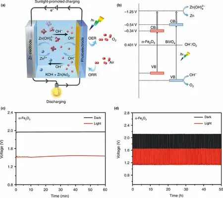
Figure 7. a) Schematic sunlight-promoted charge and discharge processes of the sunlight-promoted zinc–air battery. b) The proposed mechanism of the sunlight-promoted charging process under solar light illumination. c)The charging curves of a zinc–air battery in the dark and under illumination with α-Fe2O3 air photoelectrode at a current density of 0.1 mA cm−2. d) Cycling performance of sunlight-promoted rechargeable zinc–air battery in the dark and under illumination with and α-Fe2O3 air photoelectrode at a current density of 0.5 mA cm−2. Reproduced with permission from ref.[30]. Copyright 2019,Springer Nature.
5. Photo-assisted Rechargeable Metal Sodium Batteries
The metal sodium has the advantage of abundant,wide distribution in the earth’s crust and relatively low price. More importantly, metal sodium presents similar physicochemical properties to lithium.[98,99]These attractive merits of metal sodium make it suitable for applications in fabricating devices for efficient solar energy conversion and storage.A photo-assisted rechargeable metal sodium battery is designed by combining TiO2nanotube array photoelectrode (TNTs) into the seawater battery(Figure 9).[32]It is revealed that the fabricated battery with TNTs presents the high charge voltage of about 5.1 V in the dark.Under illumination, the charge voltage of the battery is decreased sharply to~2.65 V, achieving a relatively high energy efficiency of ~94% for the solar seawater battery.As a comparison,heated carbon felt(HCF)is used as photocatalyst,the battery shows no response toward the light during the charge process. Correspondingly, the high charge voltage of about 3.8 V and relatively low energy efficiency of~76%at 0.015 mA cm−2are observed for the battery.Clearly,the energy efficiency of the sodium seawater battery with TNTs photocatalyst can be effectively improved with the aid of light.Metal sodium batteries have many natural advantages,especially seawater-based sodium batteries.There is no doubt that the as-fabricated photo-assisted rechargeable metal sodium battery has achieved energy savings with aid of light,but there is still much room for improvement.For example,the structure of the battery needs to be simplified,and the cycle life of the battery needs to be improved.Meanwhile,more types of photo-assisted rechargeable metal sodium batteries need to be explored and developed.
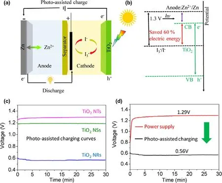
Figure 8. a) Schematic illustration of a photo-assisted chargeable ZIB with a three-electrodes system. b)The energy diagram of the photo-assisted ZIB.c)The charge curves of photo-assisted chargeable aqueous ZIB at a current of 0.01 mA cm−2 containing TiO2 NTs, TiO2 NSs, and TiO2 NRs as photoelectrode,respectively.d)The charge and the discharge curves of the ZIB using TiO2 NRs as the photoelectrode(black lines for power supply charge and discharge process at 0.01 mA cm−2;red lines for photo-assisted charge;and galvanostatically discharge at 0.01 mA cm−2). Reproduced with permission from ref.[31]. Copyright 2019.Wiley-VCH.
6. Conclusion and Perspectives
In conclusion, a brief overview of photo-assisted rechargeable metal batteries is given in recent years, including the working mechanism,structure design,photo-assisted charging mode,and performance characteristics. There is no doubt that the concept of “photo-assisted charge” is realized in light-weight metal-based rechargeable batteries.The as-fabricated rechargeable metal batteries present desired electrochemical performance. For example, photo-assisted rechargeable Li-O2battery achieves the low charge voltage of 1.9 V and high energy efficiency of 142%under illumination.[26]Photo-assisted rechargeable Zn-I2battery shows the ultralow charge voltage of 0.56 V,and remarkable energy efficiency of 214%.[31]Although great efforts are made to achieve good performance, the design of photo-assisted rechargeable metal batteries with high energy efficiency and long-term stability is still a challenging task, and there are undoubtedly plenty room for improvement.
Firstly, although many photo-assisted rechargeable batteries based on light-weight metal anodes are successfully designed,including metal Li,Na,and Zn,there are still large spaces for exploration of photoassisted rechargeable battery system based on new active materials and new electrode structure.For instance,other metal batteries with K,Ca,Mg,Al,Fe,and alloys anode are also developed rapidly (Table 2). Taking Mg metal batteries as an example, the Mg-O2battery shows high theoretical energy density and discharge voltage, which are comparable to that of Li-O2battery. Al-air battery has also demonstrated great potential owing to its outstanding advantages of high specific capacity of 2980 mAh g−1, low cost, environmentally benign, and geological reserve abundance of Al.[100–103]These attractive merits make them suitable in fabricating photo-assisted rechargeable metal batteries in future, after matching with solar cells.
Secondly,the design and fabrication of more stable and safe photo-assisted rechargeable metal batteries are beneficial for promoting the practical applications. Although the existing photo-assisted rechargeable metal batteries show many potential advantages, there are still some disadvantages to face in future.For example, both lithium and sodium metals are not easy to apply to device products because of highly active reactivity, thus explosiveness. In addition,zinc rechargeable batteries suffer from the poor cycle stability because of the unavoidable formation of zinc hydroxides during longterm operation.Besides,it is well-known that dendrite issues are common for metal anodes in metal-based batteries with liquid electrolytes.At present,the proposed photo-assisted rechargeable batteries are almost fabricated based on organic liquid electrolyte and aqueous solution electrolyte. Therefore, the design and fabrication of quasi solid-state and all-solid-state photo-assisted rechargeable metal batteries with the help of gel electrolyte or solid-state electrolyte would be a new direction.
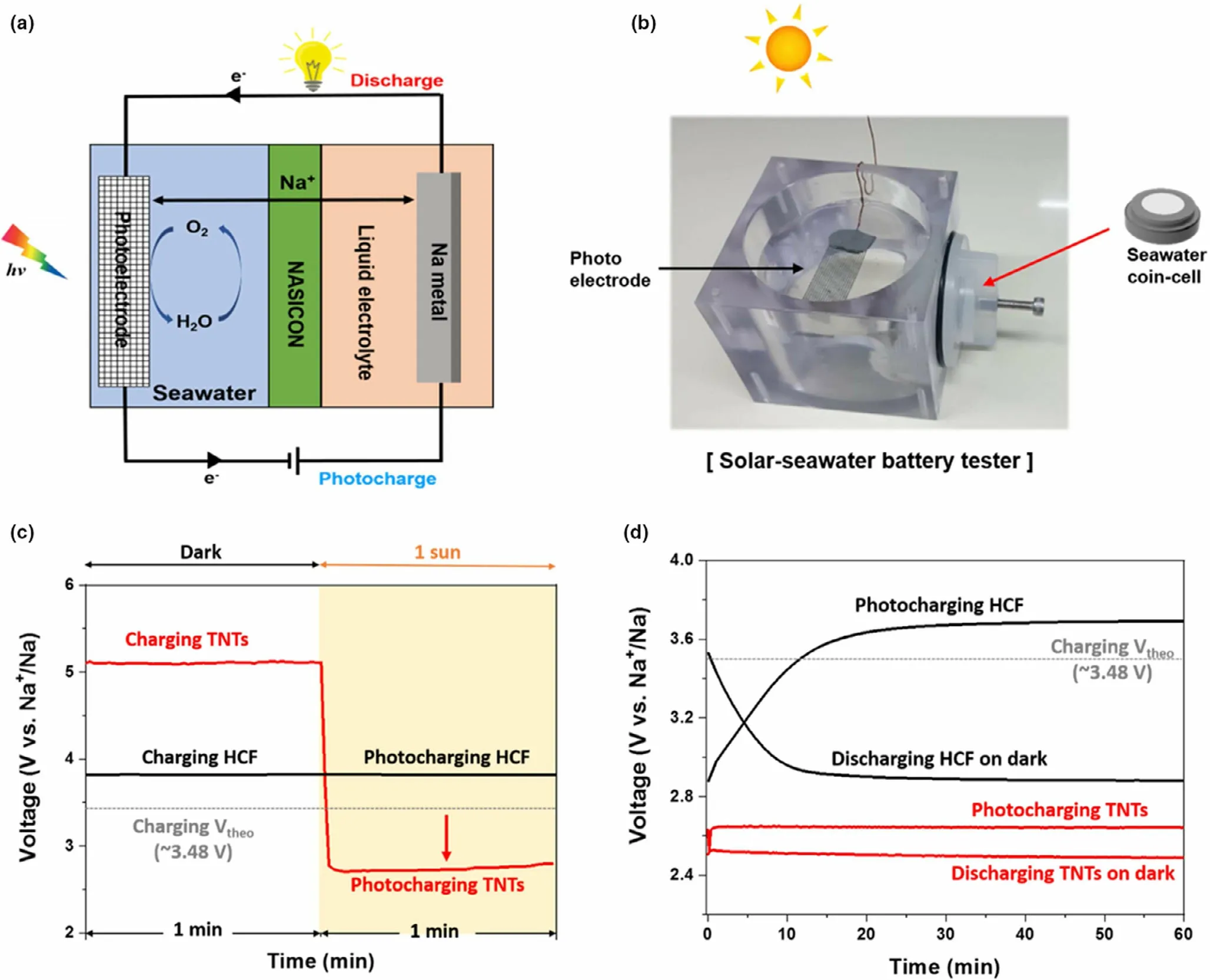
Figure 9. a) Schematic diagram of the cell configuration of the solar seawater battery. b) Digital image of a used solar seawater cell tester. c) Galvanostatic charging (dark and 1 Sun irradiation) at 0.015 mA cm−2 for the TNTs photoanode and HCF cathode, and d) Initial charge and discharge curves for the TNTs photoanode and HCF cathode at 0.015 mA cm−2. Reproduced with permission from ref.[32]. Copyright 2020. Elsevier.
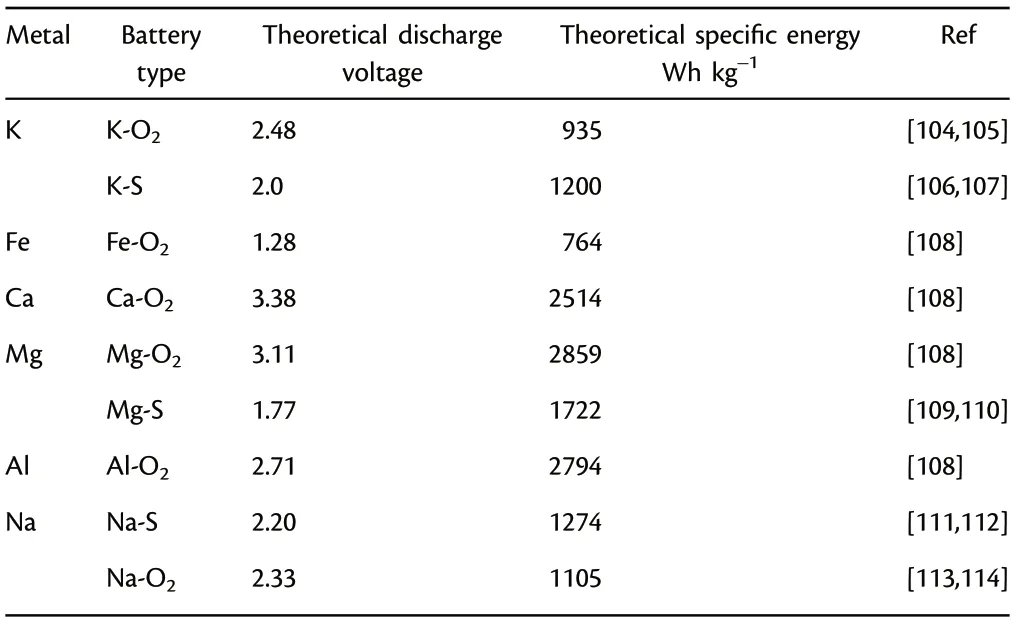
Table 2. Classification of metal batteries for constructing photo-assisted rechargeable batteries in future.
Thirdly, most of the research works of photo-assisted rechargeable batteries have been done under very different experimental conditions;it is difficult to compare the results from published papers.To the best of our knowledge,there is still no test standard for measuring the characteristics of photo-assisted rechargeable batteries, which needs to be established and standardized. Furthermore, some important metrics,such as the light to electrochemical energy conversion efficiencies are not discussed in most of the research works of photo-assisted rechargeable batteries, which need more research works to understand the above deficiencies.
Finally, the development of photo-assisted rechargeable metal batteries is just a middle stage. Solar rechargeable batteries with complete photocharge mode are on the way to new energy conversion and storage. The some successful experiences on working mechanism, active materials, and battery structure of photo-assisted rechargeable metal batteries could be borrowed for fabricating solar rechargeable batteries.
Acknowledgements
Financial supports from National Natural Science Foundation (21875123) of China,and the project of Jiangxi Academy of Sciences(2020-YZD-3)are gratefully acknowledged.
Conflict of Interest
The authors declare no conflict of interest.
Keywords
metal anodes, photo-assisted charge, rechargeable batteries, solar cells
Received: January 15, 2021
Revised: February 3, 2021
Published online: February 8, 2021
[1] J. Rugolo, M. J. Aziz, Energy Environ. Sci. 2012, 5, 7151.
[2] Y. Hou, R. Vidu, P. Stroeve, Ind. Eng. Chem. Res. 2011, 50, 8954.
[3] B. Dunn, H. Kamath, J. M. Tarascon, Science 2011, 334, 928.
[4] K. A. Bush, A. F. Palmstrom, Z. S. J. Yu, M. Boccard, R. Cheacharoen, J.P. Mailoa, D. P. McMeekin, R. L. Z. Hoye, C. D. Bailie, T. Leijtens, I. M.Peters, M. C. Minichetti, N. Rolston, R. Prasanna, S. Sofia, D. Harwood,W. Ma, F. Moghadam, H. J. Snaith, T. Buonassisi, Z. C. Holman, S. F.Bent, M. D. McGehee, Nat. Energy 2017, 2, 7.
[5] P. Caprioglio, C. M. Wolff, O. J. Sandberg, A. Armin, B. Rech, S. Albrecht,D. Neher, M. Stolterfoht, Adv. Energy Mater. 2020, 10, 2000502.
[6] Q. Liu, Y. Jiang, K. Jin, J. Qin, J. Xu, W. Li, J. Xiong, J. Liu, Z. Xiao, K.Sun, S. Yang, X. Zhang, L. Ding, Sci. Bull. 2020, 65, 272.
[7] L. X. Meng, Y. M. Zhang, X. J. Wan, C. X. Li, X. Zhang, Y. B. Wang, X.Ke, Z. Xiao, L. M. Ding, R. X. Xia, H. L. Yip, Y. Cao, Y. S. Chen, Science 2018, 361, 1094.
[8] H. Yao, J. Wang, Y. Xu, S. Zhang, J. Hou, Acc. Chem. Res. 2020, 53, 822.
[9] B. Lei, G.-R. Li, P. Chen, X.-P.Gao, ACS Appl. Energy Mater. 2019, 2, 1000.
[10] P. Liu, H. X. Yang, X. P. Ai, G. R. Li, X. P. Gao, Electrochem. Commun.2012, 16, 69.
[11] N. F. Yan, W. H. Zhang, H. M. Cui, X. J. Feng, Y. W. Liu, J. S. Shi, Sustain Energy Fuels 2018, 2, 353.
[12] L. Cao, M. Skyllas-Kazacos, D.-W. Wang, Adv. Sustain. Syst. 2018, 2,1800031.
[13] P. Liu, Y.-L. Cao, G.-R. Li, X.-P. Gao, X.-P. Ai, H.-X. Yang, Chemsuschem 2013, 6, 802.
[14] N. F. Yan, G. R. Li, X. P. Gao, J. Mater. Chem. A 2013, 1, 7012.
[15] A. Das, S. Deshagani, R. Kumar, M. Deepa, ACS Appl. Mater. Interfaces 2018, 10, 35932.
[16] H. Meng, S. Pang, G. Cui, Chemsuschem 2019, 12, 3431.
[17] C. H. Ng, H. N. Lim, S. Hayase, I. Harrison, A. Pandikumar, N. M.Huang, J. Power Sources 2015, 296, 169.
[18] K. Poonam, A. Sharma, A. Arora, S. K. Tripathi, J. Energy Storage 2019,21, 801.
[19] A. Gurung, Q. Qiao, Joule 2018, 2, 1217.
[20] Q. Li, Y. Liu, S. H. Guo, H. S. Zhou, Nano Today 2017, 16, 46.
[21] D. Schmidt, M. D. Hager, U. S. Schubert, Adv. Energy Mater. 2016, 6,1500369.
[22] Q. Zeng, Y. Lai, L. Jiang, F. Liu, X. Hao, L. Wang, M. A. Green, Adv.Energy Mater. 2020, 10, 1903930.
[23] P. G. Bruce, S. A. Freunberger, L. J. Hardwick, J.-M. Tarascon, Nat.Mater. 2012, 11, 19.
[24] C. Wang, G. Zhu, P. Liu, Q. Chen, ACS Nano 2020, 14, 2404.
[25] F. Wang, O. Borodin, T. Gao, X. Fan, W. Sun, F. Han, A. Faraone, J. A.Dura, K. Xu, C. Wang, Nat. Mater. 2018, 17, 543.
[26] Y. Liu, N. Li, S. Wu, K. Liao, K. Zhu, J. Yi, H. Zhou, Energy Environ. Sci.2015, 8, 2664.
[27] M. Yu, W. D. McCulloch, D. R. Beauchamp, Z. Huang, X. Ren, Y. Wu,J. Am. Chem. Soc. 2015, 137, 8332.
[28] D. Guan, X. Wang, M. Li, F. Li, L. Zheng, X. Huang, J. Xu, Angew. Chem.Int. Ed. 2020, 59, 19518.
[29] Q. Li, N. Li, M. Ishida, H. Zhou, J. Mat. Chem. A 2015, 3, 20903.
[30] X. Liu, Y. Yuan, J. Liu, B. Liu, X. Chen, J. Ding, X. Han, Y. Deng, C.Zhong, W. Hu, Nat. Commun. 2019, 10, 4767.
[31] X. Chang, Z. Xie, Z. Liu, X. Zheng, J. Zheng, X. Li, Energy Storage Mater.2020, 25, 93.
[32] J. Han, S. Lee, C. Youn, J. Lee, Y. Kim, T. Choi, Electrochim. Acta 2020,332, 135443.
[33] X.-B. Cheng, R. Zhang, C.-Z. Zhao, Q. Zhang, Chem. Rev. 2017, 117, 10403.
[34] P. Shi, X.-Q. Zhang, X. Shen, R. Zhang, H. Liu, Q. Zhang, Adv. Mater.Technol. 2020, 5, 1900806.
[35] X. Zhang, Y. Yang, Z. Zhou, Chem. Soc. Rev. 2020, 49, 3040.
[36] J. Lu, L. Li, J.-B. Park, Y.-K. Sun, F. Wu, K. Amine, Chem. Rev. 2014, 114,5611.
[37] D. Wang, X. Mu, P. He, H. Zhou, Mater. Today 2019, 26, 87.
[38] C. Xia, C. Y. Kwok, L. F. Nazar, Science 2018, 361, 777.
[39] Y.-S. Hong, C.-Z. Zhao, Y. Xiao, R. Xu, J.-J. Xu, J.-Q. Huang, Q. Zhang,X. Yu, H. Li, Batteries Supercaps 2019, 2, 638.
[40] H.-D. Lim, B. Lee, Y. Bae, H. Park, Y. Ko, H. Kim, J. Kim, K. Kang, Chem.Soc. Rev. 2017, 46, 2873.
[41] M. Yu, X. Ren, L. Ma, Y. Wu, Nat. Commun. 2014, 5, 5111.
[42] C. K. Lee, Y. J. Park, ACS Appl. Mater. Interfaces 2016, 8, 8561.
[43] T. Zhang, K. Liao, P. He, H. Zhou, Energy Environ. Sci. 2016, 9, 1024.
[44] B. J. Bergner, C. Hofmann, A. Sch¨urmann, D. Schr¨oder, K. Peppler, P. R.Schreiner, J. Janek, Phys. Chem. Chem. Phys. 2015, 17, 31769.
[45] I. Landa-Medrano, M. Olivares-Mar´ın, R. Pinedo, I. Ruiz de Larramendi,T. Rojo, D. Tonti, Electrochem. Commun. 2015, 59, 24.
[46] A. Meng, L. Zhang, B. Cheng, J. Yu, Adv. Mater. 2019, 31, 1807660.
[47] P. Yin, M. Hegde, N. S. Garnet, Y. Tan, P. V. Radovanovic, Nano Lett.2019, 19, 6695.
[48] J. P. Correa-Baena, M. Saliba, T. Buonassisi, M. Gratzel, A. Abate, W.Tress, A. Hagfeldt, Science 2017, 358, 739.
[49] B. Oregan, M. Gratzel, Nature 1991, 353, 737.
[50] J.-Z. Chen, W.-Y. Ko, Y.-C. Yen, P.-H. Chen, K.-J. Lin, ACS Nano 2012, 6,6633.
[51] Y.-Y. Song, Z.-D. Gao, J.-H. Wang, X.-H. Xia, R. Lynch, Adv. Functional Mat. 2011, 21, 1941.
[52] D. V. Bavykin, A. A. Lapkin, P. K. Plucinski, J. M. Friedrich, F. C. Walsh,J. Phys. Chem. B 2005, 109, 19422.
[53] Q. Zheng, B. Zhou, J. Bai, L. Li, Z. Jin, J. Zhang, J. Li, Y. Liu, W. Cai, X.Zhu, Adv. Mat. 2008, 20, 1044.
[54] A. L. Linsebigler, G. Lu, J. T. Yates, Chem. Rev. 1995, 95, 735.
[55] H. Gong, T. Wang, H. Xue, X. Fan, B. Gao, H. Zhang, L. Shi, J. He, J. Ye,Energy Storage Mater. 2018, 13, 49.
[56] X. Yang, X .Feng, X. Jin, M. Shao, B. Yan, J. Yan, Y. Zhang, X. Zhang,Angew. Chem. Int. Ed. 2019, 58, 16411.
[57] S. Tong, C. Luo, J. Li, Z. Mei, M. Wu, A. P. O’Mullane, H. Zhu, Angew.Chem. Int. Ed. 2020, 59, 20909.
[58] M. Li, X. Wang, F. Li, L. Zheng, J. Xu, J. Yu, Adv. Mater. 2020, 32, 1907098.
[59] H. Gong, H. Xue, B. Gao, Y. Li, X. Fan, S. Zhang, T. Wang, J. He, Energy Storage Mater. 2020, 31, 11.
[60] Y. Qiao, Y. Liu, K. Jiang, X. Li, Y. He, Q. Li, S. Wu, H. Zhou, Small Methods 2018, 2, 1700284.
[61] V. Veeramani, Y.-H. Chen, H.-C. Wang, T.-F. Hung, W.-S. Chang, D.-H.Wei, S.-F. Hu, R.-S. Liu, Chem. Eng. J. 2018, 349, 235.
[62] Y. Feng, H. Xue, T. Wang, H. Gong, B. Gao, W. Xia, C. Jiang, J. Li, X.Huang, J. He, ACS Sustain. Chem. Eng. 2019, 7, 5931.
[63] H. Xue, T. Wang, Y. Feng, H. Gong, X. Fan, B. Gao, Y. Kong, C. Jiang, S.Zhang, X. Huang, J. He, Nanoscale 2020, 12, 18742.
[64] H. Song, S. Wang, X. Song, J. Wang, K. Jiang, S. Huang, M. Han, J. Xu,P. He, K. Chen, H. Zhou, Energy Environ. Sci 2020, 13, 1205.
[65] G. Liao, Y. Gong, L. Zhang, H. Gao, G.-J. Yang, B. Fang, Energy Environ.Sci. 2019, 12, 2080.
[66] Y. Xu, M. Kraft, R. Xu, Chem. Soc. Rev. 2016, 45, 3039.
[67] J. Liu, H. Wang, M. Antonietti, Chem. Soc. Rev. 2016, 45, 2308.
[68] Z. Zhu, X. Shi, G. Fan, F. Li, J. Chen, Angew. Chem. Int. Ed. 2019, 58, 19021.
[69] Y. Liu, N. Li, K. Liao, Q. Li, M. Ishida, H. Zhou, J. Mater. Chem. A 2016,4, 12411.
[70] K. Lu, Z. Hu, J. Ma, H. Ma, L. Dai, J. Zhang, Nat. Commun. 2017, 8, 527.
[71] Q. Zhang, Z. Wu, F. Liu, S. Liu, J. Liu, Y. Wang, T. Yan, J. Mater. Chem.A 2017, 5, 15235.
[72] Q. Zhao, Y. Lu, Z. Zhu, Z. Tao, J. Chen, Nano Lett. 2015, 15, 5982.
[73] G. Nikiforidis, K. Tajima, H. R. Byon, ACS Energy Lett. 2016, 1, 806.
[74] B. Liu, Y. Sun, L. Liu, J. Chen, B. Yang, S. Xu, X. Yan, Energy Environ.Sci. 2019, 12, 887.
[75] X. Mu, H. Pan, P. He, H. Zhou, Adv. Mater. 2020, 32, 1903790.
[76] A. Hu, C. Shu, C. Xu, R. Liang, J. Li, R. Zheng, M. Li, J. Long, J. Mater.Chem. A 2019, 7, 21605.
[77] C. Hu, L. Gong, Y. Xiao, Y. Yuan, N. M. Bedford, Z. Xia, L. Ma, T. Wu,Y. Lin, J. W. Connell, R. Shahbazian-Yassar, J. Lu, K. Amine, L. Dai, Adv.Mater. 2020, 32, 1907436.
[78] C. Li, Z. Guo, B. Yang, Y. Liu, Y. Wang, Y. Xia, Angew. Chem. Int. Edi.2017, 56, 9126.
[79] R. Wang, X. Zhang, Y. Cai, Q. Nian, Z. Tao, J. Chen, Nano Res. 2019,12, 2543.
[80] A. Jena, H. C. Hsieh, S. Thoka, S. F. Hu, H. Chang, R. S. Liu, Chemsuschem 2020, 13, 2719.
[81] Z. Li, M.-L. Li, X.-X. Wang, D.-H. Guan, W.-Q. Liu, J.-J. Xu, J. Mater.Chem. A 2020, 8, 14799.
[82] A. Paolella, A. Vijh, A. Guerfi, K. Zaghib, C. Faure, J. Electrochem. Soc 2020, 167, 120545.
[83] A. Paolella, C. Faure, G. Bertoni, S. Marras, A. Guerfi, A. Darwiche, P.Hovington, B. Commarieu, Z. Wang, M. Prato, M. Colombo, S. Monaco, W. Zhu, Z. Feng, A. Vijh, C. George, G. P. Demopoulos, M.Armand, K. Zaghib, Nat. Commun. 2017, 8, 14643.
[84] B.-M. Kim, M.-H. Lee, V. S. Dilimon, J. S. Kim, J. S. Nam, Y.-G. Cho, H.K. Noh, D.-H. Roh, T.-H. Kwon, H.-K. Song, Energy Environ. Sci. 2020,13, 1473.
[85] M. Li, J. Lu, X. Ji, Y. Li, Y. Shao, Z. Chen, C. Zhong, K. Amine, Nat. Rev.Mater. 2020, 5, 276.
[86] A. Ponrouch, J. Bitenc, R. Dominko, N. Lindahl, P. Johansson, M. R.Palacin, Energy Storage Mater. 2019, 20, 253.
[87] Y. Sun, X. Liu, Y. Jiang, J. Li, J. Ding, W. Hu, C. Zhong, J. Mater. Chem.A 2019, 7, 18183.
[88] J. Fu, Z. P. Cano, M. G. Park, A. Yu, M. Fowler, Z. Chen, Adv. Mater.2017, 29, 1604685.
[89] T. Zhou, N. Zhang, C. Wu, Y. Xie, Energy Environ. Sci. 2020, 13, 1132.
[90] S. Sarawutanukul, C. Tomon, S. Duangdangchote, N. Phattharasupakun, M. Sawangphruk, Batteries Supercaps 2020, 3, 541.
[91] C. Tomon, S. Sarawutanukul, S. Duangdangchote, A. Krittayavathananon, M. Sawangphruk, Chem. Commun. 2019, 55, 5855.
[92] T. S. Andrade, M. C. Pereira, P. Lianos, J. Electroanal. Chem. 2020, 878,114559.
[93] T. S. Andrade, V. Dracopoulos, M. C. Pereira, P. Lianos, J. Electroanal.Chem. 2020, 878, 114709.
[94] D. Du, S. Zhao, Z. Zhu, F. Li, J. Chen, Angew. Chem. Int. Ed. 2020, 59,18140.
[95] J. Lv, S. C. Abbas, Y. Huang, Q. Liu, M. Wu, Y. Wang, L. Dai, Nano Energy 2018, 43, 130.
[96] D. Zhu, Q. Zhao, G. Fan, S. Zhao, L. Wang, F. Li, J. Chen, Angew. Chem.Int. Ed. 2019, 58, 12460.
[97] Z. Fang, Y. Zhang, X. Hu, X. Fu, L. Dai, D. Yu, Angew. Chem. Int. Ed.2019, 58, 9248.
[98] Y. Zhao, K. R. Adair, X. Sun, Energy Environ. Sci. 2018, 11, 2673.
[99] J.-Y. Hwang, S.-T. Myung, Y.-K. Sun, Chem. Soc. Rev. 2017, 46, 3529.
[100] P. Katsoufis, M. Katsaiti, C. Mourelas, T. S. Andrade, V. Dracopoulos,C. Politis, G. Avgouropoulos, P. Lianos, Energies 2020, 13, 1447.
[101] P. Katsoufis, V. Mylona, C. Politis, G. Avgouropoulos, P. Lianos, J.Power Sources 2020, 450, 227624.
[102] M. Nestoridi, D. Pletcher, R. J. K. Wood, S. Wang, R. L. Jones, K. R.Stokes, I. Wilcock, J. Power Sources 2008, 178, 445.
[103] P. Wu, S. Wu, D. Sun, Y. Tang, H. Wang, Acta Metallurgica Sinica English Lett. 2021, 34, 309.
[104] L. Qin, L. Schkeryantz, J. Zheng, N. Xiao, Y. Wu, J. Am. Chem. Society 2020, 142, 11629.
[105] X. Ren, Y. Wu, J. Am. Chem. Society 2013, 135, 2923.
[106] S. Zhang, D. Yang, H. Tan, Y. Feng, X. Rui, Y. Yu, Mater. Today 2020,39, 9.
[107] L. Wang, J. Bao, Q. Liu, C.-F. Sun, Energy Storage Mater. 2019, 18, 470.
[108] L. J. Hardwick, C. P. de Le´on, Johnson Matthey Technol. Rev. 2018, 62, 134.
[109] Z. Zhao-Karger, R. Liu, W. Dai, Z. Li, T. Diemant, B. P. Vinayan, C.Bonatto Minella, X. Yu, A. Manthiram, R. J. Behm, M. Ruben, M. Fichtner, ACS Energy Lett. 2018, 3, 2005.
[110] P. Wang, M. R. Buchmeiser, Adv. Funct. Mater. 2019, 29, 1905248.
[111] S. Wei, S. Xu, A. Agrawral, S. Choudhury, Y. Lu, Z. Tu, L. Ma, L. A.Archer, Nat. Commun. 2016, 7, 11722.
[112] A. Manthiram, X. Yu, Small 2015, 11, 2108.
[113] S. M. B. Khajehbashi, L. Xu, G. Zhang, S. Tan, Y. Zhao, L.-S. Wang, J. Li,W. Luo, D.-L. Peng, L. Mai, Nano Lett. 2018, 18, 3934.
[114] L. Lutz, W. Yin, A. Grimaud, D. Alves Dalla Corte, M. Tang, L. Johnson,E. Azaceta, V. Sarou-Kanian, A. J. Naylor, S. Hamad, J. A. Anta, E. Salager, R. Tena-Zaera, P. G. Bruce, J. M. Tarascon, J. Phys. Chem. C 2016,120, 20068.
 Energy & Environmental Materials2022年2期
- Energy & Environmental Materials的其它文章
- Progress of Pb-Sn Mixed Perovskites for Photovoltaics:A Review
- Development Strategies in Transition Metal Borides for Electrochemical Water Splitting
- Polymer-/Ceramic-based Dielectric Composites for Energy Storage and Conversion
- Controllable Construction of Bifunctional CoxP@N,P-Doped Carbon Electrocatalysts for Rechargeable Zinc–Air Batteries
- Unveiling the Underlying Mechanism of Transition Metal Atoms Anchored Square Tetracyanoquinodimethane Monolayers as Electrocatalysts for N2 Fixation
- Rational Design of High-Performance Bilayer Solar Evaporator by Using Waste Polyester-Derived Porous Carbon-Coated Wood