
Graphite Anode for Potassium Ion Batteries: Current Status and Perspective
2022-07-04 09:14XiaodanLiJinliangLiLiangMaCaiyanYuZhongJiLikunPanandWenjieMai
Energy & Environmental Materials 2022年2期
Xiaodan Li, Jinliang Li* , Liang Ma, Caiyan Yu, Zhong Ji, Likun Pan, and Wenjie Mai*
1. Introduction
Currently, the commercial Li-ion batteries (LIBs) have received much attention and hold a dominant position in portable device and electric vehicles fields.[1–3]However, the shortage of Li resources (only 20 ppm reserves in the crust) and uneven geographical distribution(mainly distributed in South America) result in the high price of LIBs.[4–6]With the growing demand of energy storage system, especially for the large-scale fixed power supply applications, LIBs will struggle to compete economically in large-scale energy storage system.[7]These challenges underlie further research into alternative, sustainable, and inexpensive battery technologies.Compared with Li resources, the abundance of Na and K in the crust appears to be infinite, as shown in Figure 1a.[8,9]In the past years,Na-ion batteries (NIBs) have received much attention, which should be due to the similar reaction mechanism to LIBs.[10–12]Due to the relatively high standard reduction potential of Na/Na+(−2.71 V vs standard hydrogen electrode [SHE]), NIBs always suffer the low energy density, which astricts the further practical applications.[13–15]Considering this issue,K-ion batteries are also raised,which should be due to the relatively low standard reduction potential of K/K+(−2.93 V vs SHE),closing to that of Li/Li+(−3.04 V vs SHE), as shown in Figure 1b.[16,17]This result indicates that KIBs will present higher energy density than that of NIBs. In addition, compared with Li-ion(4.8 ˚A)and Na-ion(4.6 ˚A),K-ion always presents a smaller Stokes’ radius of (3.6 ˚A) in conventional propylene carbonate solvent(Figure 1d), illustrating that a higher ion conductivity and mobility can be received in battery system.[18]Therefore, KIBs also have won lots of attention and the publications involving KIBs have been rapidly raised,as shown in Figure 1c.Figure 1f shows the schematic illustration of KIBs,which presents the“rocking-chair”working mechanism of K-ion storage.[19]The K-ion acts as the shuttles, which is exchanged between the cathode and the anode. During the charging process, the K-ion is deintercalated from cathode and then intercalate into the interlamination of anode, which accompanies with the energy storage.While the depotassiation process,an inverted reaction happens,which is along with the energy supply.However,compared with the sizes of Li-ion (0.76 ˚A) and Na-ion (0.97 ˚A), the oversize of K-ion (1.38 ˚A) always leads to the distinct structure damage of anode materials during the potassiation-depotassiation process,which will trigger the obvious capacity decay in the subsequent cycles.[20]Therefore, developing high-performance anode materials for KIBs becomes an important goal in energy storage field.
Currently, large numbers of anode materials including metals, oxides, sulfides, phosphides for KIBs have been reported, which present superior performance for K-ion storage.[21–26]In spite of these, the cycling stability and the relatively higher voltage plateau also restrict the further improvement of energy density in K-ion full batteries. Consideration of low-cost, cycling stability, relatively higher voltage plateau for KIBs,carbon-based materials becomes the preferred.[19,27]As one of classical carbon-based materials, graphite as anode has been widely applied in LIBs.[28,29]However, it only presents extreme poor Na-ion storage performance, which is due to the low reactivity of graphite in NIBs.[30,31]Different from the NIBs,an interesting phenomenon is that graphite presents the insertion behavior in KIBs.[32,33]According to previous works,the final K-graphite intercalation compounds(K-GIC)was KC8after the fully insertion of K-ion into the interlamination of graphite, which had been confirmed by ex situ XRD.[32,33]This insertion behavior is similar to the process of Li-ion insertion in graphite. The final K-GIC indicates that graphite possesses high theoretical specific capacity (279 mAh g−1) for K-ion storage. Meanwhile, these works found that graphite also exhibited very low charge-discharge voltage plateau during potassiation-depotassiation process.Such low charge-discharge voltage plateau contributes to the improvement of energy density in K-ion full battery.Based on this reason,lots of works related to graphite for KIBs are developed in the past several years. But an important obstacle is that the ordinary graphite always exhibits low mobility of K-ion,resulting in the poor rate performance for KIBs.Therefore,some works involving the decorated graphite,binders,electrolytes,and some technological improvements are also developed, which can remarkably realize the high-performance of anode materials for KIBs.[34–36]
In this review, we mainly summarize the works involving graphite for KIBs, and also discuss the electrochemical reaction mechanism of graphite for K-ion storage. Then, we also present the several kinds of methods about how to improve the K-ion performance of graphite for KIBs, which will guide the researchers to further improve the K-ion storage performance of these materials. Moreover, a new concept of“relative energy density” involving capacity and voltage plateau is proposed, and we suggest that it is a new scientific assessment method to evaluate the genuine electrochemical performance of anode in KIBs.Finally,the challenges and perspectives are also raised,which point out the future direction of graphite anode in KIBs. We believe our work will offer alterative solutions to further explore high-performance graphite anode of K-ion storage.
2. Electrochemical Reaction Mechanism of Graphite for KIBs
Since 1997, Mizutani et al.[37]first found that K-ion could intercalate into graphite in 2-methyltetrahydrofuran (MeTHF) or 2,5-dimethyltetrahydrofuran (diMeTHF) solvents. According to the XRD patterns of K-GIC in MeTHF or diMeTHF solvents,they confirmed that the binary K-GIC was formed. This result provided a preliminary attempt for the development of KIBs. But the corresponding results have not attracted much attention.Until to 2004,Zhu and Lu[38]investigated the adsorptions of K-ion on graphite by molecular orbital theory calculations.They found that the adsorption ability of graphite was related to its electronic structures. According to the calculation, the single occupied molecular orbital (SOMO) of K atom could form a relatively stable interaction with the highest occupied molecular orbital (HOMO) of graphite. This result indicated that the graphite presented a high binding energy of K-ion adsorption, which resulted in a strong adsorption ability with K-ion.In spite of this,the work involving KIBs is very rare and the corresponding theory and experiment are still absent.

Xiaodan Li received her B.S.degree in Physics (2018) from Guangdong University of Petrochemical Technology(GDUPT). She is now a master student in Condensed Matter Physics at Jinan University(JNU). Her main research interests are alkalis-ion batteries.

Jinliang Li received his B.S.degree in Electronic Science and Technology (2012) from South China University of Technology (SCUT) and his Ph. D degree in Physics (2017) from East China Normal University(ECNU). He is now an Associate Professor in Jinan University(JNU). His main research interest is alkalis-ion batteries.

Likun Pan received his Ph.D.degree in 2005 from Nanyang Technological University, Singapore. He is currently a full professor at the School of Physics and Electronic Science,East China Normal University,China. His current research interests include the synthesis and properties of nanomaterials and their applications in capacitive deionization, Li/Na ion batteries, and supercapacitors. He has published over 300 SCI-cited papers, with more than 17 000 citations (h-index of 70), and he is an advisory/editorial board member of several SCI-cited journals.

Wenjie Mai received his B.S.degree in Physics (2002) from Peking University (PKU) and his Ph.D. degree in Materials Science and Engineering(2009) from the Georgia Institute of Technology (GIT). He is now a Professor in Jinan University (JNU). His main research interest includes energy conversion, harvesting and storage devices, such as supercapacitors, dye-sensitized solar cells, nanogenerators, and photoelectrochemical water splitting.
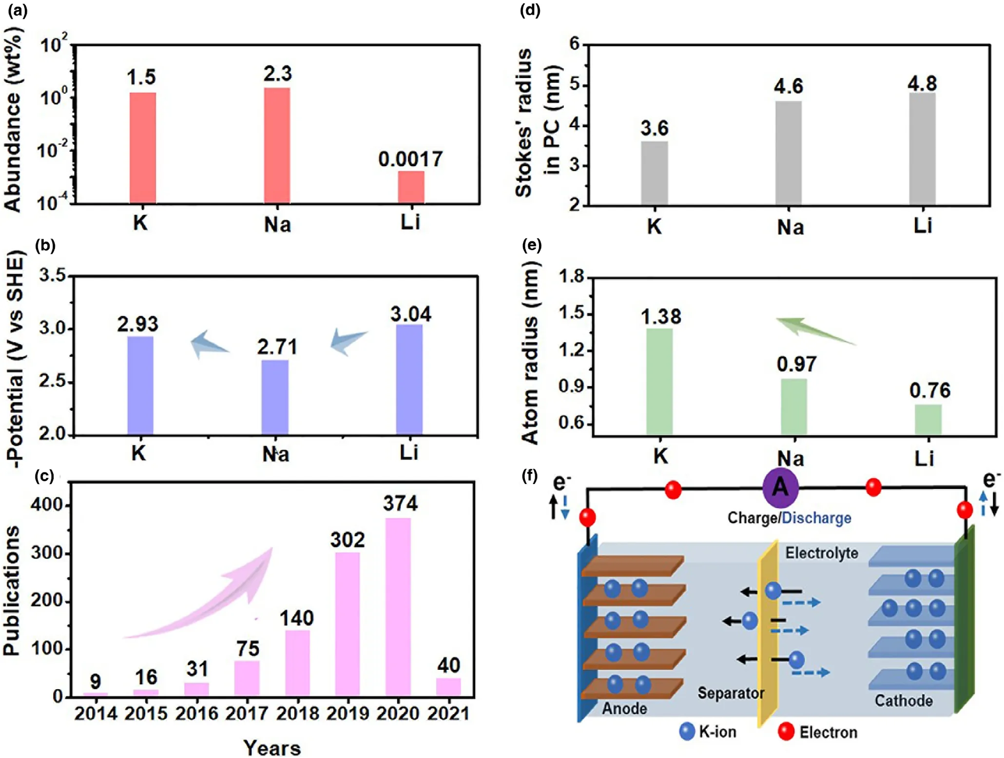
Figure 1. a) Abundance of K, Na, and Li resources in crust; b) standard reduction potential of K/K+, Na/Na+, and Li/Li+; c) Numbers of publication about KIBs from Web of Science (accessed on 5 January 2021); d) Stokes radius of K+, Na+, and Li+ in propylene carbonate (PC); e) atom radius of Li, Na, and K and f) schematic illustration of a “rocking-chair” KIBs.
With the advent of the large-scale energy,new types of energy storage devices have been developed rapidly,which draws attention to previous works.[37,38]It is a wonder that graphite which cannot be effective inserted by Na-ion but can accommodate the considerable K-ion. Since the works about graphite for KIBs have been reported and delivered a considerable electrochemical performance,the further investigation of graphite aroused great attention. Typically,Jian et al.[33]first found that the electrochemical K-ion insertion into graphite with nonaqueous electrolyte of 0.8 M KPF6in ethylene carbonate(EC)and diethyl carbonate(DEC)(1:1)mixed solution,which presented a high reversible capacity of 273 mAh g−1at a current density of 7 mA g−1. This result demonstrated that the pure graphite who failed in NIBs could be effectively used in KIBs.To investigate the electrochemical reaction process in graphite,the ex situ XRD in the selected potassiation-depotassiation states in the initial cycle was provided,as shown in Figure 2a,b.It was found that the diffraction peaks of graphite disappeared when discharging to 0.3–0.2 V and two new peaks at 22.0° and 29.4° arose,indicating that the formation of KC36(stage 3). In KC36, it should be constituted by third pair of host graphene layers and one layer of K atom.With the further potassiation,the K-ion would continue to insert into the graphene layers, resulting in the appearance of new peaks at 20.2°and 30.6°,which indicated that KC36was transformed into KC24.Finally, a pure phase of KC8was detected with the further discharging to 0.01 V. With the full potassiation-depotassiation cycle, the phase of KC8was back to graphite. A lower peak intensity of graphite appeared after potassiation-depotassiation cycle, indicating that the existence of structural damage after the K-ion insertion. In order to guide the graphite in the potassium storage process,Huo et al.provided a calculation at different stages for K-ion storage of graphite,as shown in Figure 2c,d.[32]According to the results, KC6could not be generated during the electrochemical reaction. When analyzing the results of the calculations for the staging sequence KC24(Stage II) →KC8(Stage I), they found that KC24(Stage II, theory b) showed 0.1 eV less stable than that of KC24(Stage III, theory a), and the potential profile also presented an increase in voltage from Stage II to Stage I. But it was unobserved this result related voltage increase in experiment process. Contrarily, a staging in which the Coulomb repulsion between ions separated by empty galleries was minimized, and the corresponding to the staging mechanism:KC24−Stage-III→KC16−Stage-II and KC8−Stage-I was energetically more stable. According to the above results, theory a should be better consistent with the potential profile obtained in the experiments (black solid line and averaged red dotted line) These results seem to indicate that the staging of K ions intercalation into graphite in electrochemical experiments behaved similarly to the one in Li intercalation.
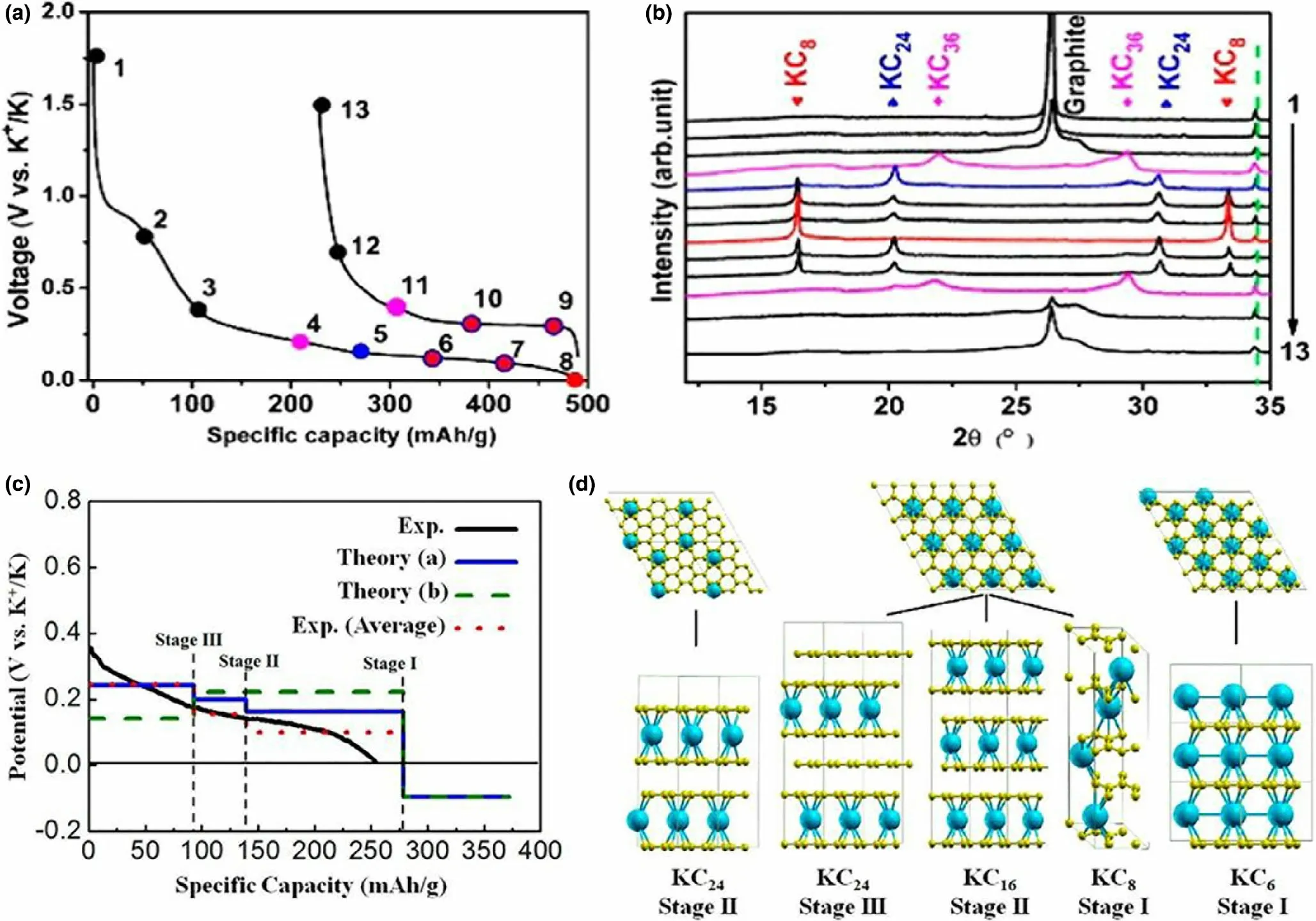
Figure 2. a) First-cycle charge-discharge potential profiles at C/10, b) XRD patterns of electrodes corresponding to the marked SOCs in (a). Reproduced with permission.[33] Copyright 2015, American Chemical Society. c) Calculated potential plateau for K-ion intercalation into graphite for different stages. Blue line(Theory a) corresponded to an intercalation staging: KC24(Stage III) →KC16 (Stage II) →KC8 (Stage I). Green dotted line (Theory b) represented calculated values for the previously reported staging: KC24 (Stage II) →KC8 (Stage I). Red dotted line was behalf of the averaged experimental data shifted by 26 mAh g−1 to correct the capacity contribution from SEI layer formation. d) Scheme of the different stages of K-intercalated graphite. Reproduced with permission.[32] Copyright 2015, American Chemical Society.
The electrode/electrolyte interface is also deemed as an important factor for KIBs. It is of great significance to investigate the formation of solid electrolyte interphase(SEI)layer in graphite for K-ion storage.Naylor et al.[39]investigated the composition and the formation process of SEI layer as well as K-ion insertion into graphite anodes in KIBs.To analyze the SEI layer,they made an analysis at three probing depths up to ~50 nm of graphite during different potassiation-depotassiation states by the energy-tuned synchrotron-based X-ray photoelectron spectroscopy (XPS). According to the result of energytuned synchrotron-based XPS,it was considered that the formation of SEI layer mainly occurred at the voltage region of 0.35–0.15 V in discharge stage (Figure 3). It was found that vast SEI layer formed in KPF6/DEC-EC electrolyte system at low potentials during the potassiation process. In the subsequent depotassiation process, the thick SEI layer was partially stripped from the electrode, indicating that the SEI layer was unstable. The energy-tuned synchrotron XPS results also presented that the layered structure SEI was mainly composed of organic layer and inorganic layer, containing carbonates, K-F/P-O-F compounds, and compounds associated with C–O/C=O. According to these results, they suggested that the SEI layer would undergo a characteristic “breathing” phenomenon on the charge of the electrode, whereby it was partially redissolved, stripped, or broken up.Consideration of large volume change,the potassiated graphite would suffer high mechanical strain, which had been demonstrated by Raman spectrum. In addition,the high mechanical strain of electrode would also cause some surface instability/exfoliation of graphite particles in the initial cycle,resulting in the SEI layer unsuitable for passivation of electrode surface.
3. How to Improve the Performance of Graphite for KIBs?
After the investigation of reaction mechanism of graphite for KIBs,some scientists turn to another path to improve the K-ion storage performance. In this section, we summarize and classify the previous works involving the methods improve the performance of graphite for KIBs. The detail methods mainly include the design of graphite structure,selection of appropriate binder,solvent chemistry,and salt chemistry and we will discuss these points as below.
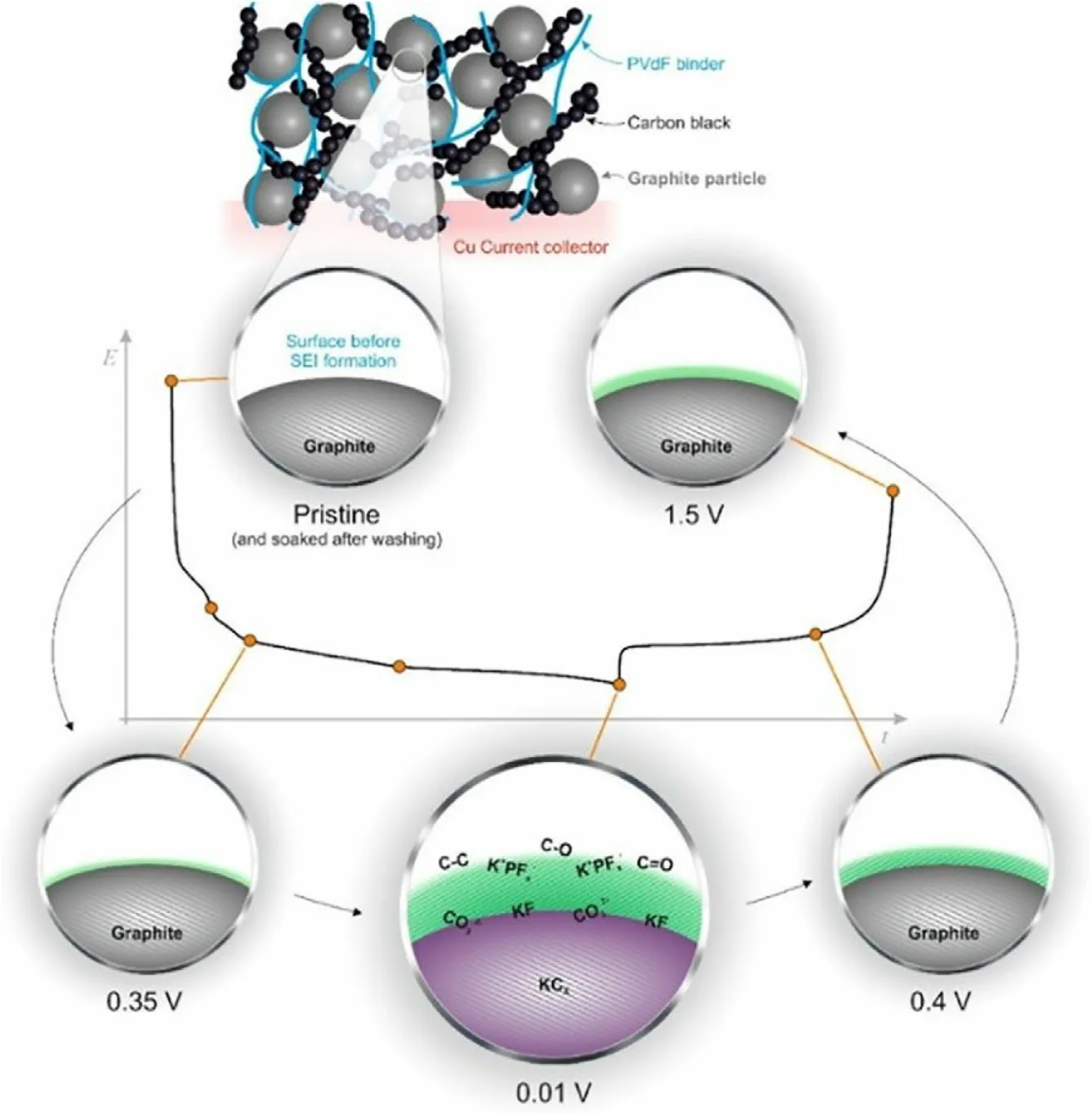
Figure 3. Schematic diagram for the process of SEI formation and K-ion insertion for graphite anodes in KIBs. Reproduced with permission.[39] Copyright 2017, American Chemical Society.
3.1. Design of Graphite Structure
Because the appropriate structure including the morphologies, crystalline states, surfaces, and defects of graphite, can facilitates the K-ion transmittability and adsorbability, developing new types of graphite structure becomes the first path to improve the K-ion storage performance. Carboni et al.[40]compared the K-ion storage performance of graphite electrode using different coating processes. They found that the graphite electrode derived from sizing by ball milling method presented better performance than that derived from sizing by conventional mixed method. Due to the slight mechanical exfoliation of graphite after ball milling, some simultaneous defects were formed,resulting in an improved K-ion storage performance. Rahman et al.[41]developed a liquid-phase ball milling method conducted under low-energy conditions for modification of graphite structure. Because the obtained graphite presented thin flakes with high surface area, it achieved a much improved electrochemical performance (a reversible capacity of 227 mAh g−1at 100 mA g−1after 500 cycles) compared with untreated graphite. Tai et al.[42]utilized KOH as etching agent at high temperature under inert atmosphere to obtained activated graphite.After activation,the modified graphite presented many nanosized carbon sheet with large number of pores resulting in a seven times improvement of K-ion diffusion coefficient, which could be beneficial to the rapid intercalation-deintercalation of K ions.Li et al.[43]designed mildly expanded graphite with adjustable interlayer distance via a wet chemical oxidation route to enhance its K-ion storage performance.According to the optimation of mass ratio between graphite and potassium permanganate oxidant,the mildly expanded graphite delivered a remarkable improvement capacity of 88 mAh g−1at 1.5 A g−1, which was ascribed to the improvement of K-ion transfer ability of graphite after the adjustable interlayer distance.Cao et al.[44]constructed graphitic carbon nanocage for KIBs, as shown in Figure 4a,b.Because of the concentric arrangement of carbon layer in the cage-like structure,this type of graphitic carbon could efficaciously reduce anisotropy, which helped to avoid interlayer slipping. Furthermore, the hollow cage-like structure also accommodated the strain relaxation during potassiation-depotassiation process,which contributed to the improvement of cyclic stability. Under the construction of graphitic carbon nanocage, it presented an excellent cyclability and superior depotassiation capacity of 175 mAh g−1even at a high current density of 35 C (about 10 A g−1). The K-ion storage behaviors of graphitic carbon nanocage are mainly constituted by redox reactions(intercalation/deintercalation) and double-layer capacitance (surface adsorption/desorption). Xing et al.[45]obtained polynanocrystalline graphite by chemical vapor deposition, which possessed a unique structure different from low-dimensional nanocrystalline carbon materials. This polynanocrystalline graphite essentially presented hollow with randomly arranged nanosized graphite building blocks, as shown in Figure 4c. This novel graphite structure with disorder in nanometric scales but order at atomic scales presented an excellent K-ion storage performance (about 100 mAh g−1at 100 mA g−1after 300 cycles). In addition, some design of graphite structure including the surface modification[46],doping,[34,47]and structural nanocrystallization[48]et al. was reported,which also remarkably improved the K-ion storage performance.
3.2. Selection of Appropriate Binder
From the aforementioned optimization of graphite structure, it is found that some complicated processes are not negligible. To simplify the process and improve the performance of graphite, several other optimizations were also considered. As a kind of essential constitution in KIBs, binders gradually obtained the attention of researchers.[49,50]Therefore, some works attempted to optimize the binder to further improve the K-ion storage performance of graphite. Komaba et al.[51]investigated the K-ion storage performance of graphite and found that the graphite in carbonate ester solution exhibited a reversible potassiation-depotassiation. After fully intercalation of K-ion, graphite cooperated with carboxymethylcellulose (CMC) binder delivered 244 mAh g−1at 25 mA g−1. To improve the K-ion storage performance,they also optimized different binders to analyze the effect of binder in graphite for KIBs. Through the use of polyvinylidene fluoride(PVDF), sodium polyacrylate (PANa), and CMC as binders, they found that graphite using CMC binder exhibited better Coulombic efficiency (CE) (Figure 4d–f), which was attributed to the preformed SEI layer by CMC binder in fresh state. Wu et al. also investigated the effects of functional binders on graphite in KIBs.[35]They also found that in the aqueous system binders including CMC and PANa could decrease the electrolyte decomposition on the surface of graphite particle, which contributed to the restriction of the capacity fading.
3.3. Solvent Chemistry
The electrolyte is also an essential constitution in KIBs.By optimizing the electrolyte, the rapid migration of K ions can be realized.[17,23,52]Furthermore, the formation of SEI layer is also closely related to the selection of electrolyte.[53,54]Constructing robust and thin SEI layer will promote the stability of electrode. In electrolyte, solvent chemistry can significantly enhance the K-ion storage performance of graphite, which causes much attention for the investigation. To understand the enhancement mechanism of K-ion storage, several attempts involving solvent chemistry have been reported. Zhao et al.[55]compared with the K-ion storage performance of graphite using 1 M KPF6in EC-PC, EC-DEC, and EC-dimethyl carbonate (DMC) as electrolytes. It was found that graphite using KPF6/EC-PC electrolyte delivered a capacity retention of 220 mAh g−1after 200 cycles at 20 mA g−1between 0–1.5 V and obtained an initial CE of 66.5%. Compared with the KPF6/EC-PC electrolyte, the batteries using KPF6/EC-DEC and KPF6/EC-DMC electrolytes exhibited lower CE, which was caused by the more severe decomposition of DEC and DMC that were unstable at low voltage. It was also found that the battery using KPF6/EC-DMC electrolyte presented the worst cycling performance with a continuous capacity decrease and failed after 140 cycles.This phenomenon should be associated with the poor electrochemical stability of DMC upon reduction. In addition, Kim et al.[56]attempted graphite cooperated with ether-based electrolyte for NIBs and were surprised to find that Na-ion could intercalate into graphite, which should be due to the occurrence of Na+-solvent co-intercalation behavior. This result subverted the envision about the NIBs. From this inspiration, some works involving graphite with ether-based electrolyte were carried out. Wang et al.[36]compared with the K-ion storage performance of graphite in carbonate-based and ether-based electrolytes. Both of them, the esterbased electrolyte was constituted by the 1 M KPF6in EC-DEC mixture (KPF6/EC-DEC) and the ether-based electrolyte was composed of 1 M KPF6in dimethoxyethane solution (KPF6-DME). It was found that the graphite in KPF6-DME electrolyte had a much better capacity retention behavior with a capacity of 80 mAh g−1versus 17 mAh g−1in KPF6/EC-DMC electrolyte after 700 cycles and also presented higher rate performance. According to the results from ex situ XRD, Raman, and transmission electron microscope (TEM)techniques, they proved that the K+intercalation into graphite with formation of KC8in EC-DMC-based electrolyte. Different from the K-ion storage reaction of graphite in ester-based electrolyte, the K+-ether group co-intercalated into the graphite in ether-based electrolyte, which presumably had a charge shielding effect with a consequence of low interaction force with graphite leading to a high insertion voltage, highly K+diffusion rate, and low volume expansion (<10%). To further illustrate the unique K+-solvent co-intercalation mechanism in ether-based electrolyte,Li et al.[57]used natural graphite as anode cooperated with 1 M potassium trifluoromethanesulfonate (KFS) in diethylene glycol dimethyl ether (DEGDME) for KIBs.To monitor the structural evolution of graphite in real time during potassiation-depotassiation process, they designed an encapsulated electrolytic cell as in situ XRD battery.From the result of in situ XRD,it was found that the c lattice parameter of electrode after discharge is about 12.09 ˚A,which should be the solvent co-intercalated into the layers of natural graphite. They also optimized the structures of [K-DEGDME]+complexes intercalated into graphite and the complex presented that the solvated K-ion was coordinated with three O atoms in DEGDME and the detailed size of the complex ion was 9.00 × 4.82 × 2.94 ˚A3. The corresponding structures of 1, 2, and 3 [K-DEGDME]+complexes intercalated into graphite were shown in Figure 5a.In consideration of the interlayer distance of 12.09 ˚A from in situ XRD, the structure composed of two [K-DEGDME]+complexes should be more reasonable. The electrode/electrolyte interface is also deemed to an important factor for KIBs and the electrode/electrolyte interface of graphite cooperated with etherbased electrolyte also need to be investigated. Lei et al.[58]employed ester-based and ether-based solvents as the electrolytes for KIBs. They found that the decomposition of ester-based electrolyte resulted in a thickening of SEI layer (Figure 5b), which suggested the main responsibility for the capacity decay of graphite for KIBs. For comparison, graphite cooperated with ether-based electrolyte presented better cyclic stability, which should be ascribed to the relative stability of DEGDME on the interfaces. Furthermore, a slight graphitic structure degradation of graphite in ether-based electrolyte could be detected, which also facilitated the cyclic stability for KIBs.
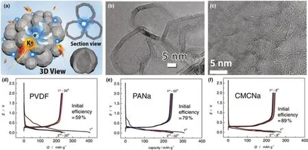
Figure 4. a) Schematic illustration of the structure and b) TEM image of graphitic carbon nanocage. Reproduced with permission.[44] Copyright 2018, WILEYVCH. c) TEM image of polynanocrystalline graphite. Reproduced with permission.[45] Copyright 2017, American Chemical Society. Charge-discharge curves of graphite with d) PVDF, e) PANa, and f) CMC binders. Reproduced with permission.[51] Copyright 2015, Elsevier.
Considering the safety of battery,some attempts have also been paid to the non-flammable designs by solvent chemistry. Zeng et al.[59]selected trimethyl phosphate (TMP) solvent as electrolyte in graphite electrode for KIBs and investigated the effect of concentration of salt.The result showed that the graphite in 3.3 M KFSI/TMP electrolyte presented a reversible specific capacity of 214 mAh g−1at 30 mA g−1after 80 cycles. According to the result, they also investigated the electrochemical enhancement mechanism and found that a stable saltderived passivation layer was created on graphite surface, which was attributed to the stable K-ion solvate in highly concentrated salt electrolyte. An exciting thing was that such highly concentrated salt electrolyte also presented a greatly improvement of the safety of battery.Figure 5c,d showed the direct flammability tests image of carbonate electrolyte and KFSI/TMP electrolyte and result displayed that KFSI/TMP electrolyte cannot be ignited while carbonate electrolyte was highly combustible.Liu et al.[60]introduced a new concept of adopting electrolyte additives to improve the non-flammable electrolyte for KIBs without the need of concentrated electrolyte strategies.In consideration of instability of non-flammable TMP, they made 1 M KFSI into TMP with additive of ethylene sulfate(DTD)as electrolyte.In the case of fire,this type of electrolyte appeared non-flammable. They suggested that the positive effect of DTD additive contributed to the formation of stable SEI layer,which presented more robust to restrain the K+-solvent co-insertion (Figure 5e–h). However, an interesting phenomenon was that the fresh graphite cycled in the DTD-containing electrolyte could not maintain the stability when the graphite@SEI exchanged the DTDfree electrolyte in a new battery. These results indicated that the compatibility of electrolyte rather than SEI layer was the dominant factor in graphite for K-ion storage.
3.4. Salt Chemistry
Salt chemistry is also introduced in the graphite for KIBs, which includes two aspects of salt anion optimization and salt concentration optimization.Niu et al.[61]analyzed the effects of salt concentrations in electrolyte for KIBs with the salt of potassium bis(fluorosulfonyl)amid(KFSI) and the solvent of DME. The result showed that the graphite cooperated with high salt concentration electrolyte (7 mol kg−1) presented a high K-ion storage capacity of 232 mAh g−1with low insertion voltage and high CE.Shimizu et al.[62]investigated three kind of K salts of KFSI,KTFSI,and KPF6in EC-DEC solution as electrolytes in graphite for KIBs.The result showed that graphite in KFSI-containing electrolyte presented an excellent reversible specific capacity of 202 mAh g−1at 28 mA g−1after 100 cycles, which was higher than that of graphite in KTFSI-containing (96 mAh g−1at 28 mA g−1after 100 cycles) and KPF6-containing (114 mAh g−1at 28 mA g−1after 100 cycles) electrolytes. From the ex situ Raman spectra of graphite electrode after 100 cycles, it was found that the ID/IGratio of graphite in KFSI-containing electrolyte was 0.52, which was lower than that of graphite in KPF6-containing (0.85) electrolytes. These results indicated that the crystallinity of graphite electrode material was maintained in KFSI-containing electrolyte.Furthermore,the ID/IGof the graphite after the first cycle presented that KPF6-containing (0.54) electrolytes had the larger values than KFSI-containing electrolyte (0.40). The higher ratio indicated that the SEI layer formed in the first cycle would damage to the graphite structure greatly. PF6anion was more easily inserted into graphite and diffused than large-size TFSI, which led to volume expansion of electrode material and reduced Coulomb efficiency by constantly forming new surface layers. Fan et al.[63]demonstrated an effective method that adopted novel high-concentration salt of KFSI in ethyl methyl carbonate (EMC) solvent as electrolyte to improve the cycle stability of graphite for KIBs.According to the operando XRD and ex situ XPS,they demonstrated that the graphite electrode using such a concentrated KFSI-EMC electrolyte could form a robust inorganic-rich passivation layer on the surface,which would significantly improve the cycle time and stability. Consequently, the KIBs with graphite anode could operate for over 2000 cycles (running time over 17 months, as shown in Figure 6a) with negligible capacity decay and had a high area capacity over 7.36 mAh cm−2with a high mass loading of 28.56 mg cm−2(Figure 6b,c). The aforementioned work demonstrated that relatively high salt concentration in electrolyte contributed to the improvement of graphite for K-ion storage. Despite these progresses,high salt concentration electrolyte also faces some issues including the low ionic conductivity and the increase cost,which impede the practical applications of these type of electrolytes. To overcome these disadvantages, localized high-concentration electrolytes adaptive with graphite were proposed. Qin et al.[64]utilized fluorinated ether to dilute the high-concentration KFSI/DME electrolyte forming localized high-concentration electrolyte, which is adapted to graphite for KIBs.This localized high-concentration electrolyte presented a superb oxidation stability,low flammability,and enhanced ionic conductivity.More critically,graphite(with a high mass loading of ≈8 mg cm−2)cooperated with this localized high-concentration electrolyte presented a reversible capacity of 200 mAh g−1at 25 mA g−1over 300 cycles and a high initial CE of 82.3%.
Based on the above discussion,we have summarized several kinds of methods to improve the performance of graphite for KIBs, including the design of graphite structure,selection of appropriate binder,solvent chemistry, and salt chemistry. Furthermore, we also list the important parameters including cycling stability, rate capability, binder, and electrolyte of recent work involved graphite-based anode for KIBs, as shown in Table 1. At the same time,we are looking forward to more methods to further improve the performance of graphite in KIBs.
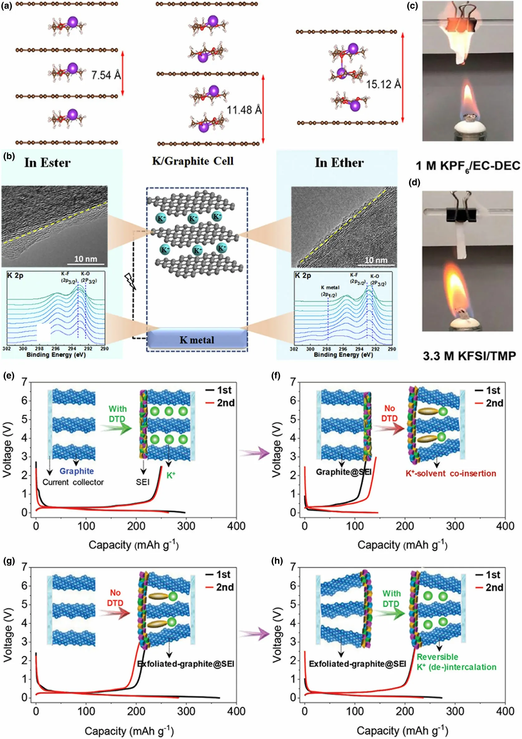
Figure 5. a) Optimized structures of 1, 2, 3 [K-DEGDME]+ complexes intercalated in graphite. Purple, white, gray, and red balls represent K, H, C, and O atoms, respectively. Reproduced with permission.[57] Copyright 2018, WILEY-VCH. b) TEM images and in depth XPS analysis of graphite in ester-based and ether-based electrolytes. Reproduced with permission.[58] Copyright 2016, Elsevier. Flammability tests in c) 1 M KPF6/EC-DEC and d) 3.3 M KFSI-TMP electrolyte. Reproduced with permission.[59] Copyright 2019, The Authors. e) K+ (de-)intercalation within fresh graphite in the electrolyte with DTD additive;meanwhile, the graphite@SEI was formed. f) K+ (de-)intercalation within graphite@SEI after exchanging the electrolyte without DTD additives. g) K+ (de-)intercalation within the fresh graphite in the electrolyte without DTD additives, where the exfoliated-graphite@SEI can be also formed. h) K+ (de-)intercalation within exfoliated-graphite@SEI after exchanging the electrolyte with DTD additives. Reproduced with permission.[60] Copyright 2020, WILEY-VCH.
4. “Relative Energy Density” to Scientifically Evaluate the Performance of Graphite for KIBs
In the previous works, most researchers mainly used the parameter of specific capacity to confirm the K-ion storage performance of anode materials.All the results showed that some sulfides,phosphides et al.as anode materials presented high specific capacity for K-ion storage.[67–69]As anode materials, the voltage plateau always plays an important part of performance and the low voltage plateau of anode is more valuable in anode materials because the open-circuit voltage of Kion full battery is determined by the potential difference between the anode and cathode. To better evaluate the electrochemical performance of anode materials accurately and conveniently, a concept of “relative energy density” was proposed, which not only included the specific capacity, but also contained the charge-discharge potential plateau in anode materials, which helped to effectively evaluate the electrochemical performance in consideration of working potential.[70]The corresponding equations are as follows:
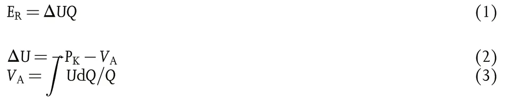
In aforementioned equations,the ER,Q,VA,and PKrepresented relative energy density, specific capacity, average potential, and relative standard hydrogen potential of K(−2.93 V vs K/K+),respectively.The VAshould be the average discharging potential in discharge process,and the VAis also the average charging potential in charging process.ΔU is the different value between −PKand VA.The corresponding typical legend is shown in Figure 7a,b. In this work, the acidized carbon cloth was used as anode and the corresponding relative energy density could be calculated,as shown in Figure 7c.It is found that acidized carbon cloth presented a high ER,which resulted from the low charge-discharge voltage plateau for K-ion storage.An additional parameter of the ratio of discharging relative energy density and charging relative energy density. It was defined as relative energy conversion efficiency. High relative energy conversion efficiency of anode indicated the less energyloss during the energy conversion process. The corresponding relative energy conversion efficiency of acidized carbon cloth is also obtained in Figure 7d. In graphite-based anode materials, we found that all of them presented a very low charge-discharge voltage plateau for K-ion storage. Although graphite always presents a relatively lower specific capacity (similar to the result of acidized carbon cloth) compared with other anode materials including sulfide and phosphide, it is a promising anode in all probability for KIBs,which is due to the higher relative energy density of graphite.
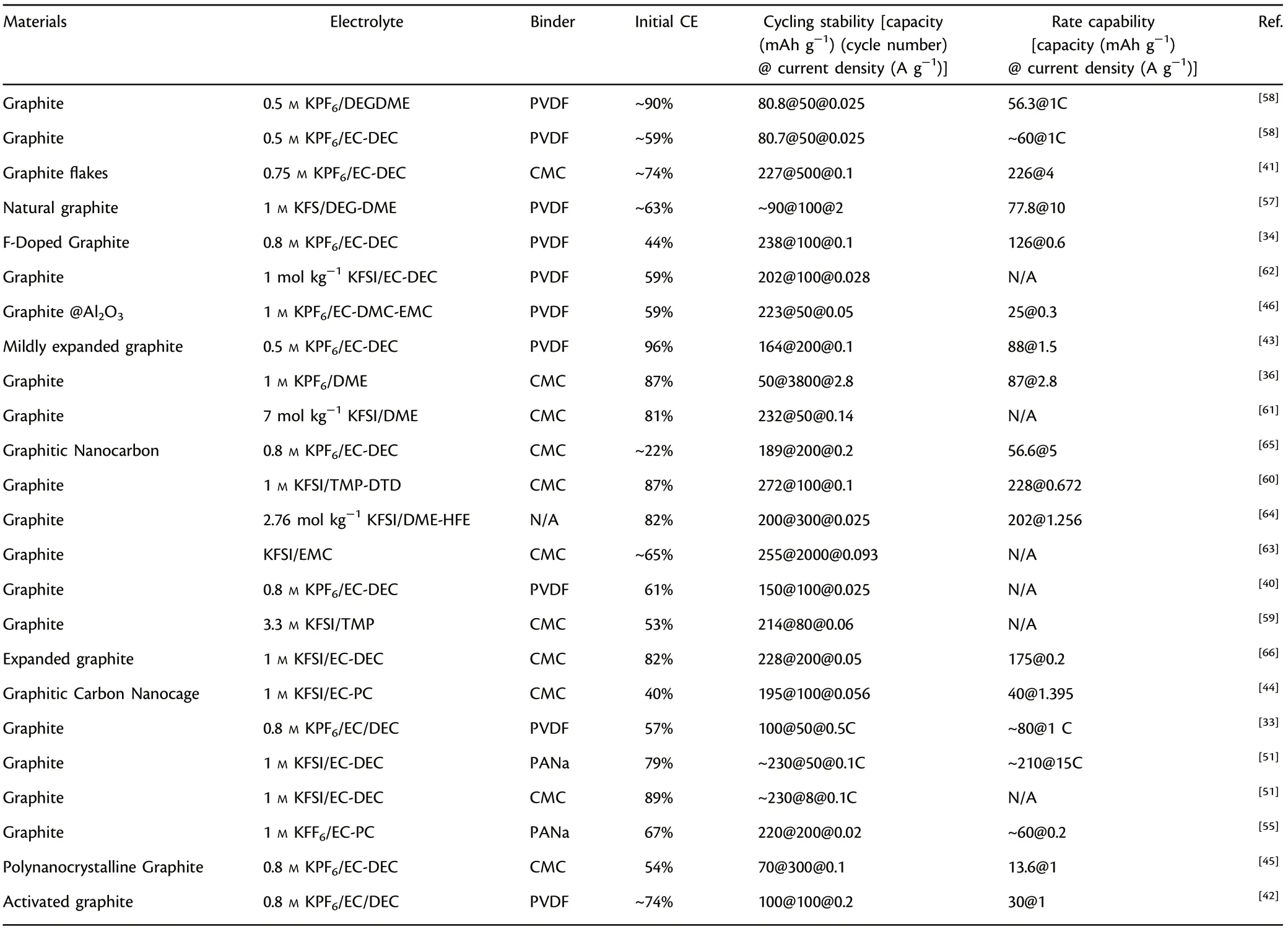
Table 1. Electrochemical performances of graphite anode materials for KIBs.
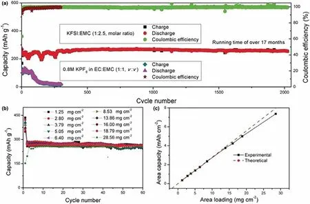
Figure 6. a) Cycle performance of graphite with two different electrolytes at approximately C/3 (1 C = 279 mA g−1); b) cycle performance with different area mass loading of graphite using KFSI-based electrolyte at C/14; c) area capacity of graphite calculated from the theoretical and experimental results.Reproduced with permission.[63] Copyright 2020, WILEY-VCH.
5. Conclusions and Perspectives
The development of high specific capacity with low voltage anode materials becomes an important concern of current KIBs.Different from performance of graphite in NIBs, graphite presents excellent electrochemical performance for K-ion storage.Therefore,exploring high-performance graphite-based anode materials becomes a current research focus. In this review, we mainly discuss the electrochemical reaction mechanism of graphite during potassiation-depotassiation process and analyze the effects of electrode/electrolyte interface on graphite for K-ion storage.In addition,we also summarize several kind methods to improve the performance of graphite for KIBs. The details are as follows: 1) the design of graphite structure to facilitate the insertiondeinsertion of K-ion and remission of the strain relaxation during potassiation-depotassiation process; 2) the selection of appropriate binder to enhance the adhesion behavior of graphite to improve its K-ion storage performance; 3) optimization of electrolyte by solvent chemistry to promote the K-ion migration capacity; 4) exploitation of salt chemistry to optimize the anion and concentration, thus realizing the formation of high stability interface layer on graphite. Meanwhile, we also emphasize a concept of “relative energy density”according to our previous work and we suggest that this concept can use to accurately evaluate the genuine electrochemical performance of graphite anode involved the specific capacity and potential.
Although some satisfactory results have been obtained in the current work involving graphite anode for KIBs, considerable challenges still remain and are listed in below: 1) Most of graphite only presented excellent K-ion storage performance at low current density and always received poor performance in high current density. Therefore, further developing high-rate performance of graphite-based anode is critical in practical KIBs. 2) High mass loading graphite anode is an important way for high-performance KIBs in the future. However, current graphite electrodes are principally in low mass loading,which is far from meeting the demands of commercialized KIBs. 3) High initial CE is helpful for the improvement of cathode utilization. However, current graphite only presented a relatively low initial CEs for KIBs,which will result in the significant decrease of cathode utilization.
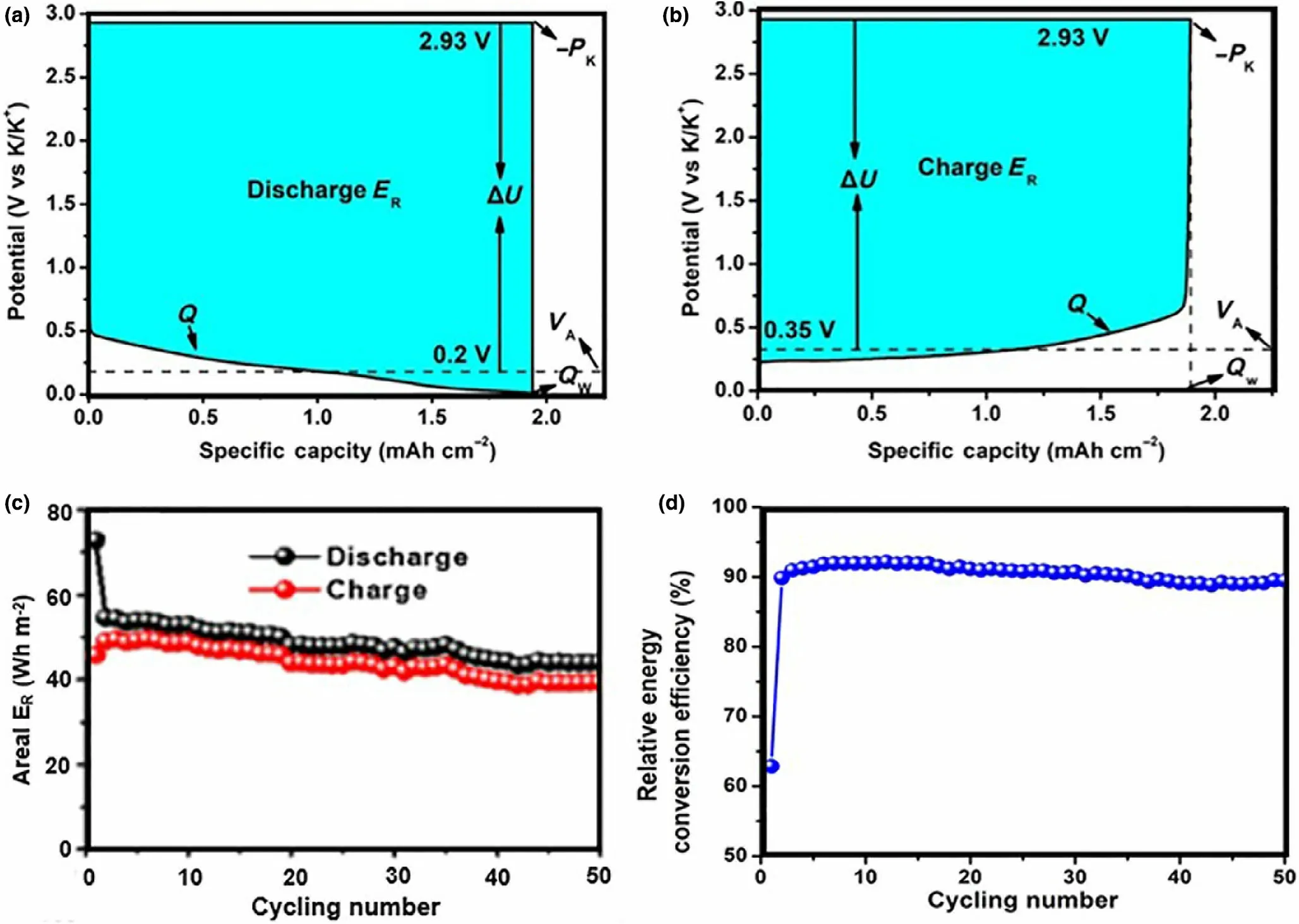
Figure 7. Typical legends for the determination of the relative energy density (ER) of a) discharge ER and b) charge ER; c) areal ER and d) relative energy conversion efficiency of acidized carbon clothes electrode at the charge and discharge process. Reproduced with permission.[70] Copyright 2020, Chinese Chemical Society.
Acknowledgements
We thank the financial supports from the National Natural Science Foundation of China(51772135,52002115),the Fundamental Research Funds for the Central Universities (21617330), and Science and Technology Development Project of Henan Province(212102210487).
Conflict of Interest
The authors declare no conflict of interest.
Keywords
electrochemical reaction mechanism, graphite anode, K-ion batteries,methods to improve performance
Received: March 2, 2021
Revised: March 15, 2021
Published online: March 23, 2021
[1] Y. Lyu, X. Wu, K. Wang, Z. Feng, T. Cheng, Y. Liu, M. Wang, R. Chen, L.Xu, J. Zhou, Adv. Energy Mater. 2021, 11, 2000982.
[2] N. F. Zhou, W. Qin, C. Wu, C. K. Jia, J. Alloys Compd. 2020, 834,155073.
[3] L. Li, R. Zhao, D. Pan, S. Yi, L. Gao, G. He, H. Zhao, C. Yu, Y. Bai, J.Power Sources. 2020, 450, 227677.
[4] T. Or, S. W. Gourley, K. Kaliyappan, A. Yu, Z. Chen, Carbon Energy.2020, 2, 6.
[5] C. Yang, S. Xin, L. Mai, Y. You, Adv. Energy Mater. 2020, 11, 2000974.
[6] R. Rajagopalan, Y. Tang, X. Ji, C. Jia, H. Wang, Adv. Funct. Mater. 2020,30, 1909486.
[7] M. Sha, L. Liu, H. Zhao, Y. Lei, Energy Environm. Mater. 2020, 3, 56.
[8] J.Zheng,Y.Wu,Y.Sun,J.Rong,H.Li,L.Niu,Nano-Micro Lett.2020,13,12.
[9] T. Liu, Y. Zhang, Z. Jiang, X. Zeng, J. Ji, Z. Li, X. Gao, M. Sun, Z. Lin, M.Ling, Energy Environm. Sci. 2019, 12, 1512.
[10] H. S. Hirsh, Y. Li, D. H. Tan, M. Zhang, E. Zhao, Y. S. Meng, Adv. Energy Mater. 2020, 10, 2001274.
[11] F. Li, Z. Wei, A. Manthiram, Y. Feng, J. Ma, L. Mai, J. Mater. Chem. A.2019, 7, 9406.
[12] S. Dai, L. Wang, M. Cao, Z. Zhong, Y. Shen, M. Wang, Mater. Today.Energy 2019, 12, 114.
[13] X. Zhang, D. Yang, X. Rui, Y. Yu, S. Huang, Curr. Opin. Electrochem.2019, 18, 24.
[14] K. Zhang, Q. He, F. Xiong, J. Zhou, Y. Zhao, L. Mai, L. Zhang, Nano Energy. 2020, 77, 105018.
[15] S. Ghosh, M. A. Makeev, M. L. Macaggi, Z. Qi, H. Wang, N. N. Rajput, S.K. Martha, V. G. Pol, Mater. Today. Energy 2020, 17, 100454.
[16] J. Xie, J. Li, W. Zhuo, W. Mai, Mater. Today Adv. 2020, 6, 100035.
[17] J. Li, N. Zhuang, J. Xie, X. Li, W. Zhuo, H. Wang, J. B. Na, X. Li, Y.Yamauchi, W. Mai, Adv. Energy Mater. 2020, 10, 1903455.
[18] W. Zhang, Y. Liu, Z. Guo, Sci. Adv. 2019, 5, eaav7412.
[19] X. Wu, Y. Chen, Z. Xing, C. W. K. Lam, S.-S. Pang, W. Zhang, Z. Ju, Adv.Energy Mater. 2019, 9, 1900343.
[20] T. Hosaka, K. Kubota, A. S. Hameed, S. Komaba, Chem. Rev. 2020, 120,6358.
[21] K. Lei, C. Wang, L. Liu, Y. Luo, C. Mu, F. Li, J. Chen, Angew. Chem. Int.Ed. 2018, 57, 4687.
[22] X. Zhao, W. Wang, Z. Hou, G. Wei, Y. Yu, J. Zhang, Z. Quan, Chem.Eng. J. 2019, 370, 677.
[23] J. Xie, Y. Zhu, N. Zhuang, X. Li, X. Yuan, J. Li, G. Hong, W. Mai, J. Mater.Chem. A. 2019, 7, 19332.
[24] J. Wen, L. Xu, J. Wang, Y. Xiong, J. Ma, C. Jiang, L. Cao, J. Li, M. Zeng, J.Power Sources. 2020, 474, 228491.
[25] J. Cheng, L. Gao, T. Li, S. Mei, C. Wang, B. Wen, W. Huang, C. Li, G.Zheng, H. Wang, Nano-Micro Lett. 2020, 12, 1.
[26] B. Wang, H. Yang, Y. Feng, S. Zeng, L. Tan, R. Xu, L. Wang, R. Hu, Y. Yu,Mater. Today. Energy 2021, 20, 100627.
[27] L. Wang, S. Li, J. Li, S. Yan, X. Zhang, D. Wei, Z. Xing, Q. Zhuang, Z. Ju,Mater. Today. Energy 2019, 13, 195–204.
[28] A.Maurel,M.Courty,B.Fleutot,H.Tortajada,K.Prashantha,M.Armand,S.Grugeon,S.P.Panier,L.Dupont,Chem.Mater.2018,30,7484.
[29] D. S. Kim, Y. E. Kim, H. Kim, J. Power Sources. 2019, 422, 18.
[30] X. Li, Z. Liu, J. Li, H. Lei, W. Zhuo, W. Qin, X. Cai, K. N. Hui, L. Pan, W.Mai, J. Energy Chem. 2021, 53, 56.
[31] J. Li, D. Yan, T. Lu, W. Qin, Y. Yao, L. Pan, ACS Appl. Mater. Interfaces 2017, 9, 2309.
[32] W. Luo, J. Wan, B. Ozdemir, W. Bao, Y. Chen, J. Dai, H. Lin, Y. Xu, F.Gu, V. Barone, L. Hu, Nano Lett. 2015, 15, 7671.
[33] Z. Jian, W. Luo, X. Ji, J. Am. Chem. Soc. 2015, 137, 11566.
[34] Y. Zhao, L. Yang, C. Ma, G. Han, Energy Fuels. 2020, 34, 8993.
[35] X. Wu, Z. Xing, Y. Hu, Y. Zhang, Y. Sun, Z. Ju, J. Liu, Q. Zhuang, Ionics 2019, 25, 2563.
[36] L. Wang, J. Yang, J. Li, T. Chen, S. Chen, Z. Wu, J. Qiu, B. Wang, P. Gao,X. Niu, J. Power Sources. 2019, 409, 24.
[37] Y. Mizutani, T. Abe, K. Ikeda, E. Ihara, M. Asano, T. Harada, M. Inaba,Z. Ogumi, Carbon 1997, 35, 61.
[38] Z. H. Zhu, G. Q. Lu, Langmuir 2004, 20, 10751.
[39] A. J. Naylor, M. Carboni, M. Valyo, R. Younesi, A. C. S. Appl, Mater.Interfaces. 2019, 11, 45636.
[40] M. Carboni, A. J. Naylor, M. Valvo, R. Younesi, RSC Adv. 2019, 9, 21070.
[41] M. M. Rahman, C. Hou, S. Mateti, K. Tanwar, I. Sultana, A. M. Glushenkov, Y. Chen, J. Power Sources. 2020, 476, 228733.
[42] Z. Tai, Q. Zhang, Y. Liu, H. Liu, S. Dou, Carbon 2017, 123, 54.
[43] X. Li, Y. Lei, L. Qin, D. Han, H. Wang, D. Zhai, B. Li, F. Kang, Carbon 2021, 172, 200.
[44] B. Cao, Q. Zhang, H. Liu, B. Xu, S. L. Zhang, T. F. Zhou, J. F. Mao, W. K.Pang, Z. P. Guo, A. Li, J. S. Zhou, X. H. Chen, H. H. Song, Adv. Energy Mater. 2018, 8, 1801149.
[45] Z. Xing, Y. Qi, Z. Jian, X. Ji, ACS Appl. Mater. Interfaces. 2017, 9,4343.
[46] J. F. Chen, X. D. He, D. J. Li, J. M. Feng, Int. J. Energy Res. 2020, 44, 4260.
[47] H. Wang, G. Yang, Z. Chen, J. Liu, X. Fan, P. Liang, Y. Huang, J. Lin, Z.Shen, J. Power Sources. 2019, 419, 82.
[48] Z. Tai, Y. Liu, Q. Zhang, T. Zhou, Z. Guo, H. K. Liu, S. X. Dou, Green Energy Environm. 2017, 2, 278.
[49] J. L. Li, N. Zhuang, J. P. Xie, Y. Q. Zhu, H. J. Lai, W. Qin, M. S. Javed, W.G. Xie, W. J. Mai, ACS Appl. Mater. Interfaces. 2019, 11, 15581.
[50] J. Wu, Q. Zhang, S. Liu, J. Long, Z. Wu, W. Zhang, W. K. Pang, V. Sencadas, R. Song, W. Song, Nano Energy. 2020, 77, 105118.
[51] S. Komaba, T. Hasegawa, M. Dahbi, K. Kubota, Electrochem. Commun.2015, 60, 172.
[52] L. Madec, V. Gabaudan, G. Gachot, L. Stievano, L. Monconduit, H. Martinez, ACS Appl. Mater. Interfaces. 2018, 10, 34116.
[53] H. Wang, D. Zhai, F. Kang, Energy Environm. Sci. 2020, 13, 4583.
[54] J. Xie, X. Li, H. Lai, Z. Zhao, J. Li, W. Zhang, W. Xie, Y. Liu, W. Mai, A.Robust, Angew. Chem. Int. Ed. 2019, 58, 14740.
[55] J.Zhao,X.Zou,Y.Zhu,Y.Xu,C.Wang,Adv.Funct.Mater.2016,26,8103.
[56] H. Kim, J. Hong, Y.-U. Park, J. Kim, I. Hwang, K. Kang, Adv. Funct. Mater.2015, 25, 534.
[57] L. Li, L. Liu, Z. Hu, Y. Lu, Q. Liu, S. Jin, Q. Zhang, S. Zhao, S.-L. Chou,Angew. Chem. Int. Ed. 2020, 59, 12917.
[58] Y. Lei, D. Han, J. Dong, L. Qin, X. Li, D. Zhai, B. Li, Y. Wu, F. Kang,Energy Storage Mater. 2020, 24, 319.
[59] G. F. Zeng, S. L. Xiong, Y. T. Qian, L. J. Ci, J. K. Feng, J. Electrochem. Soc.2019, 166, A1217.
[60] G. Liu, Z. Cao, L. Zhou, J. Zhang, Q. J. Sun, J. Y. Hwang, L. Cavallo, L. M.Wang, Y. K. Sun, J. Ming, Adv. Funct. Mater. 2020, 30, 2001934.
[61] X. Niu, L. Li, J. Qiu, J. Yang, J. Huang, Z. Wu, J. Zou, C. Jiang, J. Gao, L.Wang, Solid State Ionics 2019, 341, 115050.
[62] M. Shimizu, T. Koya, A. Nakahigashi, N. Urakami, T. Yamakami, S. Arai,J. Phys. Chem. C. 2020, 124, 13008.
[63] L. Fan, R. Ma, Q. Zhang, X. Jia, B. Lu, Angew. Chem. Int. Ed. 2019, 58,10500.
[64] L. Qin, N. Xiao, J. Zheng, Y. Lei, D. Zhai, Y. Wu, Adv. Energy Mater.2019, 9, 1902618.
[65] W. Zhang, J. Ming, W. Zhao, X. Dong, M. N. Hedhili, P. M. Costa, H. N.Alshareef, Adv. Funct. Mater. 2019, 29, 1903641.
[66] Y. An, H. Fei, G. Zeng, L. Ci, B. Xi, S. Xiong, J. Feng, J. Power Sources.2018, 378, 66.
[67] Q. Peng, S. Zhang, H. Yang, B. Sheng, R. Xu, Q. Wang, Y. Yu, ACS Nano 2020, 14, 6024.
[68] Q. Liu, Z. Hu, Y. Liang, L. Li, C. Zou, H. Jin, S. Wang, H. Lu, Q. Gu, S.-L.Chou, Y. Liu, S.-X. Dou, Angew. Chem. Int. Ed. 2020, 59, 5159.
[69] J. P. Xie, Y. Q. Zhu, N. Zhuang, H. Lei, W. L. Zhu, Y. Fu, M. S. Javed, J. L.Li, W. J. Mai, Nanoscale. 2018, 10, 17092.
[70] J. Xie, J. Li, X. Li, H. Lei, W. Zhuo, X. Li, G. Hong, N. Hui Kwun, L. Pan,W. Mai, CCS Chem. 2020, 2, 791.
 Energy & Environmental Materials2022年2期
- Energy & Environmental Materials的其它文章
- Progress of Pb-Sn Mixed Perovskites for Photovoltaics:A Review
- Development Strategies in Transition Metal Borides for Electrochemical Water Splitting
- Polymer-/Ceramic-based Dielectric Composites for Energy Storage and Conversion
- Controllable Construction of Bifunctional CoxP@N,P-Doped Carbon Electrocatalysts for Rechargeable Zinc–Air Batteries
- Unveiling the Underlying Mechanism of Transition Metal Atoms Anchored Square Tetracyanoquinodimethane Monolayers as Electrocatalysts for N2 Fixation
- Rational Design of High-Performance Bilayer Solar Evaporator by Using Waste Polyester-Derived Porous Carbon-Coated Wood