
锂-空气电池的实用化之路:规避二氧化碳负面效应
2022-09-27 08:36王天杰王耀伟陈宇辉刘建鹏史会兵郭丽敏赵志伟刘春太彭章泉
物理化学学报 2022年8期
王天杰,王耀伟,陈宇辉,刘建鹏,史会兵,郭丽敏,赵志伟,刘春太,彭章泉 ,6,*
1南京工业大学能源科学与工程学院,材料化学工程国家重点实验室,江苏 南京 211816
2山东京博石化有限公司,山东 博兴 256500
3大连交通大学环境与化工学院,辽宁 大连 116028
4中国科学院大连化学物理研究所,谱学电化学与锂离子电池实验室,辽宁 大连 116023
5郑州大学材料科学与工程学院,材料成型及模具技术教育部重点实验室,河南 郑州 450002
6五邑大学应用物理与材料学院,广东 江门 529020
1 Introduction
Human society’s energy consumption continues to soar high with the rise of living standards globally. Access to renewable and reliable energy sources has become a focus of worldwide efforts1. In this context, electrochemical energy conversion and storage technologies including supercapacitors, fuel cells and batteries play an indispensable role2–5. Since Sony released its first generation Li-ion battery in 1990, the Li-ion batteries have become the must-have power supply for portable electronic devices6,7. However, in the long term current Li-ion technologies could hardly meet the demand of the rapidly evolving personal electronics and the emerging electric vehicles with long driving range. Toward building better batteries with higher energy density and lower cost, a few highly exergonic battery chemistries have been explored in the past few decades,among which the lithium-air battery (LAB) with an unrivalled theoretical specific energy (~3500 Wh·kg−1) has attracted much attention8–11. So far, LABs are still in their infant stage and there are many scientific and technological challenges need to be addressed before a practical device could be realized. These challenges include, but not limited to, stable electrolytes with high solubility and diffusivity of O212–14, highly efficient catalysts for Li2O2formation/decomposition15–17, strategies for inhibiting the formation of lithium dendrites18–20,etc. In the past decade, significant achievements have been made on these critical issues of LABs operated under the pure O2atmosphere8,21, and therefore these LABs shall be more precisely termed as lithium-oxygen batteries (LOBs). The LOBs are eventually a close system often carrying weighty O2 cylinder as the O2 feed, which sacrifices both the specific energy and the energy density. To maximize the energy capability of Li-O2electrochemistry, the ultimate LABs must discard the O2cylinder and access O2from the breathing air.
To shift from LOBs to LABs, the first step is to clarify the effects of other components (e.g.N2, CO2, and H2O) of the breathing air on the Li-O2electrochemistry. This is the main difference between the close LOB and the open LAB.Previously, there might be an over-optimistic assumption that these components would have negligible effects on the operation of LABs, which, however, is not true at any rate. Although the N2accounts for 78% of the air, it cannot be activated by the cathode with a working potential range of 2.0–4.5 Vvs.Li/Li+.Moreover, owing to the large amount of N2in the open system,the partial pressure of O2will be low and poor rate performance could be resulted for LABs. While in the close LOB, the feed gas is solely O2without the influence of other impurity gases, the electrochemical performance of the LOBs is expected to be superior to the LAB systems. However, the weighty O2cylinder of the close LOB system would limit both gravimetric and volumetric energy densities of the device. Very recently, Zhou’s group22reported a novel close LOB based on the conversion reaction of Li2O2/Li2O, which delivers a specific energy of 500 Wh·kg−1. With the assistance of Ni-based catalyst, they successfully realized the reversible conversion between Li2O and Li2O2without being further oxidized to O2. Although this cell configuration still faces the interfacial challenge due to the poor physical contact between Li2O2, Li2O, and Ni catalyst, it opens a new path to pursue an alternative beyond Li-ion batteries. The effect of H2O in LABs is complicated and has been reported to have the positive effects for cathode reaction such as improved discharge capacity and reduced overpotential, but it might change the desired discharge product Li2O2to LiOH and bring more side reactions upon recharge23–25. Moreover, the lithium anode can be corroded in the presence of residue H2O in the electrolyte26,27. Water-proof membranes and Li anode protection strategies proved to be capable of eliminating the negative effects of H2O28,29.
The concentration of CO2in the air is as low as ~ 300 ppm and such a low concentration can bring severe consequences to LABs30. On one hand, CO2 has a high solubility in common organic solvents (typically 1–2 order of magnitude higher than O2) and can transform to Li2CO3and other organic carbonates31.Li2CO3, a wide bandgap insulating solid, can increase the charging voltage significantly when accumulated on the cathode surface, and aggravate the decomposition of cathode materials and electrolytes at high charging voltages32,33. Besides understanding the reaction mechanism of CO2 in LABs, a better way to LABs is to completely remove the CO2from the breathing air before it enters the LAB system34,35. However,removing CO2from the breathing air proved to be a significant challenge36. A filter with a specific pore size does not work well due to the small difference in the kinetic radius of the CO2 and O2 molecules. The diameter of CO2 is 0.33 nm and 0.346 nm for O2, the size of CO2is slightly smaller than that of O2so that the mixture of O2and CO2cannot easily be separated physically by molecular filtration. It is notable that the CO2separation technology used in industrial processes is designed for the feed gas with high CO2 concentration37–39, e.g. over 50%. The trace amount of CO2 in the breathing air is too low to be efficiently separated or captured by using the same technologies.
The realization of LABs under the ambient environment hinges on understanding the reaction mechanisms and successful CO2 separation. Despite significant challenges, recent mechanism studies and CO2separation technologies have already demonstrated the possibility. It is necessary and timely to summarize the current understandings and the progress in CO2separation, and discuss future research directions in hopes of realizing practical LABs. Although there are many excellent review papers about the LAB topic, none of them places emphasis on the realization of practical LABs from the perspective of eliminating CO2and its negative effects.
2 Understanding CO2-triggered reaction chemistry and related mitigating strategies
It is well recognized that Li2CO3 is the main discharge product rather than Li2O2when CO2enters the cathode of LABs40,41.Although the presence of CO2 does not affect severely the discharge potential of LABs, it causes many problems on the charging of LABs. Therefore, it is crucial to understand how CO2affects the reactions and processes occurring in LABs, with the aim to abandon Li2CO3as the discharge product or to decompose Li2CO3 in more efficient way. In this section, we discuss the formation and decomposition mechanism of Li2CO3in LABs and the strategies that have been devised to tackle the Li2CO3-related issues.
2.1 Formation of Li2CO3
Thermodynamically, both intermediate superoxide species O2•−/LiO2and the final discharge product Li2O2can react with CO2 to produce Li2CO342. Therefore, the influence of CO2 on the discharge reaction chemistry of LABs cannot be ignored.Fig. 1 summarizes the understandings of the Li2CO3formation mechanisms reported for LABs operated in the O2/CO2atmosphere. The mechanical understanding has been divided into three stages: chemicalvs.electrochemical route, debate on the electrolyte descriptor, andin situspectroscopy determining the reaction mechanisms.

Fig. 1 Schematic illustration of the formation mechanism of Li2CO3.
Early studies mainly focused on the reaction route. In 2011,Takechiet al.43first reported a speculated reaction mechanism employing carbonate-based electrolytes. As shown in Fig. 1a, O2is first reduced to superoxide and then the superoxide and CO2react forming peroxodicarbonate (C2O62−) intermediate. Because C2O62−is relatively stable against superoxide, the conversion of C2O62−to Li2CO3is greatly slowed down and thus retarding the“sudden death”,i.e.termination, of the discharge reaction.Accordingly, about three-fold increase in the discharge capacity was obtained in mixed gas of O2/CO2(volume ratio of 50/50)compared with pure O2at the same discharge current densities.
After that, Gowdaet al.44used dimethoxyethane (DME)electrolytes instead of the carbonate-based electrolytes to study the Li2CO3formation mechanism. However, their differential electrochemical mass spectrometry (DEMS) results indicated that the discharge chemistry is a 2e−/O2process rather than the 4e−/O2process proposed by Takechi and collaborators43. Hence,Li2O2forms first regardless of the presence of CO2, and then CO2would react with Li2O2to form Li2CO3(see Fig. 1b). Moreover,Gowdaet al.44believed that the increased discharge capacity is likely due to the morphological change of the cathode caused by the deposition of Li2CO3, which would increase the electronic conductivity of the electrode. Mekonnenet al.45also supported this conjecture through the density functional theory (DFT)calculation. Their computational results showed that CO2preferentially binds to the step valley sites on the surface of Li2O2. At the same time, due to the formation of Li2CO3on Li2O2surface, even low concentration CO2(1%) could effectively block the surface-active sites of nucleation and changed the morphology and growth direction of Li2O2. It should be noted that the electrolytes used by Gowdaet al.44and Takechiet al.43were different, which might lead to major disagreements.
To reveal the influence of electrolytes on the reaction mechanism, Limet al.46studied the role of the electrolyte’s dielectric strength in determining the reaction routes, using theoretical calculations coupled withex situexperimental techniques. As depicted in Fig. 1c, Li2CO3formed inevitably from the chemical reaction between Li2O2and CO2in the low dielectric electrolytes such as DME. In the high dielectric electrolytes like dimethyl sulfoxide (DMSO), CO2is effectively electrochemically activated to form merely Li2CO3. Recently,Yinet al.47further investigated the effects of electrolytes on the discharge process by means of X-ray diffraction (XRD), cyclic voltammetry (CV) and scanning electron microscope (SEM).They observed that O2was first reduced to superoxide in both solvents. The following reaction pathway would depend on the donor number (DN) of the solvents. In a high DN solvent like DMSO, superoxide favorably reacted with CO2forming Li2CO3.In a low DN solvent like DME, superoxide favorably combined with Li+to form Li2O2then converted to Li2CO3by chemical reactions with CO2(see Fig. 1d).
In spite of the above progresses, the mechanistic picture is still elusive due to the lack ofin situspectroscopy information. Peng and colleagues48carried outin situsurface-enhanced Raman scattering (SERS) in different electrolytes that have similar dielectric strength but different DN values. Their results indicated that Li2CO3is mainly formed by electrochemical solution route in high DN electrolytes,viaC2O62−as a key intermediate. In contrast, Li2CO3is mainly formed by a chemical surface route in low DN electrolytes (see Fig. 1e).
In short, these findings clarified to some extent the discharge reaction mechanism in LABs operated in the O2/CO2atmosphere. The compositions of electrolytes have the capability to modulate the reaction routes. In the future, research work could be carried out with emphasis on identifying new electrolytes, additives, and catalysts to realize the desired reaction routes, avoiding the formation of Li2CO3, or changing the physical properties of Li2CO3to facilitate its decomposition upon charging. We will discuss part of these issues in the following sections.
2.2 Decomposition of Li2CO3
From the perspective of battery performance, the presence of CO2in the feed gas and the formation of Li2CO3as the discharge product does not harm the discharge load curve, and often increased discharge capacity and decreased discharge overpotential have been observed, particularly in high DN electrolyte solvents. If Li2CO3can be decomposed reversibly and easily during the charging process, someone could claim that the adverse effects of CO2are minor. However, the decomposition of Li2CO3is not an easy job, as it causes large charge overpotential, low energy efficiency, and severe side reactions.
Fig. 2 shows the progress of the mechanistic understanding of the decomposition reaction of Li2CO312,33,44,49–53. The decomposition of Li2CO3was initially assumed to produce O2and CO2(see Fig. 2a)49, but subsequent experimental studies found that the decomposition of Li2CO3only produced CO2. So,where is the O2? The earliest conjecture came from the study of Freunbergeret al.12in 2011. Mass spectrometry (MS) was used to find that the decomposition of Li2CO3in carbonate electrolyte produced CO2, H2O, H2. Based on the results that carbonate electrolytes were easily attacked by O2•−to form CO2and H2O,they speculated that Li2CO3was decomposed to produce O2•−and CO2, as illustrated in Fig. 2b. It was obviously insufficient to extrapolate from the reaction between O2•−and the electrolyte forming CO2and H2O because the electro-oxidation of electrolyte at charging voltages produced these species as well.

Fig. 2 Schematic illustration of the decomposition mechanism of Li2CO3.
Unlike indirect speculation of Freunbergeret al.12, a direct comparison experiment by Yanget al.33,who believed that the decomposition of Li2CO3produced superoxide radicals in tetraethylene glycol dimethyl ether (TEGDME), a common electrolyte used in LABs (see Fig. 2d). They used model reaction methods to accurately compare the reaction products of superoxide radicals and electrolytes with the decomposition products of Li2CO3. O2•−and O2were added to the electrolyte of a cell to simulate the chemical environment during cycling.Usingin situgas chromatography-mass spectrometry (GC-MS),they found that the battery with superoxide radicals and O2in the electrolyte would generate fragments 15/45/58/88, which was almost the same to the gas evolution during Li2CO3charging.Based on this experimental result, they claim that Li2CO3decomposes to produce O2•−. However, other active O2species(such as singlet O2) may also produce similar results, which is not considered in their studies.
Different from O2•−-mediated pathway, Gowdaet al.44proposed an electrolyte-mediated Li2CO3decomposition mechanism with DME as the electrolyte solvent. They believed that the Li2CO3decomposes to form soluble substances. The reaction gas (C18O2/16O2) labeled by isotopes was used to study the discharge reaction: Li216O2+ C18O2→ Li2C16/18O3+ 1/216O2.However, during the electrochemical oxidation of Li2CO3, only16O2was observed. In other words, the process (see Fig. 2a) did not occur. Therefore, Gowdaet al.44suggested that the electrochemical decomposition of Li2CO3may be carried out by the formation of DME soluble decomposition products (see Fig.2c).
In 2017, Yanget al.50found that the application of Ru nanoparticle catalysts can change the Li2CO3decomposition mechanism and facilitate the reaction of Li2CO3with carbon (see Fig. 2e). They conducted a comparative experiment using the Au and Au-Ru electrodes. As shownin situSERS results (see Fig.3a,b), the Raman band of Li2CO3at 1080 cm−1gradually weakens during charging and eventually disappears in both electrodes. At the same time, the peak strength of the G band of the carbon (1580 cm−1) in the Au-Ru electrode completely disappears as the charging progresses, but there is almost no change in the case of Au electrode. These results proved that Ru has good catalytic activity in the reaction between Li2CO3and carbon during the charging process.
Soon after, Qiaoet al.51used DEMS to find that Li2CO3decomposition to O2depended on the current density (see Fig.2f). At a high current density of 2000 mA·g−1, CO2and O2are generated in the initial stage of charging (see Fig. 3c). This indicates that the reaction shown in Fig. 2a is feasible under high current densities. But at a low current density of 500 mA·g−1,only CO2is generated in line with 3e−/2CO2process, as shown in Fig. 3d. This study emphasizes the important influence of current density on the decomposition mechanism of Li2CO3.

Fig. 3 In situ SERS characterization of the electrodes with and without the Ru catalyst during discharge and recharge under CO2 atmosphere using LiCF3SO3-TEGDME (mole ratio of 1 : 4) as the electrolyte.
More recently, a new singlet O2pathway was proposed by Ma hneet al.52(see Fig. 2h) in 2018. By using a selective1O2trap and online mass spectrometry, they showed that the electrochemical oxidation of Li2CO3in the non-aqueous environment can produce stoichiometric1O2. This explained the absence of O2release. As a highly active substance,1O2can lead to the decomposition of electrolyte and seriously reduce battery performance. Therefore, it is important to formulate strategies to avoid1O2generation in future studies.
In other types of electrolytes, such as molten salts, the mechanisms of Li2CO3decomposition are different. In 2020,Baek and co-workers53proposed a temperature-dependent reaction mechanism for the decomposition of Li2CO3compounds in the nitrate-based molten salt (see Fig. 2g). At 100 °C, decomposition of Li2CO3starts with forming[CO3NO2]−. [CO3NO2]−was produced through the reaction of NO2−and carbonate ion after the two Li atoms were extracted.Then, a bridge O atom that binds to the C and N atoms is reorganized to form NO3−and generates CO2. At 150 °C, the decomposition mechanism of Li2CO3is the same as that of pathway (a) at the beginning, but the CO2generated in pathway(a) will combine with the adjacent carbonate to form C2O52−as pathway (b) shows. In addition, unstable carbonate radical anions may dimerize to form C2O62−, in which NO2−is not involved, see pathway (c).
In summary, the decomposition mechanism of Li2CO3is still unclear and whether the decomposition of Li2CO3produces O2is still controversial and under debate. In the future, more efforts,such as the application ofin situspectroscopy to capture reaction intermediates and determine the elementary steps of Li2CO3decomposition, are absolutely needed.
2.3 Strategies to tackle Li2CO3 issues
As mentioned earlier, Li2CO3is a by-product that is not amicable to the LABs. Encouragingly, a few strategies have been proposed in recent years to either avoid producing Li2CO3during discharge or promote the Li2CO3decomposition during charging. In this section, we will summarize these strategies.
2.3.1 Electrolyte solutions
Electrolyte solutions can change the discharge reaction pathway, and thus may regulate the morphology and even the identity of the discharge product. In 2017, Liet al.54manipulated the morphology of the discharge product Li2CO3by using a combination of a gel polymer electrolyte (GPE) and a nanotube cathode (see Fig. 4), and reduced the overpotential on charging. Compared with the discharge product of the thick and contiguous polymer-like Li2CO3obtained in the TEGDME-based liquid electrolyte (see Fig. 4a), particle-shaped and poorly crystalline Li2CO3have been generated in the GPE-based battery(see Fig. 4b). At a current density of 50 mA·g−1, the charging overpotentail using GPE is 0.11 V lower than that with liquid electrolytes. The appearance of Li2CO3with poor crystallinity promotes cell performance.

Fig. 4 SEM characterizations of CNTs cathodes at the end of discharge using (a) TEGDME electrolyte and (b) GPE electrolyte.
In addition to regulating the morphology, avoiding Li2CO3as the final discharge product is also an unusual but good solution to the Li2CO3problem. In 2018, for the sake of solving the adverse impact of Li2CO3in LABs, Qiaoet al.55reported a super-concentrated electrolyte. Because of the contact ion pair(CIP) structure of the electrolyte, the peroxodicarbonate(C2O62−) instead of Li2CO3has been obtained as the discharge product, as shown in thein situRaman spectra (see Fig. 5a).Thus, the LAB with low overpotentials was obtained based on the formation/decomposition of C2O62−rather than Li2CO3.Increasing the current density from 200 to 600 mA·g−1does not have a serious impact on battery performance. It just results in a slight increase of the charging plateau close to 3.5 V (see Fig.5b). After 20 cycles, the battery performance remains stable (see Fig. 5c). The charge potential (from 4.2 to 3.5 V) is successfully reduced, resulting in a significant improvement in energy efficiency.

Fig. 5 (a) In situ Raman spectra collected at the end of each discharge (red) and charge (blue) states among typical cycles during cycling with a fixed capacity of 200 mAh·g−1 (at a current density of 400 mA·g−1), (b) initial cycle at current densities from 200 to 600 mA·g−1,(c) full discharge–charge profiles over 20 cycles within potential window of 2.6 to 3.65 V at 400 mA·g−1.
2.3.2 Catalysts engineering
The use of high-efficiency catalysts can facilitate the complete decomposition of Li2CO3during charging and improve the energy efficiency and cyclability of LABs. It has been reported that soluble catalysts (redox mediators) can effectively promote the oxidation of Li2CO3and reduce the charging overvoltage.Zhou’s group56proposed for the first time that LiBr as a soluble redox mediator can promote the decomposition of discharge product Li2CO3and thus improve the electrochemical performance of the battery (see Fig. 6a). Upon charging, Br−was oxidized to Br3−at a potential of 3.6 V and then further to Br2at a potential of 4.0 V. XRD measurements showed that the peak of Li2CO3disappeared after adding an excessive amount of Br2,indicating that Li2CO3can be oxidized by Br2. Besides, binuclear cobalt phthalocyanine (bi-CoPc) was applied as a homogeneous catalyst to investigate the decomposition of Li2CO3by Liuet al.57. The addition of bi-CoPc can accelerate Li2CO3oxidation by 2.88 times because the potential of its second redox potential is relatively lower (~3.82 Vvs.Li/Li+).
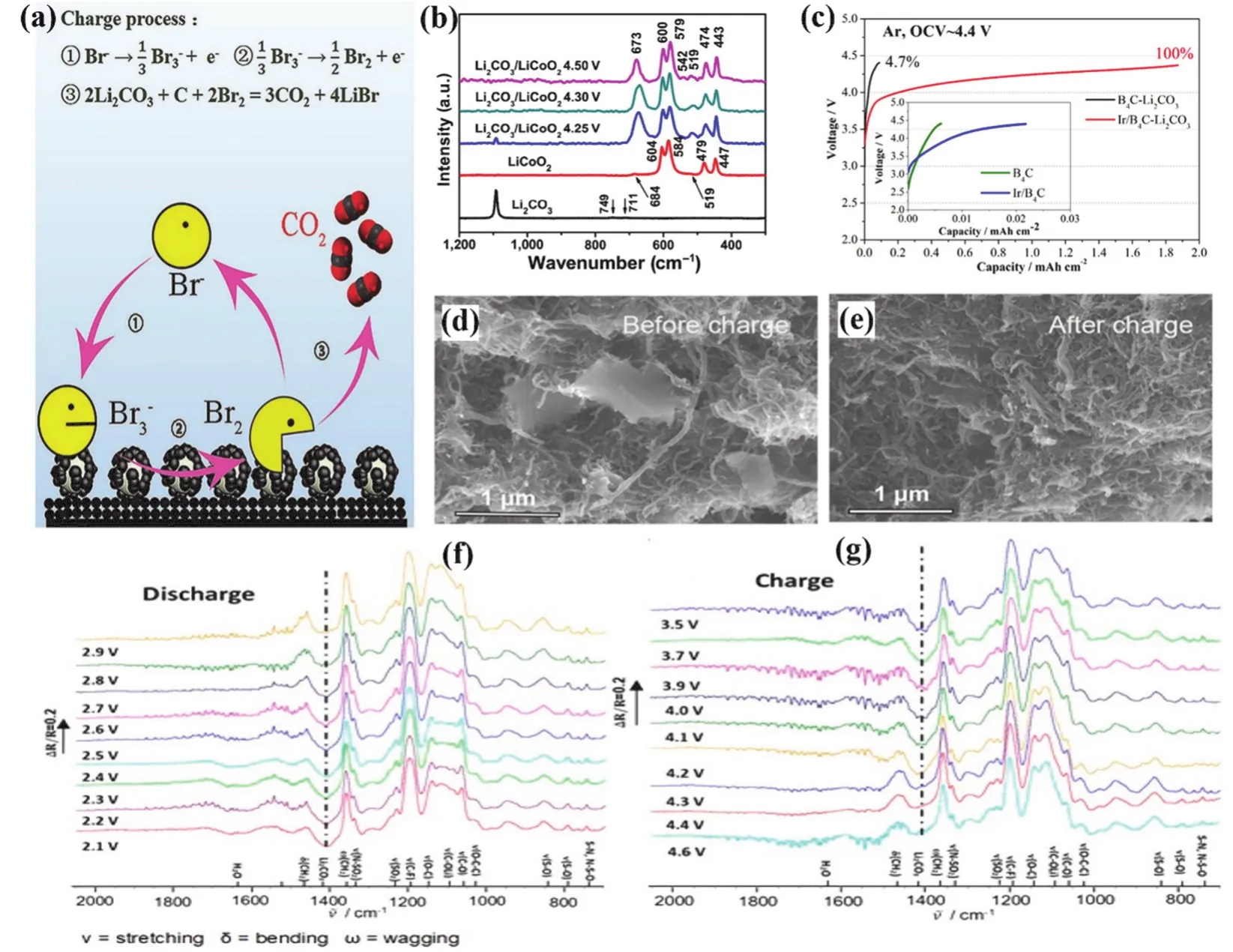
Fig. 6 (a) Proposed mechanism of the charging process with LiBr as the redox mediator in Li-CO2 batteries; (b) Raman spectra of Li2CO3, LiCoO2,and Li2CO3/LiCoO2 composites charged to various potentials; (c) charge voltage profiles of B4C and Ir/B4C-Li2CO3 electrodes in Ar, the inset shows the charge profiles of the bare B4C and the Ir/B4C electrodes without preloaded Li2CO3; SEM images of CNT@RuO2 cathodes with preloaded Li2CO3 at different states (d) before and (e) after charge; in situ FTIR characterization of Ru/NiO@Ni/CNT electrodes during the (f) discharge and (g)recharge process.
The metal oxide catalysts loaded on carbon supports provide excellent catalytic performance for LABs. Honget al.58introduced a nanoporous NiO catalyst into LABs to promote the decomposition of Li2CO3. The carbon nanotube (CNT) electrode loaded with NiO catalyst significantly improves the oxidation efficiency of Li2CO3and the cycle performance comparing with the NiO-free CNT cathode. They suggested that Li2CO3might migrate to nanoporous NiO and decompose on NiO by an oxidation reaction. Then, Fanet al.59found that adding LiCoO2nanoparticles to LABs can effectively reduce the oxidation potential of Li2CO3. It can be seen from the Raman spectra (see Fig. 6b) that when the battery is charged to 4.25 V, the band of Li2CO3(1092 cm−1) becomes very weak. When the battery is charged to a higher potential of 4.3 or 4.5 V, the Raman signal of Li2CO3disappeared, indicating its complete decomposition.This reveals that LiCoO2can reduce the initial decomposition potential of Li2CO3to 4.25 V, which is conducive to improving energy efficiency.
Noble metal-based catalysts have also been used for the construction of air electrode because of their high catalytic activity and stability. An ultrafine iridium coated boron carbide(Ir/B4C) was reported by Songet al.60in 2017. The application of Ir/B4C electrode can decompose Li2CO3at a low charging voltage below 4.37 V (see Fig. 6c). By contrast, only 4.7% of the preloaded Li2CO3was decomposed with pristine B4C cathode,indicating that the synergistic effect of Ir and B4C facilitates the efficient decomposition of Li2CO3,i.e., Ir can furnish excellent catalytic activity for the electrochemical oxidation of Li2CO3,while B4C has the advantages of high chemical and electrochemical stability and excellent conductivity.
In 2019, Bieet al.61introduced RuO2modified carbon nanotube as the cathode to the Li-CO2battery for the first time and realize a highly efficient decomposition reaction of preloaded Li2CO3. CNT@RuO2electrode can decompose most of the prefilled Li2CO3with an efficiency of 93% at 10 mA·g−1and a charging platform voltage of about 3.9 V. SEM images also reveal that there is no bulk Li2CO3remaining in the cathode after charging (see Fig. 6d,e). Most recently, Zhanget al.62reported a carbon nanotube supported Ru/NiO@Ni catalyst(Ru/NiO@Ni/CNT), in which Ru nanoparticles anchored on the surface of core-shell structure NiO@Ni nanoparticles. At a current density of 100 mA·g−1,in situFourier transform infrared spectroscopy (FTIR) was carried out to follow the discharge and charge processes. The spectra exhibit a downward peak at 1408 cm−1, which can be attributed to the formation of Li2CO3(see Fig. 6f). When the charging voltage reaches 4.5 V, the peak of Li2CO3nearly disappears (see Fig. 6g). In brief, the strong synergistic effect of Ru and NiO in the catalyst has played an essential role in the efficient decomposition of Li2CO3.
The strategies discussed above can only mitigate the negative impact of Li2CO3to some extent, and however cannot remove it completely. Due to the intrinsically high decomposition potential of Li2CO3, it is hard to further reduce the charging potential of LABs containing Li2CO3. In addition, whether Li2CO3decomposition reaction is the reverse of Li2CO3formation reaction without causing extra parasitic reactions is still unclear and needs more in-depth studies.
3 Materials for CO2 separation
As shown in the previous sections, CO2in the ambient air could cause serious side reactions in LABs. Current strategies of avoiding Li2CO3formation and promoting Li2CO3decomposition cannot eliminate completely the negative effects of CO2. Under this context, it is desirable to design a CO2-proof membrane to prevent CO2 from entering LABs. In this section,we will summarize some promising materials for CO2separation for LABs.
3.1 MOFs
In the past two decades, metal-organic frameworks (MOFs)have received extensive attention in academia and industry as emerging functional materials. It has the crystal structure that is similar to the regular channel of zeolite, but also a higher specific surface area than conventional porous materials63. MOFs have been widely studied in the field of adsorption and separation of gaseous species due to its adjustable specific surface area, pore size, and skeleton structure64–67.
For the first time, Caoet al.68applied MOFs to the field of LABs. An O2selective membrane for the air cathode was prepared by compounding polydopamine-coated CAU-1-NH2MOF crystals with polymethylmethacrylate (PMMA) (see Fig.7). At a current density of 200 mA·g−1, the battery with the mixed matrix membrane (MMM) showed a discharge capacity of 1480 mA·g−1in air, which is much higher than the battery without the membrane. With a limited capacity of 450 mAh·g−1, LAB with the MMM shows a cycle life of 66 cycles, which is better than the pristine cell. There are two reasons for the significant improvement in the battery performance. First, the PMMA polymeric film is hydrophobic, which greatly reduces the rate at which moisture diffuses from the air into the cell. Then, the functional group ―NH2in the MOF, ―OH in the polydopamine molecule, and the ―C=O in the PMMA preferably interact with and can trap the CO2molecules. As a result, the amount of CO2entering the battery is reduced and the formation of Li2CO3is hindered. This research offered a new approach to develop LABs working in the ambient atmosphere. Although the cell performance was improved, the CO2separation details of the membrane, including flux, permeability, separation coefficient,etc.is still unclear. Moreover, the frequently observed phenomenon that a small amount of CO2in the feed O2gas would increase the discharge capacity has not been observed in this study.

Fig. 7 Schematic illustration of the MMM based on CAU-1-NH2@PDA (PDA:polydopamine) and PMMA polymer for repelling H2O and CO2 molecules in breathing air.
3.2 Amine-modified adsorbents
So far, a variety of amine-modified solid adsorbents have been studied and applied to the capture and separation of CO2 from air69. Amine-modified solid adsorbents are mainly composed of matrixes with highly developed porosity and active sites with high affinity to CO270,71. Solid amine adsorbents have a broad application because of their simple operation process, high efficiency, weak toxicity, low regenerative energy consumption,etc.
Wurzbacheret al.72first combined an amine-functionalized nanofiber cellulose adsorbent (APDES-NFC-FD) with a temperature-vacuum swing (TVS) cyclic process to extract CO2 from ambient air. This cycling process can co-adsorb and desorb H2O and CO2in the air. Therefore, both H2O and CO2from the feed gas of LABs can be removed simultaneously. When the relative humidity of the air increases from 20% to 80% at 20 °C,the CO2 adsorption amount increases from 0.39 to 0.65 mmol·g−1(see Fig. 8a). At a specific adsorption temperature, the relative humidity significantly promotes CO2and H2O adsorption capacities. The adsorbed CO2was desorbed under 5000 Pa at 95 °C and the purity of gas reached 94.4%. In order to test the stability of the adsorption material, 10 continuous adsorption/desorption cycles were carried out (see Fig. 8b). In these 10 cycles, the amount of CO2adsorption and desorption remained steady at 0.415 and 0.421 mmol·g−1, respectively.

Fig. 8 (a) CO2 uptake during adsorption at 20 °C and an air relative humidity of 20%, 40%, 60%, and 80%; (b) specific adsorbed/desorbed amounts of CO2 and H2O in multicycle experiment at 20 °C and an air relative humidity of 40%; (c) schematic illustration of PEI distribution in HP20 resin;(d) the amount of CO2 on HP20/PEI-50 at 25 °C adsorbed from artificial air containing 400 ppm CO2 in five adsorption cycles; (e) breakthrough curves for CO2 as a function of temperature at various feed flow rates of I) 40, II) 60, and III) 90 cm3·min−1; (f) pseudo-equilibrium and breakthrough CO2 capacity under dry and humid adsorption conditions at 35 °C. C0 for CO2 concentration in the feed; breakthrough capacities determined from the breakthrough curves and defined at 5% of C0; pseudo-equilibrium capacities determined from the breakthrough curves and defined at 95% of C0.
Then, Chenet al.73developed a polyethyleneimine (PEI)-impregnated resin which can absorb CO2 from the air efficiently.The adsorbent (HP20/PEI-50) was prepared by loading 50% (w)PEI onto the nonpolar resin HP20. The distribution of PEI in HP20 is shown in Fig. 8c. The pore size range of 43–68 nm plays an important role in the adsorption of CO2, which may facilitate the diffusion of CO2in HP20/PEI-50. Under the condition of 25 °C, HP20/PEI-50 can absorb 99.3 mg·g−1CO2in the artificial ambient air containing 400 ppm CO2and maintain high CO2adsorption capacity in five consecutive adsorption cycles (see Fig. 8d).
Recently, Sujanet al.74functionalized polymer/silica fibers with PEI to produce an adsorbent (PEI-CA-SiO2). This adsorbent can achieve high purity CO2recovery from ambient air under dry and humid conditions. The CO2breakthrough experiments were carried out under these two conditions. The breakthrough time is defined as the time when the CO2 concentration at the outlet rises to 5% of the inlet concentration.Fig. 8e shows the breakthrough curves of CO2under dry conditions. Increasing the intake airflow helps reduce the external mass transfer resistance so that CO2breakthrough time decreases as the function of experimental temperature. As the adsorption temperature increases, the adsorption capacity of this adsorbent also decreases. The CO2breakthrough experiment is then continued under humid conditions with a relative humidity of 85%. The pseudo-equilibrium CO2capacity of this adsorbent increases to 1.6 mmol·g−1in humid conditions, which is about 2.5 times higher than that of 0.59 mmol·g−1under dry conditions(see Fig. 8f). Water vapor leads to the release of more free amino groups, resulting in more carbamate ions, which improves the CO2capacity of the adsorbent75. This kind of adsorbent shows great potential in the field of O2separation from the air.Therefore, it is a promising solution to remove the CO2/H2O from the feed gas of LABs, and moreover the desorbed CO2can be used for other purposes, such as feed gas of the topical CO2electrolyzers.
3.3 Zeolites
Compared with MOF, zeolite is a much cheaper porous material76. Zeolites with medium pore size, such as 5A and 13X,are considered as a kind of promising CO2adsorbents due to their fast adsorption kinetics, good thermal stability, chemical stability, and mechanical stability under low pressures77–80.
Songet al.81modified 5A zeolite utilizing molecular layer deposition (MLD) and coated its surface with a layer of porous TiO2to optimize its pore size. The MLD coating was prepared through a calcination process. The adsorption and separation performance of MLD-modified 5A zeolite was investigated by varying the calcination temperature and calcination residence time (see Fig. 9a). The CO2adsorption capacity of 5A-MLD-250-1min (representing a modified 5A zeolite with calcination temperature of 250 °C and residence time of 1 min) is much higher than that of 5A-MLD-200-2h, which indicates that the organic substances in the MLD coating begin to decompose between 200 and 250 °C (1.79 mmol·g−1and 0.021 mmol·g−1,respectively). At 5 × 10⁵Pa and 25 °C, although the unmodified 5A zeolite has a high CO2adsorption capacity (1.88 mmol·g−1),the CO2/N2selectivity is only 19. In contrast, 5A-MLD-250-2h exhibits a high CO2/N2selectivity of 74 and a high CO2adsorption capacity of 1.79 mmol·g−1. After one minute of adsorption, the amount of CO2adsorption reaches 90% of its equilibrium amount, only 20 s slower than 5A zeolite, and the adsorption rate is fast (see Fig. 9b). This research was carried out with flue gas, and the concentration of CO2was relatively high.Whether it can effectively adsorb CO2in the ambient air with a low concentration of 300–400 ppm CO2needs to be further explored.

Fig. 9 (a) CO2 (left y-axis; black column) adsorption capacity and CO2/N2 adsorption selectivity (right y-axis; red column) at 50 Pa and 25 °C on the 5A and MLD-coated 5A zeolite calcined at different conditions and (b) CO2 adsorption kinetic uptake curve on the 5A zeolite (black symbol) and 5A-MLD-250-2h (red symbol).
So far, the research on CO2-proof membranes used in LAB systems is just at the beginning. Many CO2adsorbent materials have not yet been studied in the context of LABs. The concentration of CO2in breathing air is so low that it would challenge the present gas separation materials and protocols. In the reported studies of the CO2-proof membranes used in LABs,no details of CO2separation have been provided. Since the molecular kinetic radius of CO2is smaller than that of O2, it will be difficult to exclude CO2by employing a size-control mechanism to realize the priority of O2going through the membrane. Developing new separation materials to optimize the selectivity of O2/CO2and remove the negative effects of CO2on LABs will be an arduous but a rewarding task.
4 Conclusions
Removing the negative effects of CO2is a threshold that must be addressed before LABs could move from laboratory to market. In the last two decades, we have witnessed significant advances in LABs. These progresses benefit from mechanistic understanding by advancedin situcharacterization techniques.For instance, the spectroscopic identification of the C2O62−intermediate in discharge reaction of LABs operated in the O2/CO2atmosphere inspired rational regulation of electrolyte composition and thus avoided the formation of Li2CO3. The discovery of singlet O2explained the missing of O2upon Li2CO3decomposition and inspired researchers to develop more stable electrolytes. However, the CO2-induced parasitic chemistry is still not completely understood, and the minimum concentration of CO2allowed in the LABs is still unknown. In the future, it is necessary to develop and employ more advancedin situspectroscopic technologies to systemically examine the reactions and processes occurring at the cathode/electrolyte interface,i.e.how the catalysts affect the O2electrochemistry in the presence of low concentration CO2. These fundamental understandings will help design better catalysts and electrolytes and achieve LABs electrochemistry in a controllable manner.
In addition to the understanding of the reaction mechanisms of LABs, preventing CO2from entering LABs is also a viable(maybe ultimate) strategy, for example, by using CO2-proof membranes. Although many CO2adsorbents have been developed, they have not been tested in the LABs yet. It is expected that these materials can be applied to the open LAB system. However, the development of room-temperature O2-permeable membranes with high selectivity for CO2still faces significant challenges. The separation membrane is not just as simple as a filter paper. In fact, there is a dynamic competition process of various molecules in the feed gas and the performance of the membrane is influenced and even dominated by many experimental conditions, such as gas flow rate, pressure drop, the concentration of CO2, impurities in the gas,etc. More chemical engineering efforts are required to couple the O2 purification system with the LABs.
In summary, it is vital to understand the CO2-induced parasitic chemistry and remove CO2from the breathing air before a truly LAB can be realized. If other challenges associated with LABs can also be solved, the current energy storage will be transformed and the impact on the contemporary and future society will be immense.
猜你喜欢
大众文艺(2022年21期)2022-11-16
今日农业(2022年14期)2022-09-15
昆明理工大学学报(自然科学版)(2022年4期)2022-09-07
军事文摘(2022年14期)2022-08-26
新少年(2022年3期)2022-03-17
渤海大学学报(自然科学版)(2021年3期)2021-12-27
幼儿画刊(2021年9期)2021-09-20
现代企业(2021年2期)2021-07-20
幼儿画刊(2020年7期)2020-09-11
共产党员·上(2020年6期)2020-07-04
