
Two-color laser PEEM imaging of horizontal and vertical components of femtosecond surface plasmon polaritons
2022-10-26 09:51ZhenLongZhao赵振龙BoYuJi季博宇LunWang王伦PengLang郎鹏XiaoWeiSong宋晓伟andJingQuanLin林景全
Chinese Physics B 2022年10期
Zhen-Long Zhao(赵振龙), Bo-Yu Ji(季博宇), Lun Wang(王伦), Peng Lang(郎鹏),Xiao-Wei Song(宋晓伟), and Jing-Quan Lin(林景全)
School of Physics,Changchun University of Science and Technology,Changchun 130022,China
Keywords: femtosecond surface plasmon polaritons,two-color photoemission electron microscopy,near-field imaging
1. Introduction
Surface plasmon polaritons (SPPs) are electromagnetic waves transmitted at the metal–dielectric interface with a speed near that of light and are capable of subwavelength localization via metal nanostructures.[1,2]Signal processing applications[3–5]are made possible by these remarkable properties. An accurate near-field imaging of the SPPs field is a prerequisite for the precise application of SPPs. At present,the techniques used for near-field imaging of SPPs include near-field scanning optical microscopy,[6]cathodoluminescence microscopy,[7,8]fluorescence microscopy,[9,10]electronic energy loss microscopy,[11,12]and photoemission electron microscopy(PEEM).[13–15]Among them,PEEM can resolve SPPs with high spatial resolution without the use of molecular reporters and scanning probes as required in nonlinear fluorescence microscopy[9]and scanning near-field optical microscopy,[16]respectively, which makes PEEM a powerful tool for the investigation of SPPs. Crucially, due to specific boundary conditions, SPPs is essentially transverse magnetic wave with vertical and horizontal electric field components in the propagation plane.[17]The horizontal and vertical components of the SPPs field have different functionalities for different application areas. For instance,it has been shown that the vertical component of SPPs dominated the two-dimensional plasmonic lens focusing performance and the pure SPPs interference pattern,[18–20]while the horizontal component of the SPPs field is more significant in the SPPs super focusing by a metallic cone.[21,22]Hence, distinct and independent imaging of vertical and horizontal components of the SPPs field with PEEM is necessary.
Several potential solutions have recently been proposed for imaging the vertical and horizontal components of SPPs field, including the utilization of the scanning near-field microscope[23,24]and photoemission electron microscope.[25–27]Specifically, Podbiel and co-workers visualized the horizontal field component of SPPs via the interference patterns generated from the interaction between incident laser and SPPs using normal-incidence PEEM.[26]However,due to the absence of the electric field component vertical to the sample surface for the probe laser, the observation of the vertical component of SPPs is prohibitive in that case.Qin and co-workers[27,28]achieved independent spatiotemporal imaging of vertical and horizontal components of the SPPs field with obliquely incident one-color TR-PEEM. However,to capture the weak horizontal component of the SPPs field,a relatively harsh experimental condition is indispensable for that scheme. First,the silver sample,which has a lower work function than the other precious metals, is utilized in that experiment to obtain enough PEEM image brightness of the SPPs, but the easily oxidized and chemically unstable characters of the silver material strongly restrict its application.Secondly,the specified polarization angle(fixed at 45°,for the directional excitation of the SPPs field to increase the intensity of the SPPs at a certain direction) and relatively higher power of the femtosecond laser are needed simultaneously to provide enough brightness of the PEEM image of SPPs. As a result, the experiment was carried out at the risk of the potential damage to the sample and also at the expense of SPPs field information loss due to the limitation in the launching direction of SPPs.
In this paper, to overcome the limitation of our previous experiments with one-color PEEM,we carried out the distinct imaging of the vertical and horizontal components of SPPs launched from a trench with the 400-nm laser-assisted nearinfrared(NIR)femtosecond laser TR-PEEM imaging technology (two-color laser PEEM technology). The pump–probe setup consists of two spatially separated 800-nm laser beams,where the pump laser is p-polarized and the probe laser is p/spolarized to visualize different components of SPPs. Additionally, the 400-nm pulse with different polarization directions is used to enhance the photoemission yield for better visualization of interference fringes caused by the interaction of the 800-nm probe light with the SPPs. Experiments demonstrate that an introduction of the 400-nm pulse in the spatially separated TR-PEEM scheme allows distinct visualization of the different components of the SPPs field,accompanying with circumventing the risk of sample damage as well as the shortcoming of information loss of the excited SPPs field that is generally confronted in the usual spatially separated one-color IR laser TR-PEEM scheme. The underlying mechanism responsible for realizing distinct visualization of the different components of the SPPs field by two-color PEEM is revealed by obtaining the measurements of the double logarithmic dependence of photoemission yield with the 800-nm and 400-nm pulse powers of different polarizations. Moreover, we found that the PEEM image quality of the vertical and horizontal components of the SPPs field is nearly independent of the polarization of the 400-nm pulse which suggests the robustness of this two-color scheme.Our results pave a way for the application of the different components of the SPPs near field and offer help for drawing the SPPs field in the three-dimensional spatial-temporal domain.
2. Experimental setup
A rectangular 20 μm×1 μm trench coupling structure was milled into a 120-nm thick gold thin film using focused ion beam lithography. The inset of Fig.1 displays the topography of the trench structure imaged with PEEM under Hg lamp illumination. Femtosecond laser pulses(76-MHz repetition rate)were generated by a commercial titanium–sapphire femtosecond oscillator(Coherent,Mira 900)with a central wavelength of 800 nm (150-fs pulse width). Aβ-BaBO3(BBO) crystal was used for generating the second harmonic 400-nm pulse.The 800-nm pulse and the 400-nm pulse are focused onto the sample surface through two flanges of the PEEM with an incident angle of 65°relative to the surface normal. The corresponding attenuation plates and half-wave plates for 800-nm and 400-nm pulses were used for independently adjusting their power and polarization angle, respectively. The elliptically shaped spot size of the red light is 50 μm×25 μm, and the elliptically shaped spot size of the blue light is twice as large as that of the red light at the sample position. A schematic diagram of the two-color experiments is shown in Fig.1. The PEEM is utilized to directly image the interference patterns of the SPPs near-field by collecting photoelectrons emitted from the sample surface. The SPPs were excited by a p-polarized 800-nm pump pulse,which is detected at a remote position by the 400-nm (p/s)-assisted p/s-polarized 800-nm probe pulse.kLandkSdenote the wave vectors of the in-plane incident light and SPPs. Meanwhile, the laser power of the 800-nm pump/probe pulse is 150 mW and 30 mW–120 mW, respectively,while the 400-nm pulse laser power is 3 mW–14 mW.
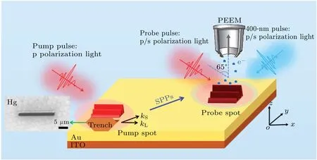
Fig.1. Schematic diagram of the two-color setup. The inset photo in the figure shows the topography of the sample under Hg lamp illumination.
3. Results and discussion
Figure 2(a) depicts the photoemission interference patterns obtained with monochromatic 800-nm pump–probe pulses. A p-polarized pump laser at 800-nm excited the SPPs,which were detected by the 800-nm p-polarized probe laser at a distance of about 80 μm from the coupling structure. The time that the SPPs and the probe pulse overlap in space is defined as zero delays. The bottom of Fig.2(a)is a vector figure of the laser and SPPs field. Figure 2(a) clearly demonstrates that we have imaged the vertical component of the field of SPPs through a p-polarized 800-nm probe laser. Figure 2(b)shows the photoemission interference patterns under the same delay time except for the probe pulse is 800-nm s-polarized.It shows that the interference patterns generated from the spolarized 800-nm probe light and the SPPs field are hardly recognized, and accordingly, the spatiotemporal information of the horizontal component of the SPPs field cannot be captured in this one-color PEEM scheme. This result could be attributed to the following reasons. (i) The work function of gold we used in this experiment is higher than that of silver used in our previous research in which a 3-photon photoemission was realized and independently imaging of vertical and horizontal components of SPPs had been successfully achieved only by one-color 800-nm laser PEEM.[28]However,a higher 4-photon nonlinear order(4PP)is required in the current gold sample, resulting in fewer photoelectrons for SPPs imaging. Moreover,it is known that the intensity of the horizontal component of the SPPs field(ES.Hin Fig.2(a))is much smaller than the vertical component of the SPPs field (ES.Vin Fig.2(a)),[28]which results in insufficient photoemission to meet the needs of PEEM imaging for the horizontal component of the SPPs being captured while the vertical component of SPPs field can be captured as shown in Fig.2(a). (ii)In our previous experiment for spatiotemporal imaging of the vertical and horizontal components of the SPPs field, the pump pulse with a polarization angle of 45°off the main axis of the sample is used to directionally excite the SPPs towards one side of the trench to facilitate the nonlinear multiple photon photoemission imaging of the SPPs field. As a result, the previous scheme is at the expense of information loss of the SPPs field at the opposite side of the trench. In the current scheme of SPPs field excitation from the trench,we do not intend to set a special polarization direction of the pump pulse like the previous experiment[27,28]which can launches SPPs on both sides of the trench, it gives more freedom to exploit the polarization direction of the pump pulse and thus offers more opportunity for SPPs applications such as multiplexing devices.[29]To avoid CCD saturation from localized surface plasmon excitation on the edges of the groove, we removed the groove structure from the field of view of the PEEM image.
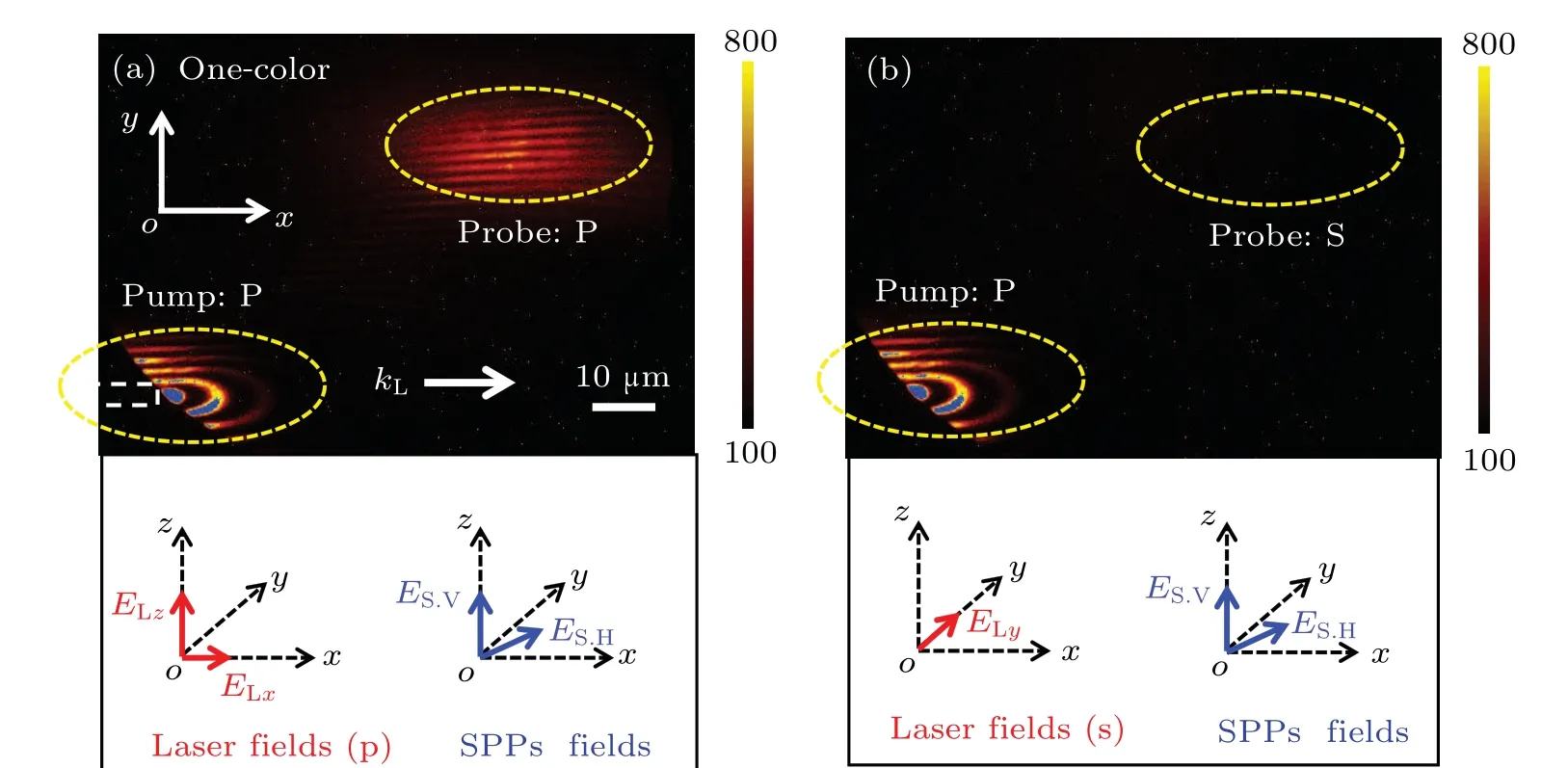
Fig. 2. One-color photoemission interference patterns of the spatially separated pump–probe experiment at a 20 μm×1 μm trench structure. PEEM image was obtained with(a)p-polarized and(b)s-polarized probe pulses,respectively. The white dashed rectangle represents the trench location,and the yellow dashed ellipse represents the approximate location of the spatially separated pump and probe pulses.
To fully capture the SPPs field components from the trench structure in the gold film sample, a two-color laser PEEM scheme as shown in Fig. 1 has been employed in the following investigation. In the two-color scheme,a femtosecond laser at 400-nm wavelength is united with the probe pulse at 800-nm wavelength for imaging the SPPs field. Figure 3(a)shows the PEEM images obtained with an 800-nm p-polarized pump pulse and an 800-nm p-polarized probe pulse assisted by a 400-nm p-polarized one. In comparison to the results of the one-color experiment shown in Fig. 2(a), the interference fringes measured with two-color PEEM appear the same but with an enhancement of photoemission yields. Importantly,Figure 3(b)shows the PEEM image followed by an s-polarized 800-nm probe laser assisted with a p-polarized 400-nm laser in the probe area. It displays that in the probe area, the spolarized 800-nm pulse interacted with the SPPs field,resulting in clear interference fringes. As a result of the superposition of the horizontal field component of SPPs and the probe pulse, interference patterns can be seen in the probe area of Fig. 3(b), and the relevant vector figure of the laser field and the SPPs field refer to the one at the bottom of Fig.2(b). The interference fringes in Fig. 3(b) indicate that the horizontal component of the SPPs has been successfully captured. To confirm the success in the visualization of the horizontal and vertical components of the SPPs field in our case,we measured the interference fringe drift between the two components of theE-field captured by the s-polarized and p-polarized probe lasers. Experimental results show that the peak spacing of the interference fringes with p- and s-polarized probe pulses are always ΔS/4 (The value of ΔSis 1.6 μm in the PEEM image), indicating the phase delay between the horizontal and out-of-plane components corresponding to theπ/2 phase difference.[17]Therefore, the horizontal and vertical components of the SPPs field are successfully imaged in this twocolor PEEM scheme with noncollinear excitation mode. In short,we have distinctly captured the spatiotemporal information of the horizontal component of the SPPs field using the s-polarized probe pulses with the two-color PEEM.
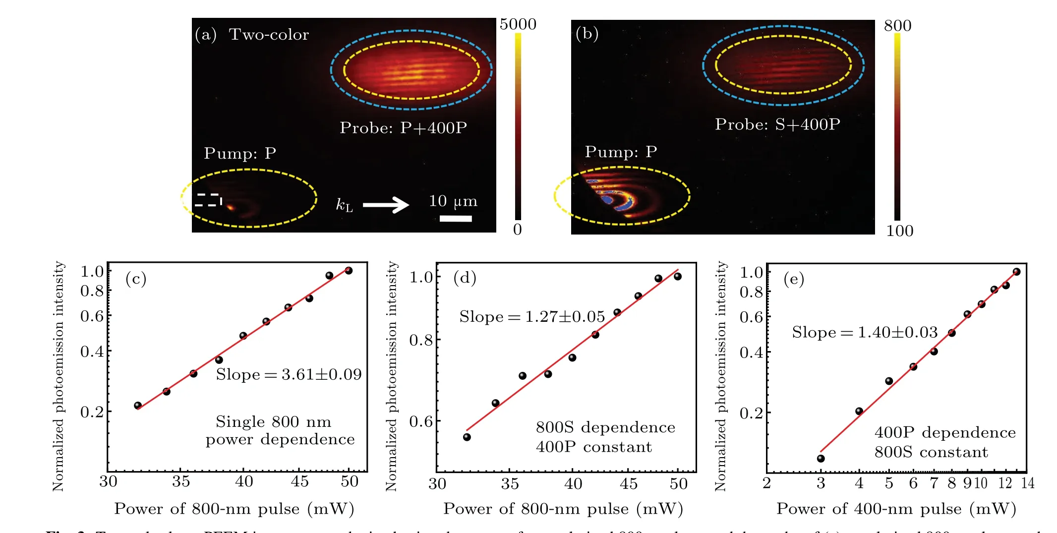
Fig.3. Two-color laser PEEM images were obtained using the pump of a p-polarized 800-nm laser and the probe of(a)p-polarized 800-nm laser and(b)s-polarized 800-nm laser,respectively. The approximate location of the 400-nm pulse is indicated by the blue elliptical dashed ellipse. The double logarithmic dependence of photoemission yield with the single 800-nm laser power(c),with the s-polarized 800-nm laser power after introducing the 400-nm laser pulse(d),and with the 400-nm laser power(e). In measuring the dependence of power on photoemission yield,the photoemission yield induced by the unchanged laser is deduced.
It is interesting to note that the vertical field component of the SPPs field induces a far stronger photoemission intensity than those induced by the horizontal component.This is due to the reason we discussed above: the vertical component of the SPPs field amplitude is much larger than that of the horizontal component.[28]Moreover, due to Fresnel’s law of refraction,the SPPs propagation direction has a certain angle with theyaxis, as shown in Fig. 1, and only the projection of the horizontal component of SPPs onto theyaxis can interfere with the 800-nm s-polarized probe laser. Therefore,the above two factors determine the difference in photoemission intensity of the interference fringes corresponding to horizontal and vertical components. It needs to be mentioned that the value of the color bar is fine-tuned with different starting values in Fig. 3 to enhance the visibility of the interference signal.
As shown in Figs. 3(a)–3(b), the assistance of a 400-nm laser in the detection location plays a significant role in the realization of distinct spatiotemporal visualization of vertical and horizontal components of the SPPs field. To analyze the underlying physics mechanism for realizing distinct spatiotemporal visualization of the two components of the SPPs field in this two-color laser PEEM scheme, we obtained the double logarithmic dependence of photoemission yield with the laser power(for 800-nm and 400-nm pulses,respectively)under one- and two-color cases as shown in Figs. 3(c)–3(e).Figure 3(c)shows the double logarithmic dependence of photoemission yield with the one-color 800-nm laser power. It is found that the slope value of the photoemission yield plot is about 3.61,indicating at least four 800-nm photons are needed to emit from the gold surface (corresponding to a 4-photon photoemission process). It needs to mention that in our onecolor 800-nm pulse power dependence measurement,since the s-polarized 800-nm pulse alone as probe light cannot induce enough photoelectrons to satisfy PEEM imaging, we choose the p-polarized 800-nm pulse case to reveal the nonlinear order of the photoemission process. Figure 3(d) shows the double logarithmic dependence of photoemission yield with the 800-nm s-polarized pulses with the presence of a-3-mW 400-nm laser. It can be seen that the nonlinear order of the photoemission yield dependence on the 800-nm laser power under this two-color case decreases from nearly 4 to a value of 1.27. Figure 3(e)shows the double logarithmic dependence of photoemission yield with the 400-nm laser pulses with the constant power of the 800-nm s-polarized pulse and corresponds to a slope value of 1.40. Figures 3(c)–3(e) shows that the nonlinear order of the photoemission is changed from four to nearly three(one 400-nm photon with two 800-nm photons)with the help of 400-nm light. The reduction of photoemission nonlinear order corresponds to an effective opening of the twocolor quantum channel for photoemission.[30,31]Specifically,in single-color pulse excitation at 800 nm, the localized electrons near the Fermi level of gold will be stimulated,via intermediate states, to form photoelectrons by simultaneously absorbing 4 photons of 800-nm laser.In this case,the photoemission yield followsP∝E8z, whereEzrepresents thezcomponent of the electric field derived from the 800-nm laser illumination. The photoemission induced by a two-color excitation can absorb photons of different colors simultaneously.[31]As a result, the dependence of photoelectron yield onEz@800 nm is dramatically reduced toP∝E4z. More importantly, due to the introduction of the 400-nm pulse,more possible quantum channels emerge for the ejection of photoelectrons accompanied by a decrement of the nonlinear order and an increasement of the photoemission yield.[32,33]The reduction of the nonlinear order of photoemission is accompanied by a great enhancement of the photoelectrons yield that is essential for readily imaging the horizontal component of the SPPs field via the two-color scheme.
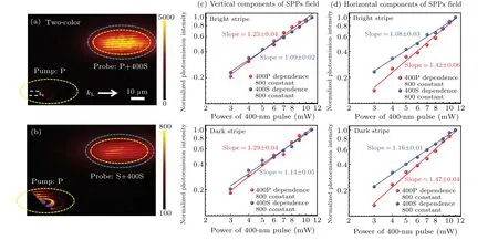
Fig.4. Two-color PEEM image was obtained with the probe of(a)p-polarized and(b)s-polarized 800-nm lasers assisted by s-polarized 400-nm pulses.The double logarithmic dependence of photoemission yield with the 400-nm p-polarized and s-polarized laser powers from the bright and dark fringes corresponding to(c)the vertical and(d)the horizontal components of the SPPs. During recording,the power of the 800-nm laser pulse was fixed.
The polarization angle of 400-nm light was further investigated on the photoemission interference patterns of the horizontal and vertical components of the SPPs field. To this end,we turned the polarization direction of the 400-nm laser from p-polarized laser pulse to s-polarized laser pulse. Figures 4(a)and 4(b)shows the photoemission interference patterns under 800-nm p-polarized and s-polarized probe pulses assisted with 400-nm s-polarized laser pulse. As far as we know the absorptivity of the gold film will vary with different polarization directions of 400-nm laser for oblique incidence. To exclude this influence,we utilized the same effective absorption power by considering the absorptivity of the gold material on the 65°obliquely illuminated 400-nm laser with different polarization angles. Compared with the results obtained with 400-nm ppolarized laser pulse as illustrated in Figs. 3(a) and 3(b), the interference patterns under 400-nm s-polarized laser illumination as shown in Figs. 4(a) and 4(b) are consistent except for the enhanced photoemission yield of the SPPs interference fringes.
We extracted the photoelectron yields in the same region under the 400-nm p-polarized and s-polarized pulses,respectively,with the polarization of the 800-nm pulse kept unchanged (either p-polarized for the vertical component or spolarized for the horizontal component of SPPs field). The results showed that,for the p-polarized 800-nm laser probe case,the photoelectron yields were 67829(for p-polarized 400-nm laser case) and 116184 (for s-polarized 400-nm laser case),respectively, showing a nearly 1.71 times photoelectron enhancement for an s-polarized 400-nm pulse over a p-polarized 400-nm pulse. When the probe pulse was 800-nm s-polarized pulse, the photoelectron yields were 24330 (for p-polarized 400-nm laser case) and 38140 (for s-polarized 400-nm laser case),respectively,corresponding to a photoelectron yield enhancement of about 1.56 times. The above results show that the brightness of the interference fringes under s-polarized 400-nm laser illumination is higher than that under p-polarized 400-nm laser illumination for both the vertical and horizontal components of the SPPs field.
Further, for exploring the reason for the higher brightness of the interference fringes under the assistance of spolarized 400-nm light than that of the p-polarized case, we measured the 400-nm pulse power dependence of the photoelectron yields from bright and dark fringes when the 800-nm probe pulse is p/s-polarized, respectively, and the results as shown in Figs.4(c)and 4(d). Figure 4(c)displays the double logarithmic dependence of photoemission yield with the 400-nm laser power from bright and dark fringes with the fixed p-polarized 800-nm probe pulse which represents the vertical component of the SPPs. It can be seen that the slope values of the photoelectrons from bright and dark stripes are 1.23 and 1.29, respectively, for the p-polarized 400-nm case, and then decrease to 1.09 and 1.14 with the polarization of the 400-nm laser being adjusted to s-polarized one. As we discussed above,the lower the nonlinear order of the photoemission, the higher the photoelectrons yield is. Moreover, it has been shown that under two-color femtosecond laser excitation,the photoemission electrons can eject through two-color quantum channels.[33,34]When the two-color quantum channel is opened to a greater degree, the nonlinear order of photoelectrons will be dramatically reduced, resulting in a significant increase in photoemission yields.[31]Consequently,the photoelectron yields at the bright and dark fringes of the SPPs field interference fringes with the help of 400-nm s-polarized pulse illumination is higher than that with the 400-nm p-polarized pulse owing to a greater open degree of the two-color quantum channel. Figure 4(d) depicts the double logarithmic dependence of photoemission yield with the 400-nm p-polarized and s-polarized laser powers from bright and dark fringes when the s-polarized 800-nm probe pulse is used. Likewise,the nonlinear orders of the photoemission at the bright and dark fringes of the interference fringes corresponding to the horizontal component of the SPPs field are lower and corresponding to a higher photoemission yield under the 400-nm s-polarized laser case than that of the p-polarized 400-nm laser case. The above results show that when s-polarized 400-nm light is used to assist in imaging the horizontal and vertical components of the SPPs field, the nonlinear orders of the photoemission at the bright and dark fringes are lower,corresponding to an enhanced photoemission yield and brighter interference fringes.
It is important to emphasize that although the photoelectron yield of the interference fringes of the SPPs field is higher when s-polarized 400-nm laser light illumination, it does not mean a better visualization of the PEEM image at this time.Because the contrast of the bright and dark interference fringes of the SPPs field is the fundamental standard to evaluate the imaging effect of the SPPs field. Thus,to evaluate the PEEM image’s visibility, the contrast of SPPs interference fringes under 400-nm light in different polarization cases are taken into consideration simultaneously. The contrast is obtained by extracting the photoemission yield of the adjacent bright and dark fringes when the 400-nm light is p/spolarized. The calculation results show that the interference fringes contrast of the vertical and horizontal components of the SPPs field are 1.25 and 1.20, respectively for the p-polarized 400-nm laser case. When the 400-nm light is turned into s-polarization,the contrast of the vertical and horizontal components of the SPPs field are 1.19 and 1.20, respectively. The above results show that the contrast of the interference patterns corresponding to the vertical and horizontal components of the SPPs field is nearly the same for the two polarization directions of the 400-nm laser.No big change in the contrast can be explained as the following. Changing the 400-nm pulse from p-polarization to s-polarization reduces the nonlinear order of the photoemission significantly at both the bright and dark stripes. Increasing the photoelectron yield at the dark and bright fringes at the same time results in almost no change in the contrast of the fringes. In short,the above results show that the polarization direction of the 400-nm light shows a negligible effect on the imaging contrast of the horizontal and vertical components of the SPPs field even though it affects the brightness of the PEEM images. Thus, the independence of the 400-nm laser polarization angle on the contrast offers the robustness of the 400-nm laser pulse assisted PEEM experiment on disclosing the horizontal and vertical components of the SPPs field. Furthermore, it can be noticed from Figs. 4(b) and 4(c) that the slope value corresponding to the bright fringe is lower than that of the dark fringe. It is attributed to a stronger 800-nm light intensity for the bright fringes due to the constructive interference and accordingly a stronger interaction between 400-nm and 800-nm lasers. As a result, the bright fringe corresponds to a greater open degree of two-color quantum channel than the dark fringe. Since the light intensity associated with bright and dark fringes has a different spatial distribution,the open degree of the two-color quantum channel also varies spatially.
4. Conclusions
In summary, we demonstrated the independent, spatiotemporal visualization of the vertical and horizontal components of SPPs launched from a rectangular trench with a 400-nm laser-assisted TR-PEEM.It is found that an introduction of the 400-nm laser pulse allows distinct imaging of the two different components of the same SPPs field without the risk of sample damage as well as the problem of information loss of the excited SPPs field that is generally confronted in the usual spatially NIR laser TR-PEEM scheme. Our experimental results essentially showed that the vertical and horizontal components of the SPPs field can be imaged no matter whether the 400-nm pulse is p-polarized or s-polarized,showing the robustness of the introduced 400-nm pulse in the experiment. The underlying mechanism for realizing distinct imaging of the different components of the SPPs field is revealed by measuring the power dependence of the 800-nm light and 400-nm light with different laser polarization directions. With the help of the two-color NIR laser time-resolved PEEM scheme,we have comprehensively captured spatiotemporal information of the horizontal and vertical components of the SPPs near-field from the noncollinear mode, and offer a possible solution for drawing the SPPs field in the three-dimensional spatial-temporal domain.
Acknowledgements
Project supported by the National Natural Science Foundation of China (Grant Nos. 62005022, 12004052,and 62175018), the Fund from Jilin Provincial Key Laboratory of Ultrafast and Extreme Ultraviolet Optics(Grant No. YDZJ202102CXJD028), Department of Science and Technology of the Jilin Province, China (Grant Nos. 20200201268JC and 20200401052GX), the “111”Project of China(Grant No.D17017), and the Fund from the Ministry of Education Key Laboratory for Cross-Scale Micro and Nano Manufacturing, Changchun University of Science and Technology.

- Chinese Physics B的其它文章
- Formation of high-density cold molecules via electromagnetic trap
- Dynamics of molecular alignment steered by a few-cycle terahertz laser pulse
- Terahertz spectroscopy and lattice vibrational analysis of pararealgar and orpiment
- Molecule opacity study on low-lying states of CS
- Finite-time Mittag–Leffler synchronization of fractional-order complex-valued memristive neural networks with time delay
- Ultrafast Coulomb explosion imaging of molecules and molecular clusters