
Bound states in the continuum in metal–dielectric photonic crystal with a birefringent defect
2022-10-26 09:49HongzhenTang唐宏珍PengHu胡鹏DaJianCui崔大健HongXiang向红andDezhuanHan韩德专
Chinese Physics B 2022年10期
Hongzhen Tang(唐宏珍) Peng Hu(胡鹏) Da-Jian Cui(崔大健)Hong Xiang(向红) and Dezhuan Han(韩德专)
1Department of Physics and Chongqing Key Laboratory for Strongly Coupled Physics,Chongqing University,Chongqing 401331,China
2Chongqing Key Laboratory of Core Optoelectronic Devices for Quantum Communication,Chongqing Optoelectronics Research Institute,Chongqing 400060,China
Keywords: bound state in the continuum,birefringence,metal–dielectric photonic crystal,interference
1. Introduction
Light localization is exceedingly important for many applications such as lasing, sensing, and guiding.[1–3]Usually light can be localized by physical confinement via reflection mirror or by total internal reflection due to the momentum mismatch. In these situations there are no radiation channels for the light waves thus no radiation leakage happens. On the other hand, in open systems with accessible radiation channels, it is still possible to realize perfect spatial confinement of light. The bound states in the continuum (BICs) are such states with the frequencies lie in the spectrum of the continuum while the field profiles remain perfectly localized,hence the name. This counterintuitive concept was first proposed by Von Neumann and Wigner dealing a quantum system with artificial potential.[4]To date plenty of schemes for BICs have been proposed and experimentally verified in a variety of wave systems.[5–13]In recent years,due to the flexibility of designment and the facility of fabrication,and more importantly,the promising potential applications, BICs in photonic systems have attracted extensive interest and plenty of works for BICs have been reported.[11,14–22]There are two basic mechanisms for BICs. One is the symmetry or polarization incompatibility of the guided mode and the external radiation, and the other one is the complete destructive interference between the radiations of the coexisting resonances in the system. The former type is named symmetry protected(SP)BIC and the latter type is named Friedrich–Wintgen(FW)BIC.[11]
In one-dimensional (1D) systems, defects can be introduced to realize BICs. For example, an obstructing plate placed at the center of an acoustic waveguide can help to achieve SP BICs.[23]Similarly,a coupled photonic waveguide system with two defects placed symmetrically above and below can also support SP BICs.[24]In such systems,the single defect state lies in the spectrum of the continuum states, but the symmetry of the former is different with that of the latter,with one odd and one even. FW BICs due to complete destructive interference can also be induced with the presence of defects. The so-called Fabry–P´erot BIC is realized in a semiinfinite coupled waveguide array,in which the outgoing waves from a defect waveguide and its mirror image with respect to the end make a complete destructive interference and give rise to a bound state.[25]
In recent years,the photonic crystals(PhCs)have become an active platform for BICs and related researches due to the designable band structures and the simplicity of fabrication.In the PhC slabs interference between different guided resonances can readily happen due to the periodic perturbation,and hence FW BICs can be formed easily. However, in the regular 1D layered PhCs, such interference is absent since the eigenmodes for the transverse electric(TE)and transverse magnetic(TM)polarizations are decoupled,and consequently BICs especially the FW BICs are not supported. Here the TE and the TM modes refer to the light waves with electric field perpendicular and parallel to the plane determined by the wave vector and the normal of the PhC layers, respectively. However, BICs can still be constructed by introducing defect into the system. For example, when an anisotropic defect layer is introduced into the 1D layered PhCs, the formerly decoupled waves with orthogonal polarizations will be mixed and interference can take place hence BICs can be realized.[26–28]Based on this idea, Sadreevet al.proposed to realize BICs in a 1D layered PhC with an anisotropic defect layer.[29]The BICs are generated at the vicinity of the Brewster angle,which corresponds to the allowed band of the TM wave and the band gap of the TE wave. The TE wave is naturally trapped in the defect layer due to the polarization incompatibility. The leakage of TM wave is eliminated by the destructive interference between its ordinary and extraordinary wave components in the anisotropic layer.
Different with the above mentioned dielectric PhCs,for a metal–dielectric photonic crystal (MDPhC), there is no welldefined Brewster angle and hence no distinct band structure difference for the TE and TM waves as that in dielectric PhCs.However,below the light line of the dielectric,the plasmonic modes are supported only for the TM polarization. With this band structure difference for the TE and TM waves, the scheme mentioned above can be adopted to the MDPhCs to achieve BICs.
In this paper, we investigate the BICs formed in a 1D MDPhC system with an embedded birefringent defect layer(BDL).With the polarization selection of the plasmonic modes and the polarization mixing of the embedded BDL,the bound states localized in the BDL are formed in the continuum of plasmonic modes. Both the SP and FW BICs are achieved in this system with the rotation of the BDL.A modified scheme for the practical realization is also considered and verified numerically. This scheme provides a generic method to achieve BICs in the 1D MDPhC systems.
2. Results and discussion
The system under study consists of two symmetrically placed MDPhC segments and a BDL sandwiched between them, as shown in Fig. 1(a). Theoretically, the two MDPhC segments should be semi-infinite long. For the MDPhCs, the thicknesses of the dielectric layer and the metal layer are respectively denoted astdandtm,and the corresponding permittivities areεdandεm,respectively. Hereεmis described by the Drude-type model:ε(ω)=1-ω2p/(ω2+iγω), whereωpis the plasma frequency andγis the collision frequency. The optical axis of the BDL lies in thex–yplane and makes an angle ofφwith respect to theyaxis,as suggested in Fig.1(b). The length of the BDL isLand the two principle values of the refractive indexes areneandno,withneandnofor polarizations parallel and perpendicular to the optical axis,respectively.
As this system consists of two kinds of medium,the MDPhCs and the birefringent crystal,there are two sets of normal modes that maintain their polarization states in the propagation. For the MDPhCs,the normal modes are the TE and TM waves. For the birefringent crystal,the normal modes are the ordinary (o) waves and extraordinary (e) waves. When the MDPhCs and BDL are combined to form the system under study,the normal modes and hence the polarization states can be mixed.
The band diagrams for the MDPhCs have been investigated before[30]and can be indicated by the transmission spectrum. Figure 1(c)shows the numerically calculated transmission spectra of the TE and TM waves through a 10-period MDPhC segment. The finite element method is applied in this work to perform the numerical calculations. In the calculation,the metal is set as silver[31]withωp=9.38×10¹⁵rad/s and the loss is neglected here. The thickness of the metal layers istm=c/2ωp= 15.95 nm withcthe speed of light in the vacuum. The parameters for the dielectric layers are set asεd=1.90 andtd=4tm. Meanwhile, high refractive index prisms on both sides are applied to facilitate the calculation. It is evident that the TE and TM waves behave similarly above the light line. However, significant difference exhibits below the light line. TM waves can propagate as plasmonic modes below the light line while TE modes cannot survive in this area. In other words, the two MDPhC segments can serve as perfect mirrors for the TE waves. Consequently,the TE bound states can exist in the continuum of the TM waves. Such BIC due to the incompatibility of polarization is similar with the SP BIC and hereafter called SP-BIC.
To form the FW BICs,the TM wave in the BDL should be trapped inside as well. This can be realized by the polarization mixing of the birefringent crystal when appropriate condition is satisfied. In the BDL,the TM wave is decomposed into the e wave and o wave components. As the refractive indices for the e wave and o wave are different,with the fine tuning of the parameters,under certain condition,say,at a specific angleφ,the TM wave at the two ends of the birefringent layers vanishes due to the destructive interference of the e wave and o wave. In this situation,the field inside the birefringent layer is decoupled from that in the MDPhCs and hence the FW BICs are formed.
As the TM component must vanish at the ends of the BDL to form a BIC, the EM wave at both ends of the BDL is TEpolarized. Namely a linearly polarized wave will recover its polarization after propagating through the BDL.In this sense,the BDL can be regarded as a full wave plate for oblique incidence, and the phase condition (ke,z-ko,z)L=2mπshould be satisfied. Heremis an non-zero integer, andke,zandko,zare thezcomponents of the wave vector for the e wave and o wave,respectively. Based on this principle,the parameters for the system to achieve BICs can be determined.
Figure 1(d)shows the reflectance spectra of the TM wave through this system with the rotation of the BDL. The BDL is set as proustite withne=2.711,no=2.979,and the lengthL=2.75 μm. High refractive index prisms(n=3.5)on both sides are also applied in the calculation. The TM-polarized light is incident from the prism to the MDPhC with the wave vectorklies in thex–zplane.Here the incidence angle is set asθ=29°.There are a series of spectral branches corresponding to the dispersion of the TE modes in the BDL.[29]One can see that the resonance width diminishes to zero atφ=0,90°and an angle between them. Figures 1(e)and 1(f)demonstrate theQfactors of two neighbouring bands. TheQfactors diverge at the angles where the resonance width vanishes, verifying the existence of the BICs. Whenφ=0, or 90°, the TE wave coincides with the e wave and o wave,respectively. In this case,the BDL is equivalent to an isotropic dielectric layer with refractive index ofne(for 0°)orno(for 90°). The TE wave are trapped in the BDL due to the polarization incompatibility and the SP BICs are formed.
Whenφ/=0,or 90°,both the e and o waves in the BDL can couple to the TM waves in the MDPhCs. Thus, in general case the resonances in the system have a finite life time.However,as mentioned above,when thexcomponents of the e wave and o wave interfere destructively so that the field vanishes at the BDL-MDPhC interfaces, an FW BIC will be realized,as verified by the divergedQfactors atφ=44.5°and 52.4°for the two bands,respectively.

Fig.1. (a)Schematic diagram of the system in which a BDL is sandwiched between two MDPhCs. High index prisms are used on both sides in the calculation. (b)The orientation of the BDL characterized by the refractive index ellipse and the optical axis a. (c)Transmission spectra of TE and TM waves through a 10-period MDPhC.(d)Reflectance spectra of the TM wave through the system shown in panel(a). (e)and(f)Q factors for the two bands shown in panel(d)as indicated by the braces and arrows.
The eigenstates of the system are also obtained numerically. Figure 2 shows the distributions of the electric field of the eigenstates corresponding to the BICs in two neighbouring bands as shown in Fig.1(d)denoted by the braces. The curves are the field amplitudes sampled along thezdirection for a certainxvalue. Due to the mirror symmetry of the system,the field patterns are either symmetric or anti-symmetric. The field patterns for both bands are similar except that the corresponding symmetries in thezdirection are opposite with the upper band (Fig. 2(a), left panel) being even and lower band(Fig.2(b),right panel)being odd. Forφ=0 and 90°,the electric fields are purelyypolarized. That is,the bound states here can be viewed as standing waves in thezdirection with TE polarization,traveling in thexdirection. Due to the difference of the corresponding refractive index for the TE wave(neforφ=0°,noforφ=90°,andne<no),more field nodes appear in the case ofφ=90°. For the FW BICs at 44.5°and 52.4°,both the TE and TM components exist. For the TE wave the fieldEydecays in the MDPhCs quickly as it lies in the band gap of the TE waves. For the TM components represented byEx, the field decreases to zero right at the ends of the BDL so that no outgoing wave leaks into the MDPhCs. The field patterns agree well with the theoretical expectation discussed before.
As mentioned previously,phase condition(ke,z-ko,z)L=2mπmust be satisfied to form FW BICs.The FW BICs shown in Figs. 1 and 2 correspond to the case ofm=1. In Fig. 2,the envelope forExexbibits a cosine shape and it is formed in this way: thexcomponents of the e wave and o wave are in phase in the middle of the BDL, and the phase difference increase toπat the ends of the BDL. Changing the parameters can realize BICs with largerm. For example,doubling the lengthLand keeping other parameters unchanged can realized BICs withm=2. Figure 3 shows the reflectance spectra of such system with doubled BDL length and the corresponding eigenstate field patterns for the FW BIC marked by a circle. In this case,there are three nodes for the envelope ofExand a 4πphase difference is obtained for the e wave and o wave when light travels through the BDL.
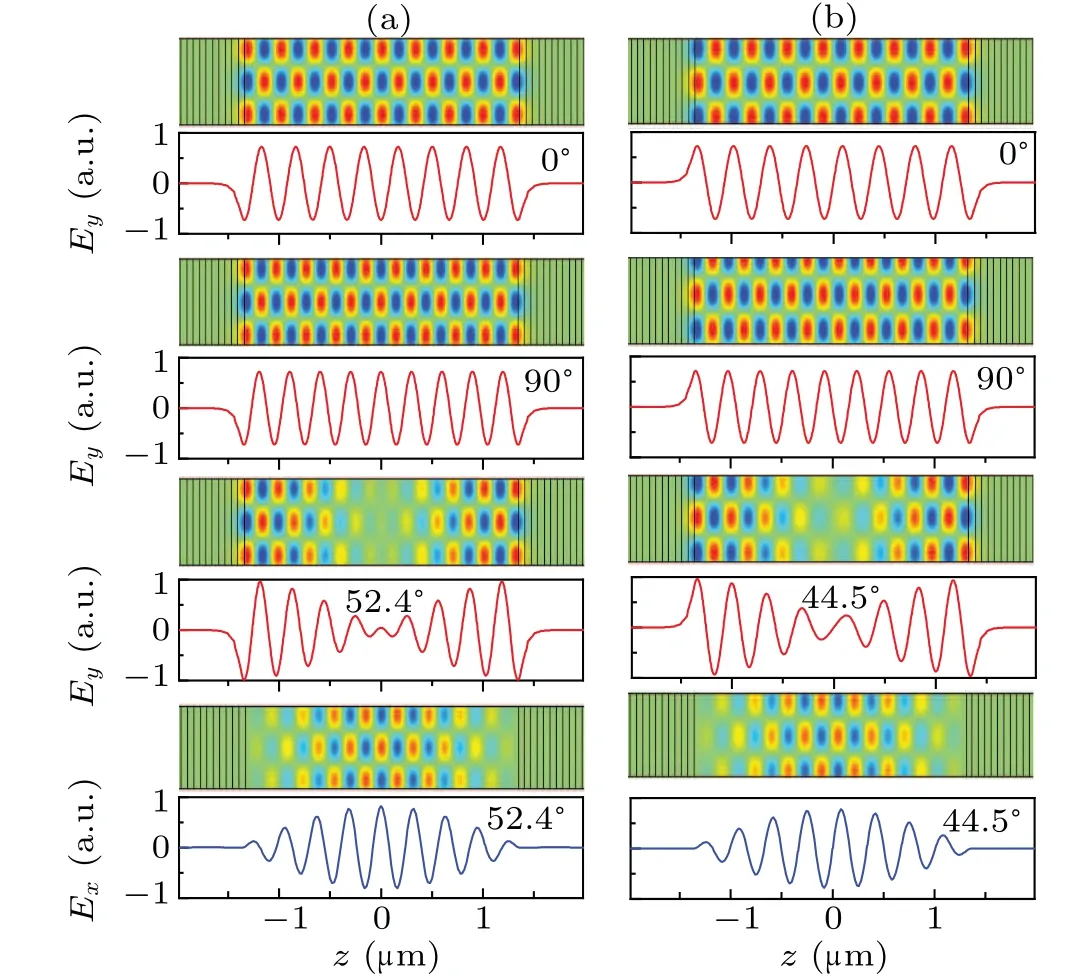
Fig.2. Field distributions of the BICs in the two neighbouring bands. Panels(a)and(b)correspond to the upper and lower bands shown in Fig.1(d)marked with red and blue braces, respectively. The numbers suggest the orientation angle of the optical axis of the BDL. The unit a.u. is short for arbitrary units.
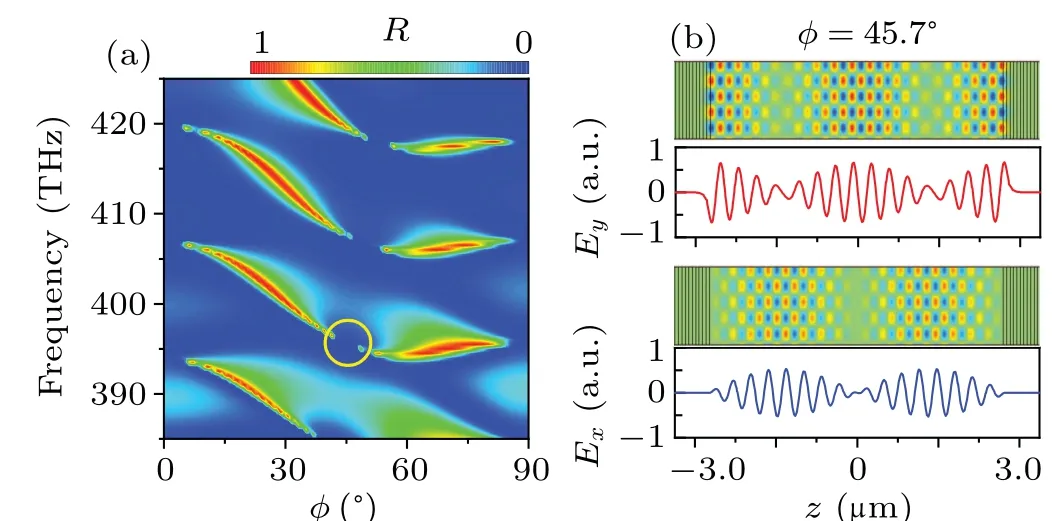
Fig. 3. (a) Reflectance spectra of the TM wave through the system with doubled BDL length. (b) The eigenstate field distributions of the FW-BIC indicated by the circle in panel(a).
The strategy described above provides a method to achieve BICs in 1D MDPhCs. To make it convenient for practical application, a modified scheme is proposed. As shown in Fig.4(a),the MDPhC segment on the right side is replaced by a metal (silver) plate, which serves as a reflection mirror.Meanwhile, the thickness of the BDL is reduced by half to maintain the working wavelength. Here the material loss of the metals is considered. The collision frequencyγis set as 2.871×10¹³rad/s according to reported value of silver.[31]The reflectance of the TM wave by this system is shown in Fig. 4(b). Compared with the spectra of the symmetric system shown in Fig. 1(d), the number of resonant modes is decreased by half. The boundary condition at the metal-BDL interface prohibits the existence of the even modes in the structure and hence only the odd modes survive. For the survived odd modes, the resonance behavior is similar with that in the symmetric structure, with the width of the cavity mode diminishes atφ= 0°, 90°and an angle between them. The Quality factor of a resonance depends on the radiative loss and the non-radiative loss such as material absorption. Here both the totalQfactorQtotand radiativeQfactorQrare calculated. Figure 4(d)showsQtotandQrfor one of the resonant branches, respectively. Due to the metallic loss,Qtotdrops significantly. Nevertheless,the radiative partQrnear the BICs are still extremely high. Thus, for practical application, this scheme still can be used to suppress the radiative loss. The field patterns corresponding to the FW BIC indicated by the circle in Fig. 4(b) are shown in Fig. 4(c), which are highly similar with that of the odd modes shown in Fig. 2 with the mirror surface corresponds to the middle of the BDL in Fig.2.
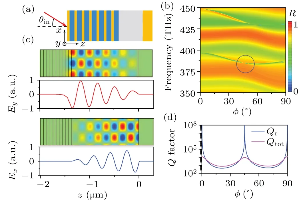
Fig. 4. BICs in the modified system. (a) Structure of the modified system in which the right half of the original system is replaced by a metal mirror.(b) TM reflectance spectra of the system. The circle indicates the location of the FW BIC.(c)The eigenstate field patterns correspond to the FW BIC.(d)The Q factor of the system. Qtot and Qr represent the total and radiative Q factors,respectively.
3. Conclusion
BICs are realized in a 1D photonic system composed of a BDL sandwiched between two MDPhC segments. The MDPhCs provide a TM wave continuum and prohibit the propagation of the TE wave. The BDL,on the other hand,provides another two orthogonal polarization channels and then the polarizations can be mixed.Due to the polarization incompatibility or destructive interference of the TM components of the e wave and o wave,SP BICs and FW BICs are achieved in this system. A modified structure favorable for practical fabrication and application is also proposed. This work may provide instructive guidance to improve theQfactor for related plasmonic systems.
Acknowledgement
Project supported by the National Natural Science Foundation of China(Grant Nos.12074049 and 12147102).
- Chinese Physics B的其它文章
- Formation of high-density cold molecules via electromagnetic trap
- Dynamics of molecular alignment steered by a few-cycle terahertz laser pulse
- Terahertz spectroscopy and lattice vibrational analysis of pararealgar and orpiment
- Molecule opacity study on low-lying states of CS
- Finite-time Mittag–Leffler synchronization of fractional-order complex-valued memristive neural networks with time delay
- Ultrafast Coulomb explosion imaging of molecules and molecular clusters