
Humanoid control of lower limb exoskeleton robot based on human gait data with sliding mode neural network
2022-12-31 03:45JunYuShuaishuaiZhangAihuiWangWeiLiZhengxiangMaXuebinYue
Jun Yu|Shuaishuai Zhang|Aihui Wang|Wei Li|Zhengxiang Ma|Xuebin Yue
1Zhongyuan‐Petersburg Aviation College,Zhongyuan University of Technology,Zhengzhou,China
2School of Electric and Information Engineering,Zhongyuan University of Technology,Zhengzhou,China
3School of Intelligent Engineering,Zhengzhou University of Aeronautics,Zhengzhou,China
4Department of Electronic and Computer Engineering,Ritsumeikan University,Kusatsu,Shiga,Japan
Abstract Lower limb exoskeleton robots offer an effective treatment for patients with lower extremity dysfunction.In order to improve the rehabilitation training effect based on the human motion mechanism,this paper proposes a humanoid sliding mode neural network controller based on the human gait.A humanoid model is constructed based on the human mechanism,and the parameterised gait trajectory is used as target to design the humanoid control system for robots.Considering the imprecision of the robot dynamics model,the neural network is adopted to compensate for the uncertain part of the model and improve the model accuracy.Moreover,the sliding mode control in the system improves the response speed,tracking performance,and stability of the control system.The Lyapunov stability analysis proves the stability of the control system theoretically.Meanwhile,an evaluation method using the similarity function is improved based on joint angle,velocity,and acceleration to evaluate the comfort of humans in rehabilitation training more reasonably.Finally,to verify the effectiveness of the proposed method,simulations are carried out based on experimental data.The results show that the control system could accurately track the target trajectory,of which the robot is highly similar to the human.
1|INTRODUCTION
For various reasons such as ageing,diseases,traffic accidents,etc.,the number of patients is increasing in the world who has lower extremity dysfunction.These patients suffer not only from physical and mental suffering but also from family and social pressure.A large number of studies have shown that the motor nerves of the human body have strong plasticity,and appropriate rehabilitation training will help patients achieve functional rehabilitation of limbs[1,2].If the patient's remaining motor cortex areas are still preserved,their limb motor function has a high probability of recovery after specific exercise training.[2].Many studies have shown that using robots to help patients in rehabilitation training is an effective treatment method[3,4].Therefore,the research of robot control systems is a valuable topic in rehabilitation robots.Many researchers have proposed various control strategies,such as PD control[5],sliding mode control[6],fuzzy control[7],and so on.The sliding mode controller shows efficient performance in controlling the exoskeleton robot to assist in passive rehabilitation training of patients.At the same time,it has strong robustness and excellent tracking performance[8].Meanwhile,in order to achieve the better rehabilitation,a humanoid reference trajectory design is an indispensable section.
Gait planning is the crucial point of controller design.By planning the trajectory of the centre of gravity and the zero motion point,the gait of the humanoid robot can be quickly and smoothly planned[9].Based on the three‐dimensional linear inverted pendulum model and the principle of minimising energy consumption,the gait trajectory parameters of the humanoid robot are optimised[10].The gait of the normal human has great significance to the trajectory planning of rehabilitation robots.The natural human gait not only ensures the safety and comfort of the rehabilitation robot but also corrects the deformed gait of the patient.3‐D motion capture systems are widely used in biological motion capture[11].Ningning and colleagues collected human gait data through a three‐dimensional motion capture system,thereby designing a robust adaptive PD‐like controller[12].Meanwhile,the uncertainty of the robotic system is another key point in the controller design.The radial basis function(RBF)neural network is often used to eliminate the uncertainty of the system and is a widely used function approximation method[13].Qingyun and colleagues proposed adaptive sliding mode neural network control and tested the performance of neural networks approximating non‐linear errors in non‐linear systems[14].In the study of rehabilitation robots with uncertain system dynamics,He Wei used an adaptive neural network to approximate an unknown model of the robot[15].Zhongbo and colleagues proposed a novel RBF neural network‐iterative learning control algorithm and conducted research on lower limb rehabilitation robot‐assisted passive training of patients[16].
This paper proposed a human‐like sliding mode neural network control method based on human gait data.The schematic diagram of the control system is shown in Figure 1.The commercial motion capture system Nokov was used to gather gait data of normal people.The ideal gait joint angle was obtained through clustering and data fitting,which was used as the reference trajectory of lower limb exoskeleton robots(LLERs).That is the ideal trajectory in the figure.The ideal trajectory has great significance for correcting the deformed gait of patients.Considering the dynamics model's inherent uncertainty of LLER,a neural network was used to compensate for the robot's model that cannot be accurately modelled algorithmically.In order to improve the adaptability and stability of the control system,sliding mode control is introduced.However,sliding mode control is prone to chatter near the sliding mode surface.The feedforward control with human gait characteristics is introduced to overcome the shortcomings of sliding mode control.The feedforward control has reasonable compensation for high‐frequency disturbance performance,and the feedforward input that is adapted to the system dynamics can be calculated for any sufficiently smooth ideal trajectory.Therefore,this paper introduced the human gait data and the joint output angles of the robot model into the control system by feedforward control,which improves the control effect of the system.This feedforward controller introduces the joint torque of human motion characteristics for the robot control torque.The robot model is a dynamic equation of motion established based on the link model.Feedforward control was also widely used in other robotic control;Chengyuan designed a control scheme that included an iterative learning control feedforward controller,an inverse dynamics feedforward controller,and a PD feedback controller[17].The accuracy of the robotic arm control has been improved.Madsen and colleagues proposed an adaptive feedforward friction compensator to compensate for the prediction errors of Coulomb friction and viscous friction[18].The results show that the torque prediction error and tracking error of the system is significantly reduced.In this paper,feedforward control calculates joint input using the desired robot motion trajectory and corresponding ground reaction force.Specifically,feedforward control improves the dynamic performance and control accuracy of the control system by predicting the driving force of the robot,that is,the torque required for the robot to drive the human to perform rehabilitation training.On the other hand,the feedforward control also makes the motion trajectory of the robot closer to that of human beings and realises the humanoid motion of the robot.At the theoretical level,based on the Lyapunov stability condition,it is proved that the control system is asymptotically stable.Finally,the simulation results demonstrate the effectiveness and comfort of the trajectory tracking of the control system.
2|HUMAN GAIT DATA COLLECTION
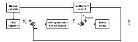
FIGURE 1 The schematic diagram of the control system
Three‐dimensional(3D)motion capture systems have become an essential tool for analysing human motion,and that is widely used in the biomechanical analysis field.Pfister evaluated the availability of the KinectTMwith Brekel Kinect software in comparison to Vicon Nexus during sagittal plane gait kinematics[19].Laribi and Zeghloul used the commercial motion capture system Vicon to analyse the typical walking mode of human beings,which can be used as reference knowledge for the research and development of humanoid robots[20].Mihradi established an optical motion‐capture system for 3‐D gait analysis and verified that this system could be used for kinematics and dynamics analysis of the human gait[21].Especially in the movement of the lower limbs of the human,3‐D motion capture systems can provide sufficient precision and accuracy.During routine gait studies of able‐bodied subjects,Cloete and Scheffer confirmed that inertial motion capture and optical motion capture could provide acceptable accuracy and repeatability,and the joint angles of the knee and hip are very well on the sagittal plane[22].
In this paper,human gait data were gathered by a commercial motion capture system Nokov.This system can satisfy the most demanding requirements of the motion capture industry.As a real‐time application,the results of the motion capture can be viewed instantly while simultaneously saved in several file formats.In addition,this software has a built‐in set of tools to edit and process data in a graphical processing interface,without the need for additional software packages.System setup and calibration are fast and straightforward,with immediate feedback,a high degree of accuracy,and precision.The 3‐D motion capture space based on experimental devices is built(as shown in Figure 2).During data collection,the calibrated system records the positional changes of the identified marker points in 3‐D space with high precision and accuracy,while device B records the ground reaction force data simultaneously.
3|GAIT DATA ANALYSIS
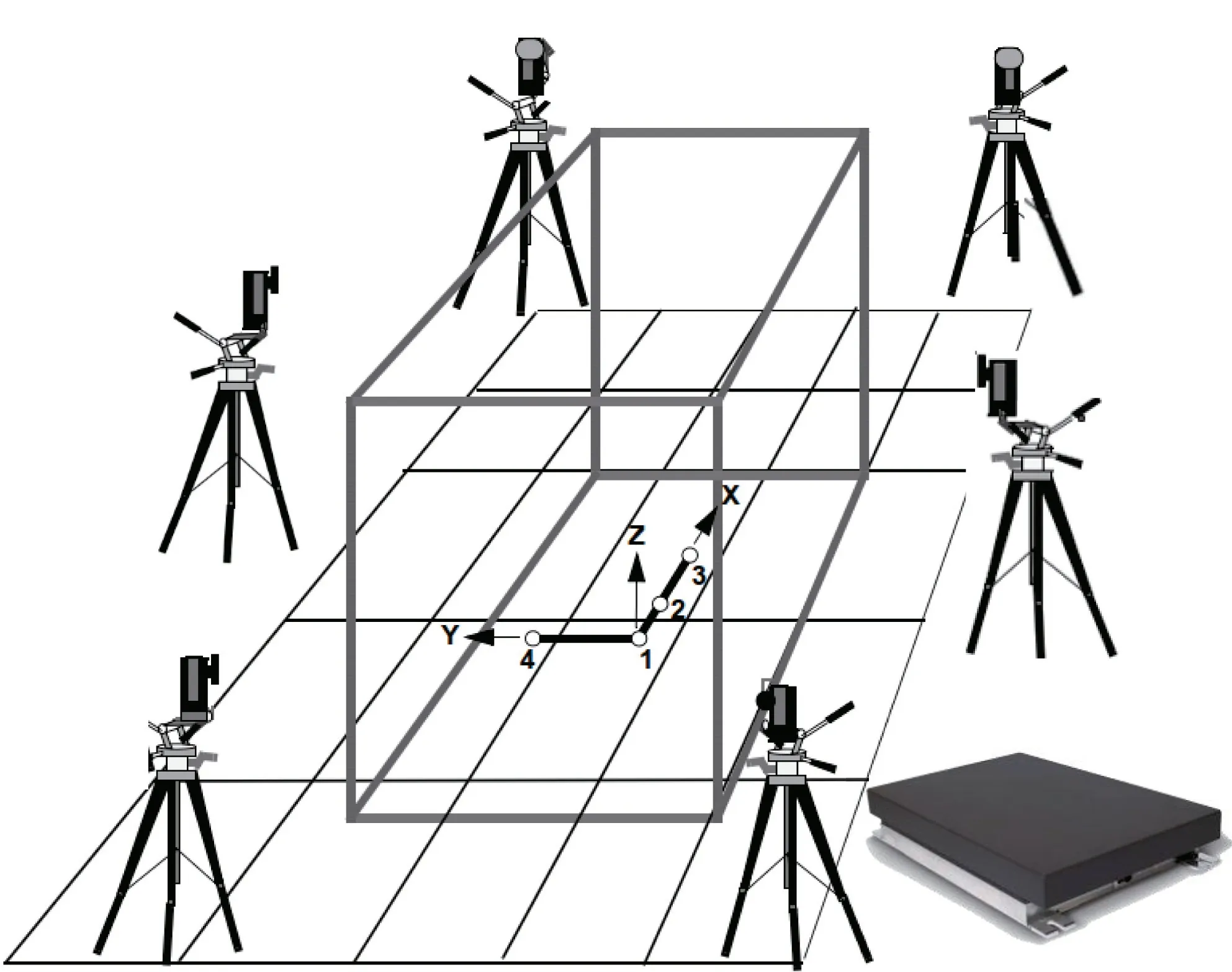
FIGURE 2 Typical configuration of the Nokov motion capture system.A—MARS cameras.B—Force measuring platform.C—Motion capture space
Human gait characteristics are significant for LLER humanoid control.To obtain the human gait data,markers were fixed on the outside of the subject's joints,and the subjects walked in the constructed 3‐D motion capture space.Then,record the coordinate change information of each joint reflection marker point and ground reaction force data.During rehabilitation training,LLER is performed in the sagittal plane.Therefore,we are not interested in the information on they‐axis.Analogously,the relationship between the spatial position coordinates of each joint and the angle of each joint is found in the collected data.In order to make LLER have the characteristics of human motion and simplify the calculation,the human motion model and LLER mechanism are simplified as a two‐link model(as shown in Figure 3).The joint position data of the hip jointa(hip_x,hip_z),the knee jointb(knee_x,knee_z),and the ankle jointc(ankle_x,ankle_z)are used.The joint anglesθ1andθ2can be obtained by the tangent theorem.
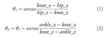
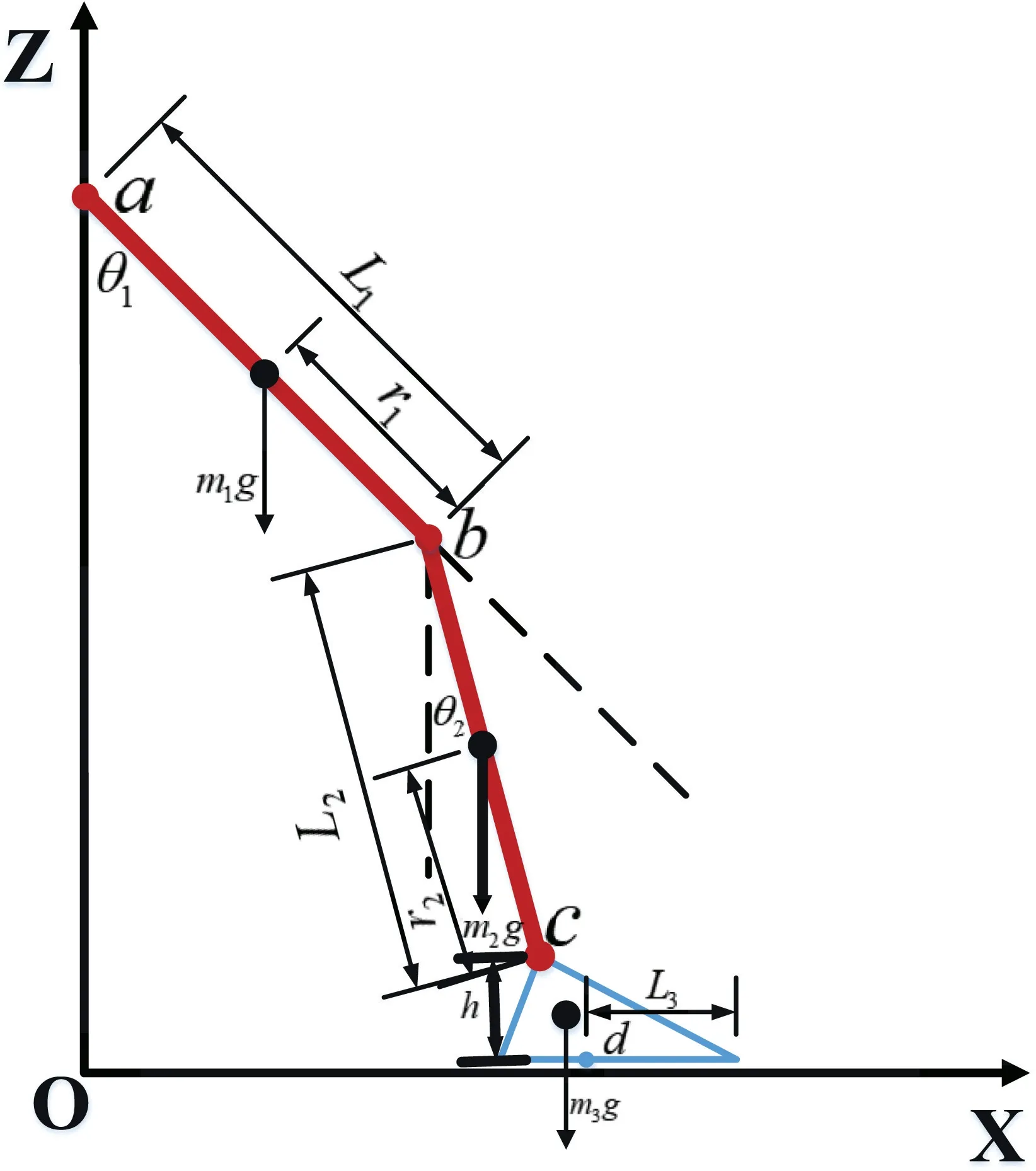
FIGURE 3 Two‐link model.a—Hip joint.b—Knee joint.c—Ankle joint,L1 and L2—the distance between the joints,θ1—angle of hip joint,and θ2—angle of the knee joint
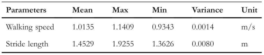
TABLE 1 Characteristics of stride length and a walking speed of volunteers
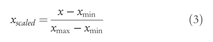
Gait data of a subject(67.5 kg,1.68 m)are captured in the 3‐D motion capture space.Because many rehabilitation robots only move on the sagittal plane,the dimensionality of the gait data is reduced to the sagittal plane.Meanwhile,one cycle of gait data of the volunteers from the entire gait data based on the pressure data of the two force measurement platforms were distinguished.From these gait data,some walking characteristics of the subject were extracted.The gait data characteristics of this volunteer are shown in Table 1.This table shows some basic characteristics of the volunteers'data collected in this study,including walking speed and stride length.The parameters include mean,maximum,minimum and variance.To organise all gait data into the same gait period,we used the Min–Max scaling method to normalise the data(as shown in Figure 4),which is widely used in machine learning(Equation 3).For the convenience of description,this paper uses time as a variable to divide the phase of the gait cycle.The complete gait cycle is partitioned based on the measured values of the plantar feedback force.The cycle starts from the initial landing of the sole of one foot and ends when the sole of the other foot left the ground.
To obtain the gait trajectory that best reflects the characteristics of the lower limbs of the human body,a fuzzy C‐means(FCM)clustering algorithm is adopted to avoid the interference of asynchronous gait data.The FCM clustering algorithm was one of the most popular ongoing research algorithms,and it effectively solved problems in various areas[23].The FCM clustering algorithm was the best clustering method to divide a collection of objects into multiple classes of similar objects,which can effectively partition the data set[24].Many scholars have conducted extensive research on FCM clustering algorithms,such as the weight exponentm[25],the effect of data distributions[26],non‐linear clustering problem[27],and automatic FCM clustering algorithm[28].
Based on the clustered gait trajectory in Figure 4,the desired trajectory fused with human motion feature information was fitted and planned(as shown in Figure 5).Commonly used fitting methods are Fourier,Gaussian,and Polynomial.Comparing the fitting results of different methods(as shown in Table 2),Fourier has the smallest fitting error and the highest accuracy,which is the most suitable.The parameterised expected trajectories(curve 4)and(curve 5)were obtained after Fourier fitting.These gait trajectories reflect the laws of human motion,which can be used as the desired treatment trajectories of LLER rehabilitation training to ensure the safety and comfort of users during the rehabilitation training process.


FIGURE 4 The lower limb joint angle during the human motion.(a)The joint angle data of the hip joint in the same gait period.(b)The joint angle data of the knee joint in the same gait period
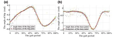
FIGURE 5 After the Fourier fitting gait trajectory.(a)Hip joint motion trajectory after fitting.(b)Knee joint motion trajectory after fitting

where,θd_hipis the desired hip trajectory,andθd_kneeis the desired knee trajectory.The changes in plantar force during human walking were recorded by the three‐dimensional force measurement platform,as shown in the Figure 6.In a gait cycle,the stance phase occupies approximately 60% of the cycle,and the swing phase occupies approximately 40%of the cycle.When the soles of the feet hit the ground,the soles of the human impact the ground,which quickly reduces the speed of the legs to zero.This impact force is a huge instantaneous force for humans,which affects the stability of humans when walking.With the automatic adjustment of the human musculoskeletal system,the impact disappears.When preparing to lift the foot,the sole of the human foot works on the ground to obtain a reaction force to raise the centre of gravity of the body and prepare to move forward.Humans complete the movement process by alternating their legs with each other to achieve normal walking.
The change of plantar force is related to the gait characteristics of the human body,the spatial position of each joint,and the movement state of the musculoskeletal body.At the same time,the human lower extremities drive the joint motion by the torque generated by the musculoskeletal system.Therefore,using the torque generated in the human motion system as the joint driving torque of the robot will further improve the dynamic performance and control accuracy of the control system.Because the robot used in this paper onlymoves in the sagittal plane,we only focus on the components of the plantar force on theXandZaxes.To analyse the changes of the joint moment for lower limbs deeply when the human body moves,this paper solves the moment of the ankle joint,the knee joint,and the hip joint in turn.
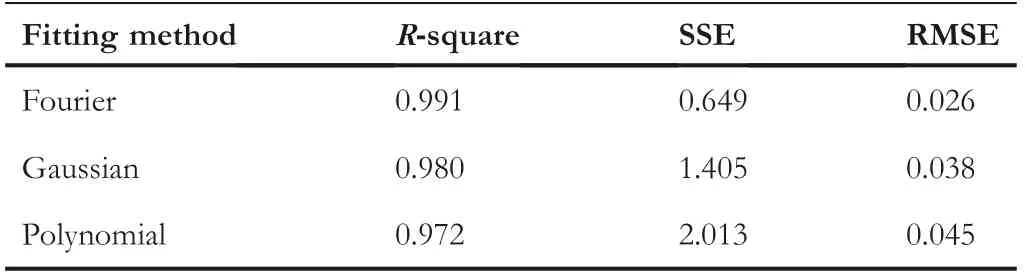
TABLE 2 Comparison table of results for different fitting methods
For the simplicity of the study,this paper makes the following assumptions:
(1)The torso of the human body is in an upright state when walking,
(2)The centroid of each limb segment can be accurately located,and
(3)The weight of each limb adopts the research results of
Rudolfs[29].
As shown in Figure 3,where,m1,m2andm3are the weights of the thigh,calf and foot,respectively.L1,L2andL3are the lengths of the thigh,calf and sole,respectively.a,b,canddare the positions of the contact force points of the hip joint,knee joint,ankle joint,and sole of the foot,respectively.r1andr2are the distance from the centre of mass of the thigh to the knee joint and the distance from the centre of mass of the calf to the knee joint.gis the acceleration due to gravity andhis the distance from the sole of the foot to the ankle joint.
The general form of calculating the torque at a certain point can be expressed as,

where,∑MPis the sum of the moments at pointp,Iis the moment of inertia of the object,rpis the vector from pointPto the centroid,andais the acceleration of the object's centre of mass.
Since the foot was not rotated during walking,the moment sum of the ankle joint is zero at this time,
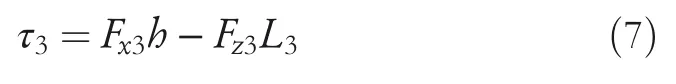
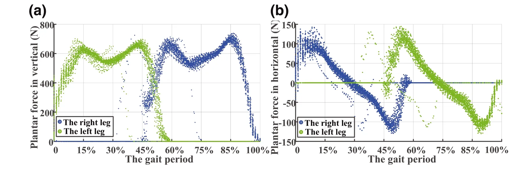
FIGURE 6 The changing trend of plantar force when humans walk.(a)The change trend graph of the plantar force of the human in the vertical direction.(b)The change trend graph of the human plantar force in the horizontal direction
where,Fx3is the component of the plantar force in theX‐axis direction andFz3is the component of the plantar force in theZ‐axis direction.Before solving the momentτ2of the knee joint,the forcesFx2andFz2at the knee must be found first.According to Newton's second theorem,

From the knowledge of robot dynamics,
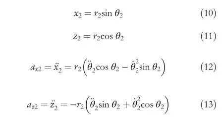
Simultaneous Formulas(8),(12)and(9),(13),get,

Before solving the torque at the hip joint,the forces at the hip joint also must be found.

From Formulas(7),(16),and(23),the moment of knee joint and hip joint can be obtained from the force of the sole(as shown in Figure 7).
After the joint torque calculated above,there were some burrs and fluctuations.When applied to the robot control,in order to avoid the secondary damage of the burr signal to the affected limb,the calculated joint torque was filtered to make the joints'torque smoother.The joints moment after processing were shown in Figure 8.
4|CONTROLLER
Due to the periodicity and symmetry of the LLER motion,this paper studies the motion characteristics of the robot's unilateral legs and simplifies the LLER model into a two‐link model.The dynamics of LLER are described by Ref.[19].
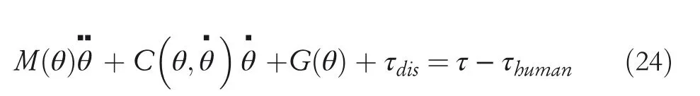
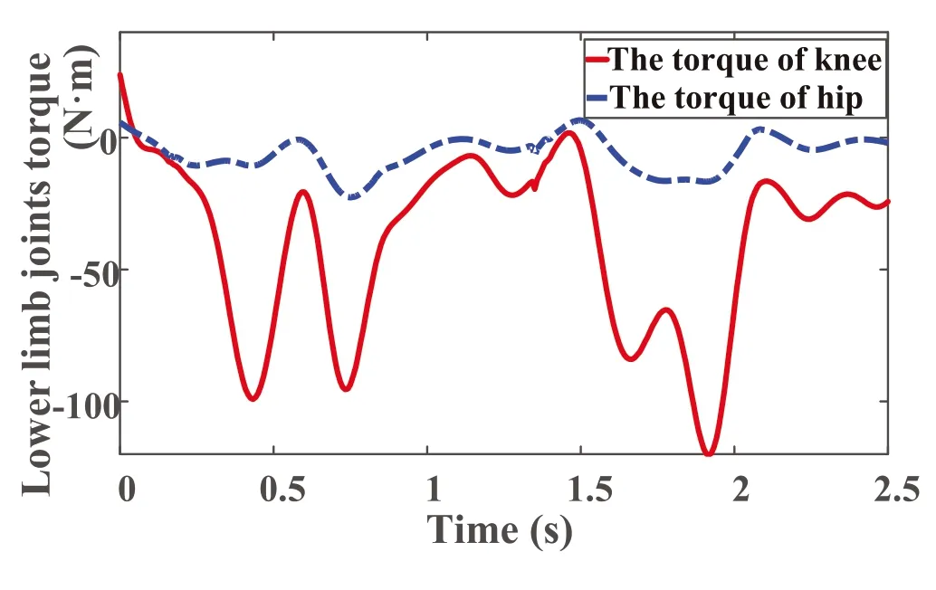
FIGURE 7 The changing trend of plantar force when humans walk.(a)The change trend graph of the plantar force of the human in the vertical direction.(b)The change trend graph of the human plantar force in the horizontal direction

FIGURE 8 The changing trend of plantar force when humans walk.(a)The change trend graph of the plantar force of the human in the vertical direction.(b)The change trend graph of the human plantar force in the horizontal direction
where,M(θ)∈R2×2is a positive definite inertia matrix,is the Coriolis force and centrifugal force matrix,G(θ)∈R2×2is the gravity matrix,τdis∈R2×2is external disturbances,τhuman∈R2×2is a feedforward control output with human body motion mechanism,andis the torque of the hip joint and knee joint,respectively.
The parameters ofM,C,Gmeasured by physical methods were always inaccurate.Therefore,the dynamics function(24)can be rewritten as follows:

M=M0+ΔM,C=C0+ΔCandG=G0+ΔG.Where,M0,C0,G0are known parameter matrixes andΔM,ΔC,ΔGare unknown parameter matrixes.
Rearranging the function(25),the dynamics function can be re‐expressed as

It is complicated to obtain the parameters of thefθ,,due to the uncertainty of the dynamic model of the LLER and the effects of unknown external disturbances.
The RBF neural network selected in this paper is a neural network with a three‐layer structure,named the input layer,the hidden layer,and the output layer(as shown in Figure 9).Used radial basis functions(such as Gaussian functions)as activation functions.Because the parameters of the model can be obtained directly through matrix operations and random sampling,the network structure is simple and the number of layers is small,the training speed is very fast,causing low‐latency and low computation requirements in robot control research.The RBF neural network was used to compensate for the non‐linearity of the controlled object and reduce the approximation error[30,31].Some research has shown that RBF neural network can approximate any non‐linear function[13].Therefore,we use the RBF neural network to approximate the function
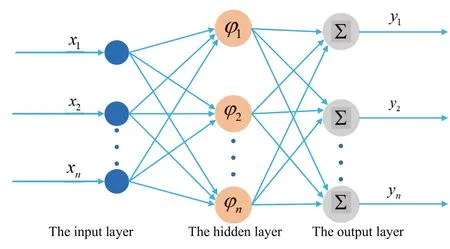
FIGURE 9 Radial basis function neural network structure
The output of the RBF neural network is defined as
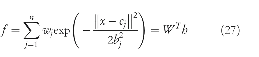
where,xis the input of the neural network,cis the coordinate direction of the Gaussian function centre point,bis the width of the Gaussian function,andwis the weight of the RBF neural network.The approximation error of the RBF neural network is
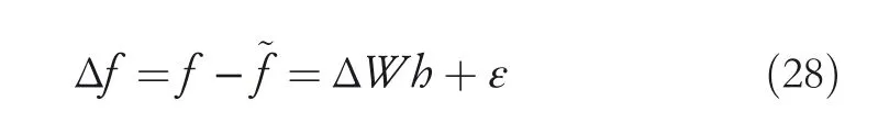
where,ɛis a small positive number,ΔW=W−.ΔW,W,are the error,actual value and estimated value of the neural network weights,respectively.
Before explaining the control strategy,the properties and the assumptions that were used in this paper could be shown as follows:
Property 1.The matrixMqis symmetric and positive definite.
Property 3.There exist positive numberγi,i=1,2,3,4,5.
The‖M0‖≤γ1,‖C0‖≤γ2,‖G0‖≤γ3,‖τdis‖≤γ4,‖τhuman‖≤γ5which means all items are bounded.
Property 4.The functionf(θ,,)is bounded.
5|CONTROL SYSTEM DESIGN
First,assume that the function off(θ,)is known.Define the tracking errore=θd−θ,then get˙e=−,where,θdis the desired gait trajectory,andθis the actual gait trajectory.Introduce a dummy controlφ.Where,λ1is a positive definite matrix.

Define the sliding mode function as

Combining Formulas(29)and(30),˙ecan be obtained,

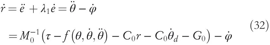
Deriverto get,
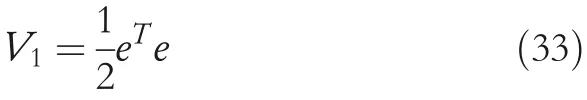
The Lyapunov candidate function 1 is
Its derivative is written as

Because it is impossible to determine whetheris less than or equal to 0,so design the Lyapunov candidate function 2 as

Its derivative is written as
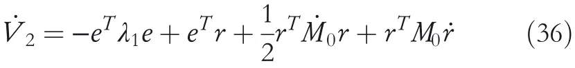
Taking Formula(32)into(36),
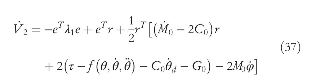
It can be known by property 2 that−2C0is an obliquely symmetric matrix,which can be denied from the definition of an obliquely symmetric matrixthat holds.
Therefore,the designed control law is,

where,λ2is a positive definite matrix.
Combining Equations(37)and(38),

However,the full parameters inare not available.Therefore,control law(38)is not suitable for robotic systems with uncertainty.Therefore,this paper adopts RBF neural network to approximate the uncertainty function
The control law is,

The adaptive law of designing the RBF neural network is,

where,ηis a positive definite matrix.
The Lyapunov candidate function 3 is
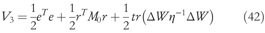
Its derivative is written as

From Equations(35)and(39),it can be known that
Bring Equation(40)into Equation(43)to get,

It can be known that
Only ifr=0,V3≡0 and≡0 has come into existence.According to the principle of LaSalle invariance,the control system is globally asymptotically stable.
6|RESULTS
To verify the effectiveness of the proposed control strategy,a simulation was carried out in Matlab/Simulink and the parameters of the control system were selected.
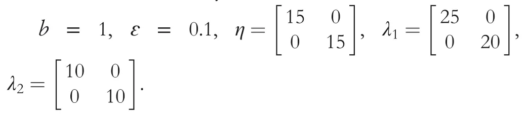
The simulation was carried out using Matlab,and the results are shown in Figure 10.The tracking performance and tracking errors of the hip joint and knee joint angles were given in Figure 10(A1)and(A2).Both the hip and knee joints of the robot successfully tracked the expected trajectories.The tracking errors converge to a very fairly small value which was less than 0.07 rad and continue to connect to the smaller values at a very slow rate.And the convergence rate was very smooth.The joint torque of the hip joint and knee joint ranges from−40 to 40 N m and from−50 to 20 N m in Figure 10(A3)and(A4),respectively.And there were no spikes and jitters in the figure.Furthermore,the joint speed of the hip and knee joints were very similar to the joint speeds of human motion(shown in Figure 10[B1]and[B2]).The performance indexes of the joint angle tracking error were shown in Table 3.MEAN:Measure the result of averaging all values that deviate from the true value.RMSE:Root‐mean‐square error.ISE:Integral square error.ITSE:Integral times square error.IAE:Integral absolute error.The MEAN and RMSE indicators show that the trajectory tracking effect of the hip and knee joints was excellent,and it can quickly track the reference gait trajectory.The ISE,ITSE,and IAE reflected the error of the control strategy in the later stage of the quick response,the damping characteristics and transient response of the control strategy,and the oscillation of the transient response of the control strategy,respectively.The knee joint had a good performance in all performance indicators,and its transient response characteristics,damping characteristics,and tracking performance were all within an excellent level.However,the transient response characteristics and resistance characteristics of the hip shutdown were slightly worse.The specific factor is that the movement of the hip joint in the human body is complicated,but only the motion of the hip joint in the sagittal plane was considered.

TABLE 3 The performance indexes of the joint angle tracking error
FIGURE 1 0 Simulation result graph.(A1)The joint angle tracking of the hip joint.(A2)The joint angle tracking of the knee joint.(A3)The hip joint torque output by the controller.(A4)The knee joint torque output by the controller.(B1)The joint angular velocity tracking of the hip joint.(B2)The joint angular velocity tracking of the knee joint.(B3)The joint angle tracking error of the hip and knee joints
During robot‐assisted human rehabilitation training,if the movement speed and acceleration are too large,it will cause secondary injury to the patient's limbs.In order to ensure the safety of rehabilitation training and ensure the consistency of the motion trajectory between the robot and the human,the rehabilitation training comfort evaluation function designed in this paper is shown in Formula(47).

where,θd,andare the desired joint angle,angular velocity,and angular acceleration,respectively.θ,andare the actual angle,angular velocity,and angular acceleration of the robot joint during training.a,bandcrepresent the weights,which are 0.1,0.3 and 0.6,respectively.Whenfcis close to 1,it shows that the robot's trajectory is highly similar to the trajectory of the humans,which also reflects the comfort level of humans when using the robot.These results are shown in Figure 11.The average values and RMSE of the comfort function of the hip and knee joints are 0.9457,0.8597,0.0032,0.0491,respectively.Therefore,the motion trajectory of the robot was similar to the motion trajectory of the human,which also means that the robot had the motion characteristics of the human.Because the structure of the robot and the human were fundamentally different,these similarities were maintained within a specific range.In this paper,the proposed controller is used to introduce the gait data features from the real human body into the simulation control system of the lower extremity exoskeleton robot.The joint torque of the robot is compensated.The compensation combines the human gait characteristics with the control of the lower extremity exoskeleton robot and enhances the flexibility and anthropomorphism of the lower extremity exoskeleton robot.It provides a new way of thinking for the anthropomorphic control of robots.
7|DISCUSSION
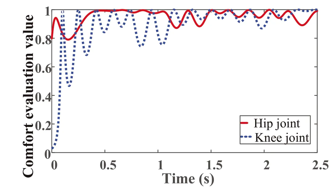
FIGURE 1 1 Evaluation results of the comfort function
With the development of society,robots will receive more and more attention from researchers,especially rehabilitation robots.How to make robots move like humans is a hot topic.The design of the controller is the key to realising human‐like motion in robots,and many researchers have made major breakthroughs in this field.In this paper,a novel controller was designed based on the natural motion gait data of healthy people,which achieved the goal that the motion characteristics of the robot were similar to those humans during the rehabilitation training process.Firstly,a 3D motion capture system was established to collect normal human gait data.Then,according to the motion characteristics of human lower limbs,a feedforward controller was designed to make the control system have specific humanoid features.In addition,in order to reduce the modelling error caused by the difference in human‐machine structure,a sliding mode controller based on the RBF neural network was proposed.The stability of the proposed control system was also demonstrated,theoretically.The effectiveness of the control strategy was verified by Matlab/Simulink simulation.Simulation results showed excellent trajectory tracking performance and high comfort,and also demonstrated that the trajectory of the robot was similar to the human gait trajectory.The control strategy not only ensured the safety and comfort of the robot but also had a good effect on correcting the deformed gait of patients.At the same time,the control strategy also ensured the efficiency and comfort of rehabilitation training.However,there are still some flaws of this paper that need to be improved.For example,the human motion intention should be incorporated into the robot motion control,so as to realise the real‐time feedback of the user intent of the robot control system.
ACKNOWLEDGEMENTS
The authors would like to thank the Henan Province Science and Technology R and D projects,Young Backbone Teachers in Henan Province,and National Natural Science Foundation for their support of this work.Meanwhile,we also sincerely thank the volunteers for their help in this paper.This research was funded by the National Natural Science Foundation(No.62073297,No.U1813201)and Henan science and technology research project(No.222102520024,No.222102210019,No.222102210016).
CONFLICT OF INTEREST
The authors declare that the research was conducted in the absence of any commercial or financial relationships that could be construed as a potential conflict of interest.
DATA AVAILABILITY STATEMENT
There is no shared data for this paper.
ORCID
Aihui Wanghttps://orcid.org/0000-0002-7531-6240
 CAAI Transactions on Intelligence Technology2022年4期
- CAAI Transactions on Intelligence Technology的其它文章
- Modelling of a shape memory alloy actuator for feedforward hysteresis compensator considering load fluctuation
- Apple grading method based on neural network with ordered partitions and evidential ensemble learning
- An improved bearing fault detection strategy based on artificial bee colony algorithm
- Parameter optimization of control system design for uncertain wireless power transfer systems using modified genetic algorithm
- Passive robust control for uncertain Hamiltonian systems by using operator theory
- Research on trend prediction of component stock in fuzzy time series based on deep forest