
Investigation of Flow Resistance in a U-Shaped Channels at Rotating Conditions Based on Similarity Theory*
2023-11-30 01:53RuquanYouCairuiLiHaiwangLi
风机技术 2023年5期
Ru-quan You Cai-rui Li Hai-wang Li
(Beihang University,National Key Laboratory of Science&Technology Aero-engine Aero-thermodynamics)
Abstract:In this paper,the numerical simulation method is used to study the flow resistance law of u-shaped channels under rotating conditions based on similarity theory.The study compares three geometric models:real model,completely similar model and incompletely similar model for cooling typical U-shaped channels inside turbine rotating blades.The completely similar model is geometrically 4.8 times magnification of the real model,and the rotation radius ratio of the real model is 5.4 times that of the incomplete similar model.It is found that the friction factor of the completely similar model increases with the rotation number,and the difference varies from 6%to 38%.The friction factor of the model after incomplete similarity amplification decreases with the increase of rotation number,and the difference varies from-2% to-30%.The friction factor of the laboratory imperfectly similar amplification model combined the effects of the above two laws,and the predicted difference was within 12%.This study provides a theoretical basisfor subsequent experimentsrelatedtoflowresistance.
Keywords:Flow Resistance;RotatingChannel;SimilarityTheory;Scaled-upChannel
0 Nomenclature
Aarea(m2)
Buo rotational buoyancy parameter,(ΔT/T)Ro2(R/D)
Cpspecific heat at constant pressure(kJ/(kg·K))
Dhydraulic diameter(m)
e/Drib height ratio
hheat transfer coefficient(W/(m2·K))
Kfanning friction factor,ΔPfriction/(4L/D)(1/2ρV2)
Kppressure term for fanning friction factor,ΔP/(4L/D)(1/2ρV2)
Kccentrifugal force term for fanning friction factor,ρω2rdr/(4L/D)(1/2ρV2)
P/erib spacing
Rmean rotating radius(m)
R/Drotational radius ratio
ReReynolds number,ρVinD/μ
Rorotation number,ΩD/V
Ttemperature(K)
TRwall-to-bulk temperature ratio,Tw/Tb
Vmean average velocity(m/s)
Xcoordinate direction(m)
ΔT/Twall temperature ratio,(Tw-Tin)/Tw
Ωrotating speed(r/min)
ρdensity(kg/m3)
μmolecular dynamic viscosity(kg/(m·s))
kheat conductivity coefficient(W/(m·K))
Subscripts
bbulk
fflow
in inlet for heated channel
out outlet
wwall
1 Introduction
Aero-engine turbine blades work in a high temperature environment.In order to ensure the normal operation of turbine blades under high temperature,researchers have studied the cooling technology of turbine blade coolant channel [1-5].Among them,the blade cooling technology of U-shaped coolant channel has better cooling effect and has been widely studied[6-7].
The real model of turbine blade U-shaped channel has the characteristics of large rotating speed,large rotation radius,small hydraulic diameter of the channel,high temperature and large outlet pressure.Since it is difficult for the laboratory to meet the above conditions,the model selected by the laboratory is the enlarged U-shaped structure modeled according to the similarity theory.Due to the limitation of the rotation radius of the experimental platform,the rotation radius of the experimental model is smaller than that of the real model,and the smaller rotation radius leads to incomplete similarity.Whether the friction factor obtained in the laboratory model can be directly used in the actual turbine blade design process needs to be verified.Therefore,the effect of incomplete similarity on the friction factor is numerically studied by rotating a ribbed U-shaped channel.
In the 1970s,J.C.Han et al.began to study the flow resistance and heat transfer characteristics of ribbed internal coolant channels,and studied the effects of rib geometry,rib spacing and rib height ratio on the enhanced heat transfer and flow resistance characteristics of the channel,and obtained the correlation formula between the flow friction factor and Stanton coefficient,rib geometry,rib spacing and rib height ratiop/e[8].It was also concluded that with the increase of the channel blocking ratioe/De,the enhanced heat transfer effect of the channel increases,and the flow resistance also increases[9-10].
Wang et al.[11] simulated a smooth U-shaped internal cooling channel and analyzed the secondary flow structure causing local losses in the channel.Geng et al.[12]optimized the flow characteristics of the U-shaped channel of the turbine blades,and verified the optimized performance of the channel through large eddy simulation.The results showed that the asymmetric turning section and the baffle raised structure significantly weaken the strength of the secondary flow,the downstream flow becomes more uniform,and the pressure loss of the optimized structure is reduced by 38.76%.Zhang et al.[13]used numerical simulation to study the flow heat transfer characteristics and mechanism of the cooling channel inside the cross-ribbed turbine blade.It was found that with the increase of the rib angle and width,the heat transfer capacity of the channel increase and the resistance loss increase.With the increase of the distance between ribs,the heat transfer capacity of the channel decreases and the resistance loss decreases.Ding et al.[14]conducted experimental research on heat transfer and flow resistance of coolant channels in trailing edges of turbine blades with staggered ribs.The experimental results showed that the heat transfer effect and flow resistance of the ribbed channel with variable section are higher than those of the ribbed channel with equal section,and the comprehensive heat transfer effect of the ribbed channel with variable section is also better than that of the ribbed channel with equal section.Deng et al.[15]carried out the heat transfer and flow resistance measurement experiments on the slotted cross-ribbed channel.It was concluded that compared with the non-slotted crossribbed channel of the same size,the heat transfer effect of the slotted cross-ribbed channel with a certain slot width is significantly improved,while the flow friction factor was decreased accordingly,so the overall heat transfer effect was better than that of the non-slotted channel.
As mentioned above,great progress has been made in testing and studying the flow resistance of coolant channels in turbine blades.Scholars mainly study the resistance characteristics and heat transfer characteristics of different inner coolant channel structures.By optimizing the structure of inner channel,the friction factor can be reduced and the heat transfer effect can be better.However,compared with the scale of coolant channels inside real turbine blades[16],many experimental studies were conducted under conditions which are incomplete similarity.The difference between the friction factor of the real turbine blade model and that of the incompletely similar model used under laboratory conditions needs to be explored.In this paper,for the typical U-channel structure in the rotating turbine blade,the friction factor distribution in the U-channel of the real size model,the enlarged model after complete similarity modeling according to the similarity theory,and the laboratory enlarged size model with incomplete similarity are compared.
2 Problem Description and Numerical Method
2.1 Problem Description
Usually in experimental research,it is impossible to use the real model for experiments,but a similar theory is applied to scale up the actual cooling channel inside the blade to an experimental-scale model.If the magnification is completely similar,according to the geometric similarity,the radius of rotation needs to be magnified by a corresponding multiple.However,the radius of rotation after magnification is too large to be realized in laboratory conditions.The laboratory model has a much smaller rotation radius,which leads to an incomplete similarity between the laboratory model and the real model,which requires the application of similarity theory.The schematic diagrams of the four models are shown in Fig.1.Model 1 is a simplified model based on the inner cooling channel of the real turbine blade.Model 2 is a model that is completely similar to model 1.It has the same rotation radius ratio,wall temperature and outlet pressure as model 1.The rotational radius ratio of model 2 is 5.4 times that of model 3.Model 4 is the model selected for experiments in the laboratory.It has a small rotation radius ratio,low wall temperature,and low outlet pressure.The specific parameters are shown in Tab.1.

Tab.1 Parameters of the model

Fig.1 Schematic diagram of the rotating model
The non-dimensional groups are:
Apply four important dimensionless parameters (Re,Ro,Buo,K)to correlate the flow resistance in the rotary heating channel.It is noticed that the radius of rotation ratio (R/D) is only included in the buoyancy number.The buoyancy number of the experimental models (models 3,4) is smaller than those of the real turbine blade model (model 1) and the buoyancy number of the completely similar model (model 2),resulting in incomplete similarity.The Fanning friction factor is generally used as an important dimensionless parameter to measure the flow resistance characteristics of the channel.As shown in Equ.(1),in the numerical calculation,this paper directly uses the integral method to deal with the ΔPfrictionterm,and the obtained fanning friction factor is more accurate.The fanning friction factor is equal to the sum of the dimensionless pressure term and the dimensionless centrifugal force term,as shown in Equ.(2).The formulas of the dimensionless pressure term and the dimensionless centrifugal force term are respectively shown in Equ.(3)and Equ.(4).
2.2 Numerical Model
Two physical models with different sizes are established,representing the real model and the experimental model respectively.
The numerical model is shown in Fig.2.It is a square section U-shaped rotating channel.TheXaxis is the rotation axis,theYaxis is the cooling air inflow direction,and theZaxis is perpendicular to the rotation axis.The channel cross section of the real turbine blade model is 5mm×5mm,and the experimental model is 24mm×24mm.The hydraulic diameter of the real turbine blade model is 5 mm,and the channel cross section of the experimental model is 24 mm.The inlet and outlet sections are non-heating sections with a length of 10D,a heating section with a length of 10D,the rib height ratioe/Dis constant at 0.1,and the rib spacing ratioP/eis constant at 10.The rotation radius (R) is defined as the length from the coordinate zero point to the midpoint of the heating segment.

Fig.2 Sketch of the physical structure and the calculation model
In this paper,a commercial CFD solver is used to complete the simulation,and the calculation grid uses the structured grid generated by ICEM.In order to ensure the calculation accuracy,according to the requirements of the turbulence model,the cooling channel wall boundary layery+<1 is adjusted by calculation,the height of the first mesh layer on the inner wall of the fluid domain is 0.0015mm,the growth rate to 1.2,the grid quality>0.9,and the total number of grids to be 6.68 million.Grid independence verification was done by adjusting the first grid and grid ratio,as shown in Fig.3.
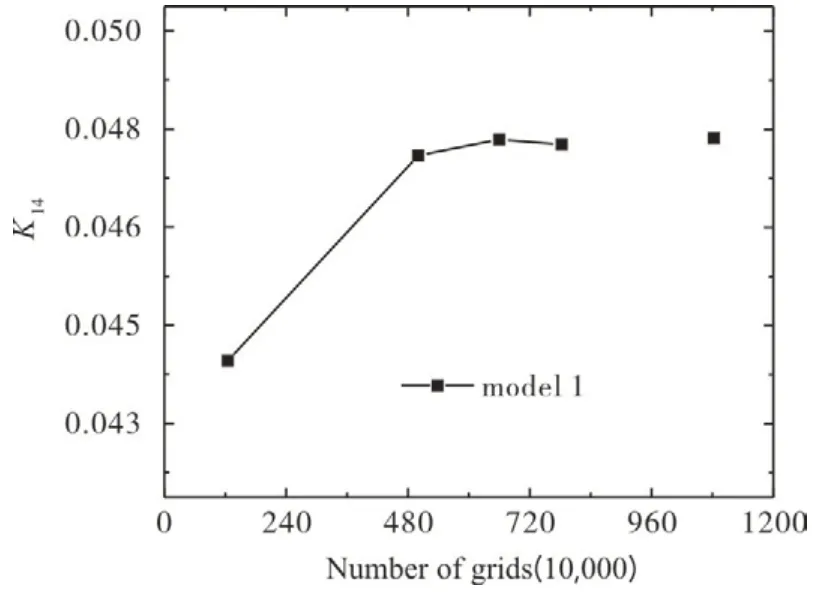
Fig.3 Variation of friction factor K14 with the number of grids(10,000)
In order to ensure the accuracy of simulation,the appropriate turbulence model is particularly important.Firstly,the physical model of U-shaped channel is established,which is the same as that in Tao [17] experiment.Then,the conformance between K-Epsilon,SST,K-omega and LES model is compared.The SST model has the best fitting degree with LES model,and the SST model is adopted in the turbulence model in this paper.
In order to verify the feasibility of the calculation method adopted in this paper,the numerical simulation results are compared with the experimental results of Tao [17] with the same model conditions.The comparison between the experimentally measured friction factor of Tao and the friction factor obtained by numerical simulation when the Reynolds number is 20000 and the rotation number are 0,0.2,0.4,0.6 and 0.8 is shown in Fig.4.The results show that the numerical simulation results and the Tao experimental results are basically the same as the channel flow resistance characteristics with the rotation number,and the values are very consistent.The friction factor obtained by the numerical simulation in the current model is in good agreement with Tao's friction factor results.The maximum average friction factor difference not exceed 28%.

Fig.4 Numerical simulation and verification of Tao[17]experimental results
3 Results and Discussion
3.1 Complete Similarity Verification
Model 1 is a simplified model based on the real coolant channels inside turbine blades,and model 2 is a completely similar model with 4.8 times magnification.The two models have the same dimensionless parameters,including Reynolds number,rotation number and buoyancy number.Therefore,the resistance distribution in the straight channel along the two models should be in good agreement on the same curve.Fig.5 (a) shows the variation of friction factor along the path when the Reynolds number is 40000 and the rotation number is 0.2.It can be seen that the friction factor of model 1 is larger than that of model 2 before and after the turning section,and the friction factor of other regions is well fitted.
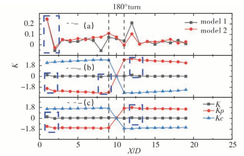
Fig.5 (a)Variation of friction factor along the path between model 1 and model 2 when Ro=0.2(b)Variation of dimensionless parameters along the path of model 1(c)variation of dimensionless parameters along the path of model 2
It can be seen that the friction factor near the first rib(x/d=1) in the entrance section is significantly greater than the friction factor of other parts of the entrance section.The centrifugal force term in Fig.5 (b) and (c) increases with the increase of radius and is positively correlated.Because the pressure drop inX/D=1 is significantly less than the pressure drop in other parts of the entrance section,which leads to the entry effect.The flow inlet section of the fluid is a layer of flow.When the fluid encounters the first rib,a smaller step disturbance is generated.The latter disturbance is the disturbance of coupling and superposition with the previous disturbance,so the entry effect is generated.
The friction factor changes of model 1 and model 2 under different rotation numbers are shown in Fig.6.On the whole,as the number of rotations increases,the difference in friction factor increases.The friction factor of the real model is smaller than that of the completely similar model,and the difference increases from 6%to 38%with the increase of the number of rotations.
Since model 1 and model 2 are completely similar models,the change of physical properties leads to the difference of flow between the two models.Since the model has a smaller velocity of 5m/s and a higher wall temperature of 900K,the difference of the friction factor may be caused by different temperature changes.Fig.7 is the average temperature change diagram of model 1 and model 2 at different rotation numbers at the inlet sectionX/D=5.It can be seen that with the increase of rotation number,the temperature difference between model 1 and model 2 gradually increases.The viscosity of ideal gas is positively correlated with temperature.According to the Reynolds number formula,the greater the viscous force,the smaller the Reynolds number,the smaller the Reynolds number,the smaller the disturbance of the fluid flowing through the rib,the smaller the momentum loss,and the smaller the friction factor,so it appears that the friction factor of the completely similar model in Fig.6 increases with the number of rotations,with a difference from 6%to 38%.
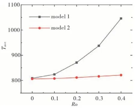
Fig.7 The average temperature of model 1 and model 2 at different rotation numbers at the inlet section X/D=5
3.2 Incomplete Similarity Verification
3.2.1 Effect of rotation radius on friction factor
Model 2 is a completely similar model with a magnification of 4.8 times of model 1,withR/D=107.44.Model 3R/D=20,and other conditions are consistent with model 2.As the larger the radius of gyrate,the larger the centrifugal force,the pressure term and centrifugal force term of Model 3 in Fig.8 (b) and (c) are larger than those of model 2 by an order of magnitude.The friction factor of model 2 at the turning section is larger than that of model 3 at the turning section.

Fig.8 (a)Variation of friction factor along the path between model 2 and model 3 when Ro=0.2(b)Variation of dimensionless parameters along the path of model 2(c)variation of dimensionless parameters along the path of model 3
The variation of the friction factor of model 2 and model 3 at different rotations is shown in Fig.9.On the whole,the difference of the friction factor increases with the increase of the rotation number.The friction factor of the real rotation radius model is larger than that of the laboratory rotation radius model,and the difference varies from-2% to-30%with the increase of the rotation number.

Fig.9 Variation of friction factor of model 2 and model 3 under different rotation number
Fig.10 is the streamline diagram of model 2 and model 3 at different rotation numbers at the inlet sectionX/D=5.The abscissa direction is theXaxis direction of the U-shaped tube,and the ordinate direction is theZaxis of the U-shaped tube.The left side is the outer side,the right side is the inner side.It can be seen that in the static state,the inlet flow in the U-shaped pipe is symmetrically distributed.It can be seen from the streamline diagram that there is no eddy current,and is affected by the wall boundary layer.The flow in the U-shaped pipe is from the corner to the center of the wall,the tendency to converge from the wall to the center of the runner.With the increase of the rotation number,model 2 is more susceptible to the influence of the turning segment.After the rotation number is greater than 0.3,the streamline is no longer symmetric about the z-axis due to the influence of the turning segment.
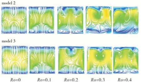
Fig.10 Streamline diagrams of model 2 and model 3 at different rotation numbers at the inlet section X/D=5
It can be seen from Fig.11 that with the increase of the rotation radius,the friction factor of the model is also increasing.The entrance section is not affected by the turning section,and the friction factorK12increases with the increase of the turning radius.The change of the friction factorK23at the turning section is more complicated,and the exit section is greatly affected by the turning section.The friction factor also shows a fluctuating trend with the increase of the rotation radius,but it is relatively flat.The overall friction factorK14of the U-shaped ribbed channel increases with the increase of the radius of rotation.Since the buoyancy number formula includes the rotation radius ratioR/D,the larger the rotation radius ratio,the larger the buoyancy number,the buoyancy number of model 2 is greater than that of model 3,and the buoyancy number is equal to the buoyancy force divided by the inertial force (Coriolis force and centrifugal force).The Coriolis force remains unchanged and the buoyancy number increases,indicating that the change in buoyancy force is greater than the change in centrifugal force.When the buoyancy force is greater than the centrifugal force,the fluid near the surface with a relatively low channel velocity is continuously decelerated under the action of the buoyancy lift force,and separation occurs when the velocity is 0,resulting in a diversion.The generation of backflow causes the absolute value of the pressure drop to decrease,and the friction factor obtained by the fanning resistance formula increases.The buoyancy number of model 2 is greater than that of model 3,which makes model 2 more prone to backflow,resulting in a larger friction factor.

Fig.11 When Ro=0.2,Re=40000,the friction factor changes along the path under different rotation radii
3.2.2 Effects of physical properties on friction factors
Model 4 is a U-shaped channel model adopted in the laboratory,with small rotation radius,low outlet pressure and low wall temperature.Model 3 has high outlet pressure and high wall temperature,and other conditions are the same as model 4.By comparing model 3 with model 4,the influence of wall temperature and outlet pressure on the friction factor is analyzed.It can be seen from Fig.11(b) and (c) that the friction factors of model 3 and 4 are consistent along the path,and it can be seen from Fig.12(a)that the two curves fit well.

Fig.12 (a)Variation of friction factor along the path between model 3 and model 4 when Ro=0.2(b)Variation of dimensionless parameters along the path of model 3(c)variation of dimensionless parameters along the path of model 4
The variation of friction factor under different rotation numbers of model 3 and model 4 is shown in Fig.13.On the whole,the difference of friction factor between model 3 and model 4 irrelevant the rotation number,and the difference between them is less than 13%.
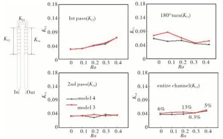
Fig.13 Variation of friction factor of model 3 and model 4 under different rotation number
3.3 Real Models to Lab Models
Model 1 is the U-channel model extracted from the real blades of the engine,and model 4 is the laboratory model.By comparing the two,we can see the difference between the friction factor measured in the laboratory and the friction factor measured by the real engine.The specific data of the two model are shown in Tab.2.It can be seen from Fig.13(a)that the friction coefficients of model 1 and model 4 are poorly fitted in the turning section,and the rest areas are well fitted.Since the rotation radius of model 4 is smaller than that of model 1,the pressure term and centrifugal force term of model 4 are an order of magnitude smaller than those of model 1,as shown in Fig.14(b)(c).

Tab.2 Parameters of model 1 and model 4

Fig.14 (a)Variation of friction factor along the path between model 1 and model 4 when Ro=0.2(b)Variation of dimensionless parameters along the path of model 1(c)variation of di-mensionless parameters along the path of model 4
Fig.15 shows the variation of the friction factor of model 1 and model 4 at different rotation numbers.It can be seen from the figure that the friction factor of the real blade model fits well with the laboratory model overall.When the rotation number is less than 0.4,The difference is less than 12%.From the analysis of 3.1 and 3.2,it can be concluded that the overall friction factor error gradually increases with the increase of the rotation number from the comparison between model 1 (real blade model) and model 2 (completely similar model),and the friction factor of the real blade model is less than the completely similar model.The friction factor of the model is 6%at rest,20%at 0.2 rotation,and 38%at 0.4 rotation.From the analysis of 3.3,it can be concluded that the difference of the overall friction factor between model 2 (real rotation radius model)and model 3(laboratory rotation radius model) gradually increases with the number of rotations,and the friction factor of the real blade model is greater than the completely similar model.The friction factor of the model is-3%at rest,-19%at 0.2 rotation,and-30%at 0.4 rotation.From the analysis in 3.4,it can be concluded that the influence of physical property changes on the change of friction factor has nothing to do with the number of rotations,the real model is smaller than the laboratory physical property model,and the difference of the overall friction factor does not exceed 13%.In summary,the difference of friction factor increases with the rotation number due to the complete similarity change.The friction factor of the real blade model is smaller than the friction factor of the complete similarity model,and the incomplete similarity model(the rotation radius is reduced)leads to the difference of friction factor.As the rotation number increases gradually,the friction factor of the real blade model is larger than that of the completely similar model,and the two offset part of the difference.Finally,the difference of the friction factor between the real blade model and the laboratory model is less than 12%.Since the change of physical properties does not change with the number of rotations,the difference of friction factor between the real model is not directly related to the change of the number of rotations.

Fig.15 Variation of friction factor of model 1 and model 4 under different rotation number
4 Conclusions
In this paper,the difference of friction factor between the real size U-channel model of turbine blade and the laboratory U-channel model with incomplete similar amplification is studied by numerical simulation.Due to the insufficient radius of rotation in the experimental channel,the model with incomplete similar amplification (model 4) cannot obtain the same friction factor as the real model.Therefore,the effects of complete similarity change,rotation radius change and physical property change on friction factor is studied.Through simulation,the following conclusions can be drawn:
1)On the whole,the friction factor of the real model and the laboratory model fit well,and the difference is less than 12%;
2)The friction factor of the fully similar enlarged model increases with the number of rotations,with a difference from 6%to 38%;
3)For the whole channel,the friction factor of the model is positively correlated with the rotation radius;
4)Due to the difference in physical properties (wall temperature,outlet pressure),the difference of the friction factor has nothing to do with the rotation speed,and the difference between the two is less than 13%.
