
Reliability analysis for vertical integration of protection,measurement,merge unit,and intelligent terminal device
2023-12-28 03:31YingLiWeiquanWangLiangZhangZhujianLiangZhenliXuYuanshengLiang
Global Energy Interconnection 2023年6期
Ying Li ,Weiquan Wang ,Liang Zhang ,Zhujian Liang ,Zhenli Xu ,Yuansheng Liang
1.Zhaoqing Power Supply Bureau of Guangdong Grid Co.Ltd.,Zhaoqing,526000,P.R.China
2.School of Electric Power Engineering,South China University of Technology,Guangzhou 510640,P.R.China
Abstract: The reliability analysis of vertically integrated protection devices is crucial for designing International Electrotechnical Commission (IEC)61850-based substations.This paper presents the hardware architecture of a four-inone vertically integrated device and the information transmission path of each function based on the functional information transmission chain of protection devices,measurement and control devices,merging units,and intelligent terminals.Additionally,a reliability analysis model of the protection device and its protection system is constructed using the fault tree analysis method while considering the characteristics of each module of the vertically integrated device.The stability probability of the protection system in each state is analyzed by combining the state-transfer equations of line and busbar protection with a Markov chain.Finally,the failure rate and availability of the protection device and its protection system are calculated under different ambient temperatures using a 110 kV intelligent substation as an example.The sensitivity of each device module is analyzed.
Keywords: Vertical integration of secondary system device;Reliability of secondary system;IEC 61850-based substation;Relay protection
0 Introduction
The increasing density of urban buildings has resulted in stringent space constraints in the design and construction of urban substations.Consequently,higher standards have been imposed for the design,development,and assembly of secondary equipment.The secondary equipment of an IEC 61850-based substation comprises four components:protective intelligent electronic devices (PIEDs),measurement and control intelligent electronic devices (MCIEDs),merging units (MUs),and intelligent terminals (ITs).Device screen cabinets require a large space.However,the use of a four-in-one device,which vertically integrates PIEDs,MCIEDs,MUs,and ITs,allows for a vertically integrated design that reduces the space demand of the secondary equipment [1-4].Four-in-one devices that vertically integrate PIEDs,MCIEDs,MUs,and ITs (PMMI)can be logically and fictitiously connected to crossbay protection devices,e.g.,for station domain and busbar protection,through the process network.This connection enables seamless integration and communication between devices,thus enhancing the overall system performance and reliability.The protection system must ensure the real-time and reliable transmission of sampling data and protection action instructions while ensuring the intended functioning of each module’s hardware and software.The PMMI device and its secondary system cannot be assembled or added together.The reliability analysis model for a PMMI device is more complex than that for discrete devices.Therefore,investigating the reliability analysis model of a PMMI device and its secondary system is essential in the secondary design of a substation.
In the field of system reliability analysis,constructing a reliability model using a Markov chain and other methods allows one to examine the reliability of a system subjected to external shocks in the presence of protection devices.The model can consider the effects of external shocks and internal component degradation on the system.The protection device is activated when the number of failed components reaches a certain threshold,and the system fails when a single failed component reaches a certain threshold.In previous studies,the reliability index of the system was calculated using the Markov method [5,6].For multiple subsystems of multistate protection devices,a twodimensional voting system reliability model was constructed under an undesirable situation involving shocks.The finite Markov chain embedding method was used to obtain the reliability of the system and the probability index concerning the performance of the protection device [7].To consider the dynamic and static equilibria of an equilibrium system,a reliability model of the equilibrium system of a multistate protection device was constructed.The reliability of the model was verified using the Markov process-embedding method and Monte Carlo simulation [8].To consider the random switching of active,idle,and hot standby modes under task dynamics,the recursive method was used to assess the reliability of the task [9].Currently,in the field of power systems,evaluation and analysis methods for assessing the reliability of substation secondary equipment mainly involve modeling the reliability of safety and stability devices and conventional relay protection devices [10-13].The most typically used methods for this purpose include Monte Carlo simulation,fault tree analysis (FTA)[14-16],reliability block diagram method [17-19],and Markov process [20-22].These methods have been widely employed to assess the reliability of secondary substation equipment.The reliability of transmission and generation systems can be analyzed using Monte Carlo simulations to assess the effect of protection systems.These simulations enable the construction of probabilistic models that include relay protection devices,circuit breakers,and autoreclosing devices [23].FTA can be utilized to analyze the significance and sensitivity of individual components in the information transmission of a relay protection system.This involves constructing a fault tree model (FTM)of the relay protection information interaction model based on the chain of interactions associated with relay protection information from IEC 61850-based substations [24].This model calculates the structural importance of each component and identifies the weaknesses of the system.Previously,a reliability analysis model was constructed using reliability block diagrams and the Markov chain method for different network architectures to analyze the reliability of line and busbar protection under various sampling and tripping architectures.Meanwhile,probabilistic and component sensitivities can be used to analyze the component sensitivity and importance of the relay protection system under the “direct sampling and tripping” mode [17,18].
The primary focus of this study is the integration of the secondary system of an intelligent substation.This includes considering the rapid response of the intelligent substation protection and the number of devices required for integrating the secondary equipment of the 220 kV substation on-site [1].To separate the protection and measurement/control functions during device integration,the configuration description files for protection and measurement/control (known as substation configuration description (SCD)files)are separated accordingly and then incorporated into the substation SCD files.This enables the vertical integration of individual bays of protection and measurement/control by decoupling their respective functions [2].The central processing units (CPUs)of conventional secondary devices offer surplus computational capacity.Therefore,the integration of the functions of each device into the main CPU is considered.This integration can reduce the redundant use of devices and enable the localized spacing integration of secondary devices [3].However,the studies mentioned above regarding the integration of substation secondary system equipment are limited to theoretical analyses of the integrated system and do not provide a systematic integration method.Additionally,reliability analysis and quantitative evaluation indices for the theoretical integrated system are inadequate;as such,the reliability of the integrated equipment may not satisfy the operational requirements of substation secondary systems.The integration of PIEDs,MCIEDs,MUs,and ITs requires physical hardware integration and is expected to perform protection,measurement,control,and sampling functions.The protection function of the secondary system is crucial for promptly addressing faults in the primary system.If the protection function of an integrated device fails to respond reliably to faults in the primary system,then severe safety accidents and economic losses can occur.In the secondary system,the MU and IT device transmit information to other intervals through sampled values (SVs)and generic objectoriented substation event (GOOSE)messages sent over the process network.Additionally,they receive information from other intervals by subscribing to GOOSE messages.The appropriate functioning of the secondary system relies on the ability of the integrated device to send and subscribe to these messages.Any failure to reliably send or subscribe to messages or insufficient message information during reception and subscription can adversely affect the normal operation of the secondary system.Therefore,a reliability analysis model and a method for analyzing a vertically integrated device and its protection system must be established.
This paper presents a hardware architecture for the vertical integration of four components:PIEDs,MCIEDs,MUs,and ITs.Additionally,the flow of information for the sampling data and input/output quantities involved in each function of the PMMI device is outlined.In this study,a model for the information transmission chain of the PMMI device is developed.Using the FTA method,we construct a reliability analysis model for a PMMI device based on this information chain.Furthermore,we establish FTMs for each component,module,and device based on the characteristics of vertical integration design to decouple the physical modules.To further investigate the reliability of the protection system based on PMMI devices,we construct an information transmission chain and FTMs for line and busbar protection,respectively.In addition,we combine Markov chains to develop statetransfer probability models for a protection system under three states:normal operation,failure,and maintenance.This approach enables a comprehensive analysis of the system reliability.Finally,the failure rate and availability of the PMMI device at different ambient temperatures are calculated using arithmetic analysis,which is performed for each module of the device to evaluate the effect of each module on the device reliability.Additionally,based on the FTMs and Markov models of line and busbar protection,we calculate the failure rate,reliability,and stability probability of the two types of protection in normal operation,failure,and maintenance states.
1 Hardware architecture of PMMI device and implementation of each function
1.1 Hardware Architecture of PMMI Device
The PMMI device integrates the functions of protection,measurement and control,MUs,and ITs,as well as integrates conventional secondary devices including a power module,a current transformer/potential transformer (CT/PT)module,a main CPU module,an I/O and operation circuit (OC)module,a MU module,and an IT module into the PMMI device.As shown in Fig.1,the main hardware components and functions of each module are as follows:
(1)Power module:Supplies power to the PMMI device and other modules.
(2)CT/PT module:Primarily comprises potential converters,current converters,and connectors.Its primary responsibility is to convert electrical signals acquired by the power transformer into small currents and voltages.Subsequently,these converted signals are transmitted via connectors to the main CPU module to complete signal sampling and analog-to-digital conversion.
(3)The main CPU module comprises analog lowpass filters (ALFs),analog-to-digital converters (ADCs),digital signal processors (DSPs),CPUs,double data rate synchronous dynamic random-access memory (DDR SDRAM),flash memory (FLASH),Ethernet chips,Ethernet interfaces,and connectors.Its primary functions include data sampling and execution of the main protection program.
(4)The MU module primarily comprises DSPs,DDR SDRAM,FLASH,connectors,Ethernet chips,and interfaces.Its primary responsibility is to integrate data obtained from sampling,interpolate the synchronous sampling,and then transfer them to the process network in the form of SV messages.
(5)The IT module comprises DSPs,DDRs,FLASH,connectors,Ethernet chips,and interfaces.Its primary function is to send and receive digital open-in and openout signals in the form of generic GOOSE messages to the process network.
(6)The I/O and OC modules primarily comprise optocoupler components,relays,and connectors.Its primary responsibility is to obtain the switch status quantity,execute commands from the main CPU board,and provide electrical outputs for switch operations.
The background colors in Fig.1 indicate the different modules.The arrows of various colors in Fig.1 represent the transmission process of different types of functional information within the device.The blue arrow indicates the transmission path of the sampling information of the current and voltage and the switching state information;the black arrow indicates the information transmission path of the protection function;the red arrow indicates the transmission path of the measurement and control information;the green arrow shows the path of the formation of SV telegram information;and the purple arrow indicates the path of the formation and transmission of the GOOSE telegram information.The input of the device comprises electrical quantity sampling information,switching status quantity information,control information sent by the manufacturing message specification (MMS)layer and the GOOSE message information of the process network.The output information includes protection action commands,sampling SV messages,GOOSE messages,and measurement and control information transmitted by the MMS layer.

Fig.1 Schematic diagram of hardware logic of PMMI device
1.2 Information Transmission Chain Realized by Function of PMMI Device
The PMMI device integrates the functions of PIEDs,MCIEDs,MUs,and ITs.A chain of information transmission can be established to realize each function,depending on the required input and output information and the necessary hardware modules for processing the input and send the output information.
(1)Bay-Layer Protection Function
The protection function of PMMI devices is typically configured by the bay and is known as the bay-layer protection function.This function is primarily used to protect transmission lines and is typically implemented without requiring the cross-bay wiring or cross-bay subscription of transient data through the process network.The input information for the bay-layer protection function is typically categorized into two types:sampling data and switching input quantity.
The sampling and open-in information of the PMMI device serve as input for the protection function,MU,and IT.The CT/PT and ADC convert the sampling data into digital quantities,which are then transferred to the DSP of the main CPU board for centralized processing.During this process,the DSP initiates the sampling interrupt service,which includes an abrupt change-start judgment and a discrete Fourier algorithm.If the initial judgment is satisfied,then the protection interrupt service is activated and protection logic judgment and fault recording occur.The system software defines steady-state measurement data as “secondary data” and organizes transient measurement data and state change data as “primary events,” which are then saved to FLASH or DDR SDRAM.
When processing the action logic,the protection interrupt service must read the state information of the switch inputs.Open inputs are stored in the I/O and OC modules,and the interrupt service program outputs the protection action outlets to the I/O and OC for execution.
The hardware modules involved in the bay-layer protection function of the PMMI device form an information transmission chain,as illustrated in Fig.2.
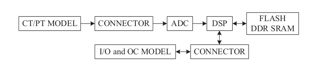
Fig.2 Diagram of the information transmission chain for achieving protection function
(2)Bay-Layer Measurement and Control Function
The input information required for the measurement function is identical to that of the protection function,which includes the input information for sampling and switching status quantity.After processing by the DSP,the system software program packages the processed information into MMS messages and uploads the messages to the MMS network through Ethernet interfaces.Meanwhile,the input for the control function is from the MMS control operation instruction issued by the MMS layer.Once the system software parses the MMS control message,it executes the operation through the I/O and OC modules.Fig.3 illustrates the hardware involved in the transmission chain of the measurement and control information.The transmission chain and hardware are presented as well.

Fig.3 Diagram of information transmission chain for achieving measurement and control function
(3)MU Function
The MU function of the PMMI device can be regarded as a module added to a conventional cable direct-connected protection device.This module can synchronize sampling through interpolation,organize the sampled data into SV messages,and transmit them to the process network in a multicast manner.The input information is consistent with the electrical sampling data of the protection function.The information transmission chain and hardware involved are shown in Fig.4.
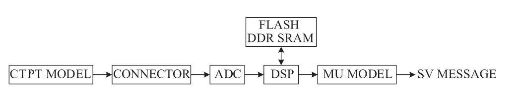
Fig.4 Diagram of information transmission chain for achieving MU function
(4)IT Function
The intelligent terminal function of the PMMI device aligns with the bay-layer protection function in the I/O and OC.The intelligent terminal module arranges GOOSE messages and broadcasts them to the processing network.Alternatively,it receives GOOSE real-time control messages from the process network,and the DSP of the main CPU module parses them before executing the protective switching operation commands through the I/O and OC modules.The intelligent terminal module establishes only a virtual connection with other cross-bay relay protection because the protection function of the device satisfies the bay-layer protection function.A hardware diagram of the information transmission chain is illustrated in Fig.5.
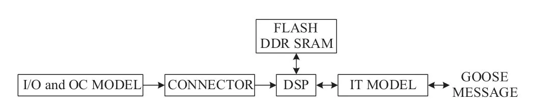
Fig.5 Diagram of information transmission chain for achieving IT function
2 Relay Protection System Based on PMMI Device
To analyze the effect of adopting the PMMI device in IEC 61850-based substations on the relay protection system,we constructed a model of line and busbar protection based on the PMMI device.The transmission path of the protection information was analyzed based on the implementation of the relay protection function.Because the line protection does not require interaction with the switch for information exchange,its transmission chain of protection information is consistent with the information transmission path of the protection function presented in Section 1.2 and thus will not be discussed further.
2.1 PMMI-Based Busbar Protection System Architecture
The integration of the MU and IT functions for each line protection enables busbar differential protection based on the PMMI device to directly access the line information of each bay device from the process network.This reduces the use of secondary cables for bus differential protection and significantly enhances their reliability.Using the typical busbar main wiring of 110 kV IEC 61850-based substations as an example,a primary connection comprises a single busbar segmented connection,where each segment connects one main transformer (T1,T2)and one transmission line (L1,L2).Busbar protection subscribes to SV and GOOSE messages to obtain real-time operating data from bays connected to the busbar.The segment breaker bays and transformers 1 and 2 use the MU and IT all-in-one device (MID),which integrates the MU and IT vertically.Because busbar protection necessitates the cross-bay interaction of information,the information for each bay must be obtained from the process network by subscribing to the SV and GOOSE messages sent by each bay.Subsequently,the busbar determines whether the protection is enacted based on the information obtained and the protection criteria.If the protection start condition is satisfied,then the busbar protection interruption service is initiated and GOOSE messages are sent to the process network.After subscribing to the GOOSE messages sent by the busbar bay,the other bays can control the tripping of the circuit breaker.Fig.6 illustrates the information transmission chain for busbar protection.
2.2 State Transfer Model of Protection System Based on PMMI Device
Both the line and busbar protection operate in three distinct states:normal operation,failure,and maintenance.These states are mutually exclusive and independent of each other.At any moment,line and busbar protection can only occur in one state,and each state can transition to another under specific conditions.This study investigates the stability probability of a relay protection system based on PMMI devices in a particular state.To achieve this,we construct a state-transfer model for line and busbar protection systems based on Markov chain analysis.A statetransfer diagram is shown in Fig.7.
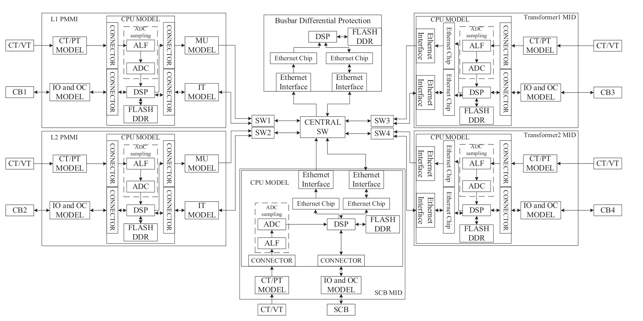
Fig.6 Hardware composition and information transmission chain of busbar protection system based on PMMI device
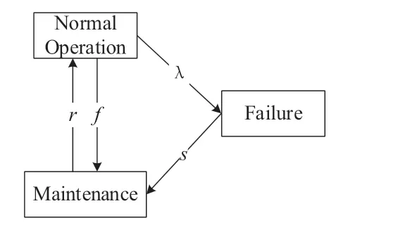
Fig.7 State transfer diagram of line and busbar protection
In Fig.7,“Normal operation” implies that the substation is operating normally,“Failure” implies the failure of the substation,and “Maintenance” means that the substation is undergoing maintenance.Additionally,λrepresents the failure rate of the line or busbar protection system,frepresents the frequency of periodic maintenance for the protection system,rrepresents the maintenance repair rate,andsrepresents the emergency efficiency of maintenance personnel,which indicates the personnel emergency efficiency,i.e.,the probability of dispatching personnel to repair a substation immediately after a failure.The Markov state-transfer probability density matrixAcan be derived from the protection state transfer diagram shown in Fig.7.
Assuming that the stability probability of each state of the line and busbar protection systems is represented byξ=[ξ1,ξ2,ξ3],a relationship exists between the stability probabilityξand transfer probability density matrixA:
The stability probabilities of the line protection and busbar protection systems in normal operation,failure,and maintenance states can be determined based on the relationship between the states expressed in Equation (2).
3 Reliability Analysis Model of Relay Protection System Based on PMMI Device
3.1 Reliability Analysis Model of PMMI
1.FTM for PMMI Device
FTA is a typically used method for calculating system reliability.The basic principle involves identifying the minimum cut set of system failures and constructing an FTM of the system using Boolean algebra or the rank-andfile method.In this method,basic events are assumed to be independent of each other.Hence,the probability of system failure can be expressed as
In Equation (3),nrepresents the number of minimum cut sets in the system fault tree,Ni(0<i≤n)represents each minimum cut set,andPrepresents the probability of system failure.
Fig.1 illustrates the hardware system structure of the PMMI device and its information transmission chain,which is classified into six modules based on their respective completion functions.Based on the FTA method,the minimum cut set of the PMMI device is any single component,and the failure rate of each component is independent of one another.These constitute the basic event of the FTM.Therefore,by utilizing the Boolean algebraic method and Equation (3),the failure rate of the PMMI device can be calculated by determining the failure rate of each “component–module–device” in a stepwise manner.The FTM of the PMMI device is shown in Fig.8.

Fig.8 Fault tree model of hardware system of PMMI device
Because the failure rate of the Ethernet chip is significantly lower,i.e.,differing by eight orders of magnitude from the failure rates of other basic events [24],we disregard the failure rate of the Ethernet chip when constructing the FTM for this device.The events associated with each hardware failure are listed in Table 1.

Table 1 Hardware system fault tree events for vertical integration of protective device
2.Failure Rate Model for Each Component in PMMI Device
As depicted in Fig.1,the PMMI device comprises numerous electronic components that can be broadly categorized into microprocessors,memory modules,integrated circuits,relays,optocoupler components,printed circuit board connectors,and fiber-optic connectors.The microprocessor comprises both a CPU and DSP,whereas the memory includes DDR and FLASH.The integrated circuit is an AD converter,the connector for the printed circuit board is a connector,and the fiber-optic connector is an Ethernet interface.
In the national standard “GJB/Z 299C-2006:Reliability prediction handbook for electronic equipment,” the failure rate calculation models for seven primary components are provided.These components include microprocessors,memory modules,integrated circuits,relays,optocouplers,printed circuit board connectors,and fiber-optic connectors.The calculation models for these components are presented in Table 2 [25].

Table 2 Hardware system fault tree events for VID-PMMI
The quality of a component differs depending on the manufacturer,batch,component structure,and interface form.The failure rate of electronic components varies depending on the temperature of the environment in which they are operated.These factors should be considered when calculating the failure rate of components.In Table 2,λprepresents the electronic component operating failure rate,λbthe electronic component base failure rate,πQthe quality coefficient,πTthe thermal stress coefficient,πVthe voltage stress coefficient,πEthe environmental coefficient,C1andC1the circuit complexity failure rates,andC3the packaging complexity failure rate.TheπLin Equations (4),(5),(6),and (7)is the maturity coefficient,and theπCVCin Equation (6)is the read-write cycle coefficient.In Equation (8),πC1is the contact form coefficient,πCVCthe action rate coefficient,πrthe rated load coefficient,πAthe application coefficient,andπCthe structure coefficient.In Equation (9),πCis the structure coefficient.In Equation (10),πPis the contact coefficient,πKthe insertion and pull-out coefficient,andπCthe jack structure coefficient.In Equation (11),πmis the transmission mode coefficient,πpthe end-face form coefficient,andπLis the connection coefficient.
3.Failure Rate Model for PMMI Device
Based on the schematic diagram of PMMI device components presented in Fig.1 and the PMMI FTM shown in Fig,8,the failure rate of the internal power supply module,CT/PT module,main CPU module,MU module,IT module,I/O,and OC module of the PMMI device can be expressed using Boolean algebra as follows:
whereλpmdenotes the failure rate of modulem,λithe failure rate of componentiin modulem,Nithe number of componentsiin modulem,andnthe number of components in modulem.
Considering the varying importance of each module in the PMMI device and assigning the corresponding weights to each module,the device failure rate can be expressed as shown in the FTM presented in Fig.8.
whereλpT1denotes the operating failure rate of the PMMI device;λpX1denotes the power failure rate;andλpYj(j=1,2,…,5)denotes the failure rates of the CT/PT,main CPU,MU,IT module,and I/O and operation loop modules,respectively;andξj(j=1,2,6…)denotes the weight of each module,where
3.2 Reliability Model for Systems Based on PMMI Devices
1.FTM for Line Protection
The line protection information chain includes the components shown in Fig.2.Using the FTA method,we constructed a line-protection FTM,as illustrated in Fig.9.In this model,T2 represents “line protection failure,” whereas the remaining events are listed in Table 1.
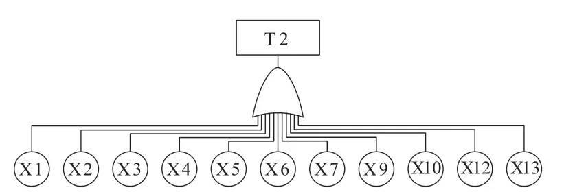
Fig.9 Fault tree model of the hardware system of line protection
Using the Boolean algebraic method,the failure rate of the line protection can be expressed as follows:
wherenidenotes the number of components Xiinvolved in completing the complete set of logic for line protection;andξidenotes the weight of each component,where Σξi=1.
2.FTM for Busbar Protection
The implementation of busbar protection relies on the information acquired from each bay and the interaction of the process network.Each bay operates independently,thus allowing an FTM to be constructed for each bay.By combining the FTM of the process network and the main CPU board for busbar protection,an FTM of busbar protection can be constructed.Fig.6 illustrates that the FTM of each bay can be categorized into two types:the FTM of the line bay using the PMMI device,and the FTM of the segmental breaker bay and transformer bay using the MID.However,because the PMMI device of the line bay utilizes only the MU and IT functions in busbar protection,the actual component type is consistent with that of the MID device when constructing the FTM.Therefore,the bay FTM can be expressed uniformly,as shown in Fig.10,where Y1 indicates a bay failure event.
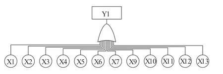
Fig.10 PMMI device merging unit and intelligent terminal function (MID)fault tree
Process network failure refers to a fiber or switch failure,and busbar protection main CPU board failure refers to the failure of each component.These two FTMs are shown in Figs.11 and 12,respectively,where Y6 indicates a process network failure event,Y7 a main bus protection CPU board failure event,X14 a fiber failure event,and Y15 a switch failure event.

Fig.11 Fault tree of process network

Fig.12 Fault tree of bus protection main CPU board
The fault failure rate model for each bay,process network,and bus protection main CPU board can be expressed as follows:
whereλpY1-2denotes the failure rate of the PMMI device’s MU and IT functions at line 1 and line 2 bays;λpY3-5denotes the failure rate of the MID device at the segment breaker,transformer 1,and transformer 2 bays,respectively;λpY6denotes the failure rate of the process network;andλpY7denotes the failure rate of the busbar protection main CPU.
The resulting failure rate of busbar protection can be expressed as
4 Example analysis
4.1 Reliability Calculations for PMMI Device
In accordance with the reliability standard “GJB/Z 299C-2006,” we assume that the device is installed in a general,ground-fixed environment.Additionally,the components used in the device are certified by the China Electronic Components Quality Certification Committee as Class II products,which comply with the corresponding standards or technical conditions and have been stably produced.The microprocessor model used for protection is L138,and the package form is a plastic solder ball array package with thermal resistanceRjc=7 ℃/W [26].The AD converter model used is ADS7056,and the microprocessor and storage are conventional microcomputers.The relay load rateS=1,and the contact load ratingI≤1A.The load is a low-power circuit,and the optocoupler components are light-emitting diodes and photosensitive transistors composed of low-speed switching photocouplers.The actual number of contacts used in the connector is two,and the jack structure is a pinhole.The number of Ethernet cores is two,and the measurement and control function is singlemode transmission,whereas the MU and IT functions are multi-mode transmissions.Finally,the failure rate of the device is considered under ambient temperatures of 30 °C/40 °C/45 °C/60 °C.
Based on the conditions outlined above as well as Equations (1)–(13),the failure rateλmof each module can be calculated from the hardware models listed in Table 2.These rates are,measured in units of ×10-6times/h,are presented in Table 3.

Table 3 Failure rate of each module of PMMI device
The failure rateλpPMMIof the PMMI device in units of failures ×106times/h is calculated using Equation (13).
A power system is repairable and its availability (A)is related to the mean time between failures (MTBF)and mean time to repair (MTTR).This relationship can be expressed as
whereμandλrepresent the repair rate and failure rate of the system,respectively.
The MTTR of the device under PMMI device failure is 24 h.Table 4 presents theAand unavailability (q)of the PMMI device at various temperatures (30 ℃,40 ℃,45 ℃,and 60 ℃),whereq=1 -A.
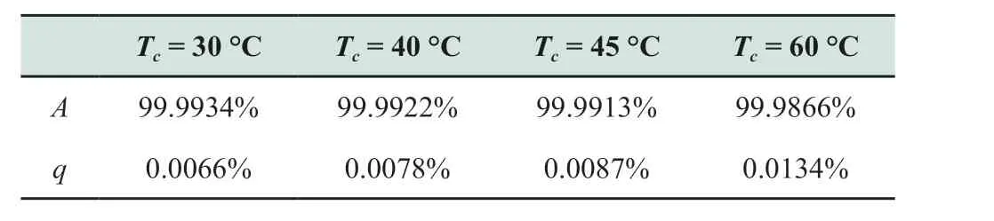
Table 4 Availability and unavailability of hardware system of vertically integrated protective device
Combining Equation (18)and Table 4,the PMMI device exhibited a low failure rate of 2.7578×10⁶times/h under normal operating conditions and a high reliability that yielded an availability of 99.9934%.These results satisfied the reliability requirements of an actual operating device.Additionally,Equation (18)and Table 4 show that the failure rate and unavailability of the PMMI device increased with the operating temperature.AtTc=60 °C,the failure rate and unavailability were approximately 2.02 times higher than those at 30 °C,thus indicating that the reliability of the PMMI device is affected by temperature.Therefore,heat dissipation must be prioritized in the device design process to ensure that the availability and reliability of PMMI devices are effectively improved.
4.2 Sensitivity Analysis of Each Module of PMMI Device
Probabilistic sensitivity analysis was performed in this study to investigate the sensitivity of the PMMI device’s reliability changes to hardware reliability changes for each component of the device.The analysis examines the sensitivity of each module,and the probabilistic sensitivity of each moduleImcan be expressed as
wherePPMMIandPmrepresent the probabilities of stable operation of the device and module,respectivelyPm.Because the device is a series system,the probability of the device operating stably can be expressed as
wherendenotes the number of modulesm.
The sensitivity of the device to each module at ambient temperatures of 30 °C/40 °C/45 °C/60 °C is listed in Table 5.

Table 5 Results of sensitivity analysis
Table 5 shows that,at the same temperature,the main CPU module exhibited greater sensitivity than the other modules and was generally more sensitive than the other modules by 0.01%.This suggests that the main CPU module is more susceptible to changes in device reliability.One can ascribe this to the complexity of the main CPU module components and the fact that it performs most of the functions of the PMMI device.Additionally,Table 5 indicates that,for a certain module,the sensitivity decreased as the ambient temperature increased.The higher the temperature,the more significant was the difference between the highsensitivity modules,e.g.,IY4andIY5were almost equal at 30 °C;however,when the temperature increased to 60 °C,the sensitivity ofIY4was 0.01% higher than that ofIY5.This trend is consistent with the changes in device availability and temperature.Furthermore,the sensitivity of the main CPU module was generally higher than those of the other modules,thus indicating that it is affected more significantly by temperature.Because the main CPU module determines the functionality of the device,one must consider heat dissipation during the design process.
4.3 Reliability Calculation of Protection System Based on PMMI Device
Reliability is a typically used index to describe the dependability of a system and represents the probability that a system will complete a specified function within a specified time.The relationship between reliabilityRsystem(t)and failure rateλsystemcan be expressed as follows:
wheretis the time elapsed since the system began operating.
Fsystem(t),which is the probability of the system failing at timet,can be calculated as
Assuming an operating environment of 40 °C for the relay protection system,the failure rates of the line and busbar protection systems were calculated separately.Subsequently,the reliabilities of the line protection and busbar protection systems were evaluated by usingRsystem(t)andFsystem(t).Table 6 presents the failure rates,reliability,and unreliability of the line protection and busbar protection systems as well as the failure rates of each bay of the busbar protection system,process network,and main CPU of the busbar protection system.
Based on the results,the reliabilities of the line and busbar protection systems within a one-year period were 98.28% and 84.99%,respectively,thus indicating their high reliability.However,after three years,the reliability of the line and busbar protection systems decreased to 94.93% and 61.39%,respectively.Although the reliability of the busbar protection decreased to the initial 72%,the devices,lines,etc.are typically overhauled and replaced during an actual project.After three years,we verified whether the protection system’s reliability during the three-year period still satisfied the actual engineering requirements.
The analysis showed that the reliability of the busbar protection was lower than that of the line protection because of the use of more equipment and the susceptibility of the process network to damage.However,an actual substation undergoes daily overhaul and maintenance,which improves the system reliability relative to the calculated results.
In conclusion,the reliability of the protection system was high within the first year but decreased over time.Nevertheless,the actual project maintenance and overhaul practices ensured that the system reliability satisfied the engineering requirements.
4.4 Analysis of System State Transfer Based on PMMI Device
Based on the use of PMMI devices for line and busbar protection in three states (Normal operation,Failure,and Maintenance),the probability of the system being in a certain state can be calculated using a Markov chain.This calculation considers the emergency efficiency of overhaul personnel after system failure,the repair rate of the system during overhaul,and the frequency of regular overhauls.The specific details are presented in Table 7.
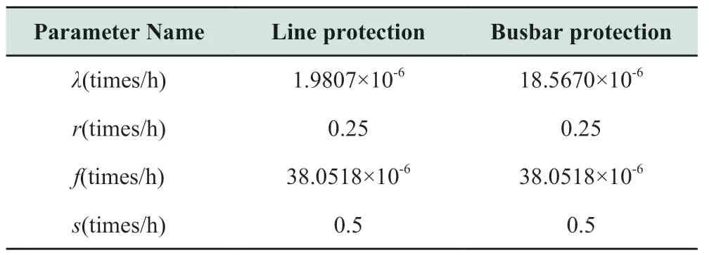
Table 7 Availability and unavailability of hardware system of vertically integrated protective device
Based on the data presented in Table 7,the state-transfer probability density matrixAcan be constructed for both line and busbar protection.Using Equation (2),the probabilities of line protection and busbar protection can be calculated for normal operation,fault,and maintenance states based on the PMMI device.These probabilities are listed in Table 8.
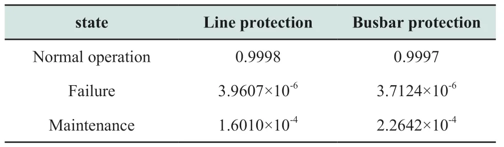
Table 8 Probability density parameters of state transfer for line protection and busbar protection based on PMMI devices
Based on Table 8,the probability of line and busbar protection based on PMMI devices operating normally exceeds 99.9%.In addition,the probability of these devices being faulty is extremely low.These results suggest that a relay-protection system based on PMMI devices is highly reliable.
5 Conclusions
Herein,the construction of the hardware architecture for PMMI devices and the information transmission chain for each function are presented.The construction is based on the functions of conventional protection devices,measurement and control devices,MUs,and ITs,with reference to the hardware architecture of each device.This approach enables the physical and functional vertical integration of devices.To analyze the architecture and reliability of relay protection systems using PMMI devices,we constructed a hardware architecture and information transmission chain for both line and busbar protection based on PMMI devices using the Boolean algebra method.
Additionally,we employed FTA to construct FTMs for PMMI devices,line protection,and busbar protection.Results of arithmetic analysis revealed the high reliability of the PMMI device.Meanwhile,results of sensitivity analysis of the module indicated that the main CPU board was more sensitive to the device reliability.Using a Markov chain,we analyzed the stability probabilities of line and busbar protection in the “Normal operation”,“Failure”,and “Maintenance” states.The results verified the high reliability of relay protection based on PMMI devices.
Acknowledgements
This study was supported by the 2020 Infrastructure Engineering Technology Innovation Project and the “Intelligent Substation” Supporting Technology Research Project (031200WS22200001).
Declaration of Competing Interests
The authors have no conflicts of interest to declare.
 Global Energy Interconnection2023年6期
- Global Energy Interconnection的其它文章
- Over-limit risk assessment method of integrated energy system considering source-load correlation
- Optimal dispatch approach for rural multi-energy supply systems considering virtual energy storage
- Federated double DQN based multi-energy microgrid energy management strategy considering carbon emissions
- Coordinated planning for flexible interconnection and energy storage system in low-voltage distribution networks to improve the accommodation capacity of photovoltaic
- Layered power scheduling optimization of PV hydrogen production system considering performance attenuation of PEMEL
- Application of four machine-learning methods to predict short-horizon wind energy