
Electronic Modulation of Ni-Mo-O Porous Nanorods by Co Doping for Selective Oxidation of 5-Hydroxymethylfurfural Coupled with Hydrogen Evolution
2024-01-22 12:11ShuyiZhengJiaWuKeWangMengchenHuHuanWenShibinYin
物理化学学报 2023年12期
Shuyi Zheng,Jia Wu,Ke Wang,Mengchen Hu,Huan Wen,Shibin Yin
Guangxi Key Laboratory of Electrochemical Energy Materials,College of Chemistry and Chemical Engineering,Guangxi University,Nanning 530004,China.
Abstract: Fossil fuel depletion and environmental deterioration have created an urgent need to develop renewable and clean energy.Biomass,a sustainable organic carbon source,can meet the huge demand for energy and chemicals.Among them,5-hydroxymethylfurfural (HMF) is an important biomass-derived platform molecule,which can be converted into various high-value chemicals.One of its oxidation products,2,5-furandicarboxylic acid (FDCA),is expected to replace terephthalic acid as a raw material for the synthesis of bio-based degradable plastics.The electrooxidation of HMF emerges as a promising green route for preparing FDCA due to its advantages of mild conditions,fast reaction rate,and high selectivity.The theoretical potential of the HMF electrooxidation reaction (HMFOR,0.3 V vs.reversible hydrogen electrode,RHE) is also lower than that of the oxygen evolution reaction (OER,1.23 V vs.RHE).Coupling anodic HMFOR with cathodic hydrogen evolution reaction (HER) is expected to simultaneously produce valuable FDCA and reduce the cell voltage of hydrogen (H2) evolution.However,the construction of efficient and stable bifunctional catalysts for HMFOR-assisted H2 production is still challenging.In this study,Co-doped Ni-Mo-O porous nanorods grown on a nickel foam (Co-NiMoO/NF) is prepared by simple hydrothermal and calcination methods for both HMFOR and HER.Results of electrocatalytic studies indicate that Co-NiMoO/NF exhibits enhanced performance for HMFOR (E10/100 = 1.31/1.37 V vs.RHE) and HER (E-10/-100 = -35/-123 mV vs.RHE) and shows durable HMFOR/HER stability.In particular,Co-NiMoO/NF maintains high FDCA selectivity (~99.2%) and Faradaic efficiency (~95.7%) for 40 successive cycles at 1.36 V vs.RHE for HMFOR.Conversely,Co-NiMoO/NF maintains stable operation at -200 mA∙cm-2 for 50 h with no significant activity attenuation for HER.When coupled as a bifunctional electrode for overall HMF splitting,Co-NiMoO/NF reaches an electric flux of 50 mA∙cm-2 at 1.48 V,which is 290 mV lower than that of the overall water splitting.This confirms that the HMFOR-assisted H2 production over Co-NiMoO/NF significantly reduces the energy consumption.Moreover,the two-electrode system maintains good FDCA selectivity(97.6%) for 10 cycles at 1.45 V,implying good stability of HMFOR-assisted H2 evolution.The remarkable catalytic performance of Co-NiMoO/NF could be due to the introduction of Co,which optimizes the electronic structure of Ni-Mo-O and adsorption behaviors of the reactants,thereby enhancing the intrinsic activity and stability of the catalyst.Meanwhile,the porous nanorod structure enhanced the mass transport of substrates and desorption of bubbles,thereby elevating the HMFOR/HER kinetics.This study provides useful insights for designing efficient and durable bifunctional catalysts for HMFOR and HER.
Key Words: 5-Hydroxymethylfurfural oxidation reaction; Hydrogen evolution reaction; Catalyst; Porous structure;Electronic structure
1 Introduction
Fossil energy shortage and greenhouse effect are the global challenges for human beings,the utilization and upgrading of sustainable biomass is an available solution1–4.5-Hydroxymethylfurfural (HMF) is one of the most important biomass-derived platform compounds,which can be transformed into a variety of chemical products,including the high-value 2,5-furandicarboxylic acid (FDCA),is a building block used to produce the degradable plastic polyethylene furanoate (PEF)5–9.Generally,the conversion of HMF to FDCA mainly relies on the conventional oxidation methods,requiring harsh conditions10–12.Recently,electrochemical HMF oxidation reaction (HMFOR,HMF + 6OH-→ FDCA + 4H2O + 6e-,0.3 V)as a mild and environmental-friendly method that has attracted much attention.And it possesses smaller theoretical potential than that of the anodic oxygen evolution reaction (OER,4OH-→ O2+ 2H2O + 4e-,1.23 V).Therefore,coupling anodic HMFOR with cathodic HER is expected to produce the valuable FDCA and reduce the cell voltage of hydrogen (H2) collection,which is favorable for the improvement of energy efficiency and economic benefits.
Up to now,there are tremendous efforts focus on exploring bifunctional catalysts for both HMFOR and HER.Noble catalysts possess satisfactory bifunctionality13,14,but the high price and low reserves hinder their large-scale application.Consequently,it demands to explore highly active non-precious metal catalysts,among which Ni-Mo materials have been widely studied because of the synergistic effect between multiple components.According to literatures,Ni-Mo-O derived catalysts exhibited impressive activities for HER in alkaline media,where the oxides promote the cleavage of the H―OH bond and the nearby metal facilitates the adsorption and recombination of the resulting*H intermediates into molecular H215–17.Unfortunately,their HMFOR catalytic performance is unsatisfactory.Although high valance Ni shows good selectivity to HMF,the oxidation potential of Ni2+/Ni3+is limited to ~1.36 V,resulting in relatively high energy input18.Therefore,it is necessary to design Ni-Mo bifunctional catalysts with advanced HMF electrolysis-assisted H2production at low potentials.
It is reported that Co-based catalysts have a much lower onset potential for HMFOR due to the smaller oxidation potential of Co2+/Co3+(~1.14 V)19.Previous works have shown that heteroatom-doping plays an effective role in improving the catalytic performances of multi-metal compounds without changing their chemical composition,which can tune the electronic structure and rearrange the valence electrons of host materials and further modulate the adsorption energies of intermediate species20–25.For instance,Wuetal.reported Codoped NiO/NiFe2O4mixed oxide mesoporous nanosheet array as a bifunctional catalyst for overall water splitting,due to the incorporation of Co2+into Ni-Fe mixed oxide,it can manipulate the electronic structure to enhance the conductivity and activate the Ni sites at low overpotentialviacharge transfer effect26.Besides,the rapid mass transport of organic molecules and gas diffusion are also important for both HMFOR and HER.Hence,the structural design,such as porous structure,has been identified as a useful avenue to enhance the catalytic activity27.
This work prepares the Co-doped Ni-Mo-O porous nanorod(denoted as Co-NiMoO/NF) as a high-efficient bifunctional catalyst for both HMFOR and HER.In 1.0 mol∙L-1KOH with 10.0 mmol∙L-1HMF electrolyte,it exhibits low potentials of 1.31/1.37 V (@10/100 mA∙cm-2) and -35/-123 mV(@-10/-100 mA∙cm-2) for HMFOR and HER,respectively.Notably,it can maintain good FDCA selectivity (~99.2%) even after 40 continuous conversion cycles at 1.36 V.As a bifunctional catalyst,it can drive the HMF electrolysis-assisting H2production at 1.48 V to reach 50 mA∙cm-2.Co-NiMoO/NF exhibits good catalytic activity,which could be due to the following advantages: (i) Electron structure configuration can be optimized by Co doping to elevate the HMFOR/HER intrinsic activity; (ii) Porous nanorod structure with large specific surface is facile to the mass transport and the desorption of bubbles.This work thus provides an avenue to prepare bifunctional catalyst for highly efficient biomass oxidation coupled with H2production.
2 Experimental
2.1 Chemicals
All chemicals were used directly without further purification,including 5-hydroxymethylfurfural (HMF,AR,> 99%),2,5-furandicarboxylic acid (FDCA,AR,98%),5-hydroxymethyl-2-furancarboxylic acid (HMFCA,AR,98%),2,5-diformyfuran(DFF,AR,> 98%),5-formyl-2-furancarboxylic acid (FFCA,AR,> 98%),anhydrous ethanol (C2H6O,AR,99.7%),hydrochloric acid (HCl,AR,36%–38%),potassium hydroxide(KOH,AR,≥ 85%),sodium molybdate (Na2MoO4∙2H2O,AR,99%),nickel nitrate hexahydrate (Ni(NO3)2∙6H2O,AR,≥ 98%),cobalt nitrate hexahydrate (Co(NO3)2∙6H2O,AR,99%),ammonium formate (CH5NO2,AR,≥ 99%) ,methanol (CH4O,LC,≥ 99.9%) and nickel foam (NF).The deionized water (DW)with a resistivity of 18.2 MΩ was used for all experiments.
2.2 Synthesis of Co-NiMoO/NF
Ni foam was ultrasonically cleaned in 1.0 mol∙L-1HCl,ethanol and DW sequentially.2.0 mmol Na2MoO4∙2H2O,2.0 mmol Ni(NO3)2∙6H2O and 0.3 mmol Co(NO3)2∙6H2O were dissolved into a mixed solution of 30 mL H2O,then poured it into a 50 mL Teflon-lined autoclave with two piece of pretreated NF (1 cm × 6 cm).Next,a standard hydrothermal procedure was carried out at 160 °C for 8 h.After cooling to room temperature,the precursors were thoroughly cleaned with DW and ethanol,then dried in a vacuum for 12 h at 60 °C.Finally,the precursors were calcinated in H2/Ar (5%/95%) atmosphere at 450 °C for 2 h with a heating rate of 5 °C∙min-1,and the obtained samples were named Co-NiMoO/NF.For Co doping content,the amount of Co(NO3)2∙6H2O was varied from 0.1 to 0.4 mmol,and keeping other parameters as constant.NiMoO/NF,Co-NiO/NF and Co-MoO/NF were synthesized similarly without cobalt,molybdenum and nickel sources,respectively.
2.3 Characterization
X-ray diffraction (XRD,SmartLab3KW,Rigaku,λ=0.154056 nm,Japan),X-ray photoelectron spectroscopy (XPS,AlKαradiation (12 kV,6 mA),Thermo Fisher Scientific,USA),and Raman spectroscopy (Raman,LabRAM HR Evolution,HORIBA Jobin Yvon,France) were executed to detect the crystal phase,surface properties and microstructure.The morphology was observed by scanning electron microscopy(SEM,SU8220 Hitachi,Japan) and transmission electron microscopy (TEM,FEI Talos-F200S,Thermo Fisher Scientific,USA).The metal content was investigated by inductively coupled plasma mass spectrometry (ICP-MS,Agilent 7500x,USA).The porous structure characteristics were evaluated by N2adsorption/desorption analysis at 353 K and the specific surface areas were calculated by Brunauer-Emmett-Teller (BET)method performed on a V-Sorb 2800 (Gold APP Instruments Corporation,China).
2.4 Electrochemical measurements
The HER,OER,and HMFOR activity tests were performed on a Gamry Interface 1010E electrochemical workstation under a three-electrode system with stirring.The NF supported samples (1 cm × 1 cm),reversible hydrogen electrode (RHE) and graphite rod were used as the working electrode,reference electrode,and counter electrode,respectively.Linear sweep voltammetry (LSV) was measured with the scan rate of 5 mV∙s-1in an electrolyte of 1.0 mol∙L-1KOH with and without 10.0 mmol∙L-1HMF.IRcompensation was employed in each electrochemical measurement.Tafel slope values of all the electrodes were calculated by the formula ofη=b× log|j| +a,whereais the corresponding intercept,jis the current density,bis the Tafel slope value,andηis the overpotential.Electrochemical impedance spectroscopy (EIS) tests were measured over a frequency range from 0.1 Hz to 100 kHz.Electrochemical surface area (ECSA) was calculated from the electrochemical double-layer capacitance (Cdl) by using cyclic voltammetry (CV) at different scan rates in non-Faradaic region.The relationship between them can be expressed by the following equation: ECSA =Cdl/Cs,andCsis the specific capacity of electrode which is usually taken as 0.04 mF∙cm-2in alkaline media.From this,Cdlis positively correlated with ECSA,which could indicate the catalytic active center of catalyst.Generally,the higher theCdlvalue,the richer the catalytic active center,and the better the activity of catalyst.The potential window was selected in the non-faradic region (0.35–0.45 Vvs.RHE),and CV was performed at various scan rates(20,40,60,80 and 100 mV∙s-1).Then,the difference of current density changes (J=Ja-Jc) under overpotential was plotted according to the scan rate.Based on these results,Cdlvalue can be obtained from the slope by fitting the straight line.Meanwhile,the HMFOR and HER LSV curves were normalized by ECSA,and the current density was divided byCdlvalue.It should be noted that all the potentials mentioned in this work are the RHE.
2.5 High performance liquid chromatography analysis
To analyze the products quantitatively and calculate the corresponding Faradaic efficiency (FE),the oxidation products of HMF were implemented in high performance liquid chromatography (HPLC) on a Shimadzu Prominence-I LC-2030C at ambient temperature.20.0 μL of the electrolyte solution was taken out from electrolyzer by a microsyringe,then diluted with 960 μL DW and 20.0 μL 1.0 mmol∙L-1HCl.The HPLC was fitted out with a Shimadzu Shim-pack GIST column(5 μm C18,4.6 × 250 nm) and a UV-Vis detector (λ= 265 nm).The eluent consisted of 70% 5.0 mmol∙L-1ammonium and 30% liquid chromatography grade methanol.The identification and quantification of the reactants,intermediates and products were determined from calibration curves by applying the standard samples of known concentrations (Fig.S1,Supporting Information).
The conversion (%) of HMF and selectivity (%) of oxidation products were calculated according to the following equations:
The FE of FDCA was calculated by the following equations:
Accordingly,the theoretical hydrogen volume corresponding to complete conversion of HMF to FDCA can be calculated using the following equation:
whereFis the Faraday constant (96485 C∙mol-1),andVmis the molar volume of gas.
3 Results and discussion
3.1 Preparation and characterization analysis
Co-NiMoO/NF is prepared by a two-step process (Fig.1a).Firstly,Co-doping NiMoO4∙xH2O nanorods are directly grown on NFviahydrothermal treatment (Fig.S2).Secondly,the precursors are calcinated to obtain the Co-NiMoO/NF.SEM shows nanoparticles formed and attached on the Co-NiMoO/NF nanorods (Fig.1b–d),which is due to the compositional transformation of precursor after calcination treatment.NiMoO/NF is fabricated for comparison,it also displays nanorods with nanoparticles,suggesting that the structure of NiMoO/NF is well-preserved after Co doping (Fig.S3).
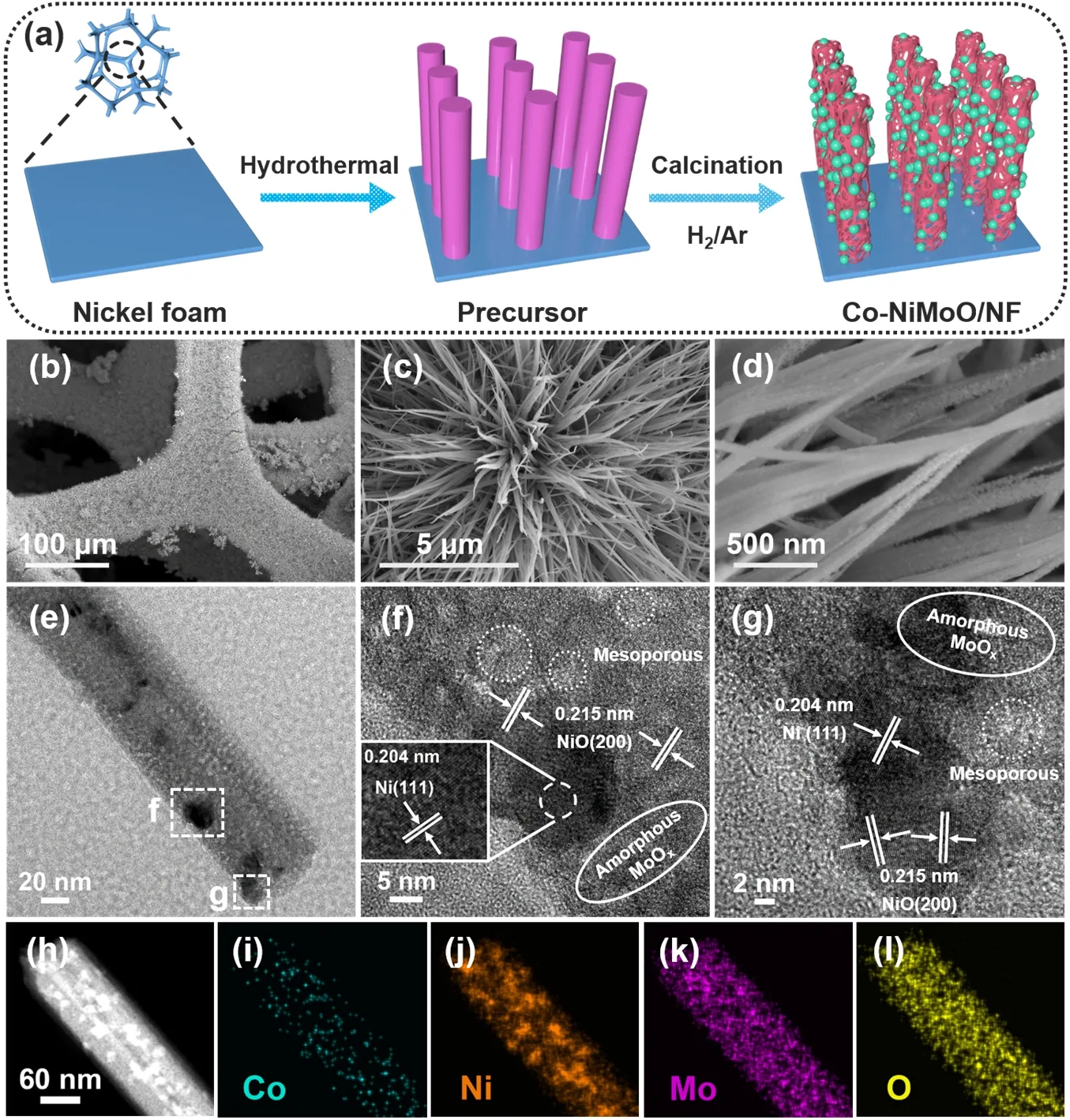
Fig.1 (a) Schematic illustration for preparing Co-NiMoO/NF; (b–d) SEM; (e–g) TEM and HRTEM;(h–l) ADF-STEM and EDX elemental mapping images of Co-NiMoO/NF.
XRD is investigated to analyze their crystal structures.The precursor corresponds well to NiMoO4∙xH2O (PDF#13-0128)(Fig.S4a).For Co-NiMoO/NF and NiMoO/NF,both Ni(PDF#04-0850) and NiO (PDF#71-1179) are included,while no diffraction peaks can be assigned to Mo oxides,suggesting its poor crystallinity (Fig.S4b).The diffraction peaks of Co-NiMoO/NF slightly shift to a higher angle compared to NiMoO/NF (Fig.S4b,inset),which may be due to the different ionic radius of Co2+(74.5 pm) and Ni2+(69 pm) that leads to the enlargement of NiO lattice fringes.The Raman spectroscopy shows the peaks of Mo=O (286 and 372 cm-1),Mo3―O (340 and 720 cm-1) and MoOx(818,890,and 938 cm-1) (Fig.S5),indicating the presence of molybdenum compound15,28,29.And the peaks of Co-NiMoO/NF are similar to that of the pure NiMoO/NF,which also indicates the successful doping of Co30,31.
The fine structure of Co-NiMoO/NF is further verified by TEM.Fig.1e displays Ni nanoparticles randomly dotted on the nanorods.High-resolution TEM (HRTEM) image reveals the mesoporous structure in Co-NiMoO/NF,the lattice fringes with the interplanar distance of 0.204 and 0.215 nm can be assigned to the (111) plane of Ni,and the (200) plane of NiO,respectively(Fig.1f,g).And there are some regions without lattice fringes,which can be attributed to the amorphous phase of MoOx.
Annular dark field scanning TEM (ADF-STEM) and energy dispersive X-ray spectroscopy (EDX) elemental mapping images reveal that the Ni,Co,Mo and O elements are evenly distributed on the nanorod (Fig.1h–l & Fig.S6).The Co content is about ~8.46% (mass fraction),close to the ICP-MS results(Table S1),further confirming that Co atoms are successfully doped into the nanorods.Besides,high-angle annular dark field(HAADF) image proves the presence of porous structure on the nanorods (Fig.S7).The porosity of Co-NiMoO/NF is then characterized by BET method (Fig.S8).Both Co-NiMoO/NF and NiMoO/NF show a typical IV type N2adsorption/desorption isotherm curves with H3-shaped hysteresis loops,indicating the existence of mesoporous.The surface area of Co-NiMoO/NF is 66.35 m2∙g-1,which is evidently higher than that of NiMoO/NF(48.34 m2∙g-1).Meanwhile,as seen from the pore size distribution,the mesoporous are dominate in all samples and their diameters are mainly in the range of 8–11 nm.The peak of Co-NiMoO/NF at around 8–11 nm is significantly higher than that of NiMoO/NF,indicating that more pores in this range are produced after Co doping,thus increasing the BET specific surface area.The influence of Co-doping on the BET specific surface area of catalysts is consistent with the former studies32,33.Notably,such porous nanorods possess large specific surface areas and abundant pores,which may facilitate the mass transfer of organic molecules and the escape of bubbles,thereby enhancing the reaction kinetics34.
The elemental compositions and chemical valence states are explored by XPS measurement.The XPS survey pattern confirms the Co,Ni,Mo and O elements exist in Co-NiMoO/NF(Fig.S9).For Co 2pspectrum (Fig.2a),two peaks of Co2+at 781.1 and 796.8 eV are attributed to the Co 2p3/2and Co 2p1/2,and a pair of the satellite peaks located at 786.1 and 802.3 eV,respectively.By curve fitting of the Ni 2pspectrum (Fig.2b),the peaks at 852.0/869.5 eV,855.3/872.9 eV and 861.2/879.3 eV corresponded to the Ni0,Ni2+and satellite peaks,respectively.And the Mo 3dspectrum (Fig.2c) reveals that Mo component has three typical valence states,whose peaks are located at 228.8/231.9,229.8/233.0,and 231.7/234.8 eV,which are equivalent to Mo4+,Mo5+and Mo6+,respectively.Moreover,the O 1sspectrum displays three subpeaks of 529.7 eV (metal―O bond),530.7 eV (oxygen in OH-species) and 532.1 eV (surfaceadsorbed H2O molecules) (Fig.2d).These results further demonstrate the successfully preparation of Co-NiMoO/NF.Besides,the binding energy of Ni 2pand Mo 3dof Co-NiMoO/NF has a negative shift compared to NiMoO/NF,which could be due to the electronegativity difference of Co,Ni and Mo that induces the electron transfer between cations and a change in electronic configuration.This phenomenon indicates that there is electronic interaction after Co doping,which may affect the adsorption/desorption energy of substances and intermediates,thereby enhancing the catalytic activity35,36.

Fig.2 XPS spectra of (a) Co 2p,(b) Ni 2p,(c) Mo 3d and (d) O 1s.
3.2 HMFOR performance
The HMFOR activity is tested in a typical three-electrode system with 1.0 mol∙L-1KOH and 10.0 mmol∙L-1HMF as electrolyte.The effect of the Co dopant concentration (Fig.S10)and calcination temperature (Fig.S11–S13) on HMFOR activity are studied,and the best HMFOR activity is achieved at 0.3 mmol Co addition and then calcinated at 450 °C.Moreover,the Co-doped NiMoO/NF samples are consistently better than NiMoO/NF,indicating that the modulation of electronic configuration on NiMoO/NF after Co doping has a positive effect on HMFOR.Specifically,Co-NiMoO/NF only requires 1.31 and 1.37 V to drive 10 and 100 mA∙cm-2,respectively,which is lower than these of NiMoO/NF (E10/100= 1.34/1.48 V),NF(E10/25= 1.38/1.43 V) (Fig.3a),and Co-NiMoO4/NF (E10/50=1.36/1.39 V) (Fig.S14).And the performance of Co-NiMoO/NF is competitive with many reported catalysts listed in Table S2.Besides,in contrast to Co-NiO/NF and Co-MoO/NF,the enhanced performance of Co-NiMoO/NF implies the synergistic catalytic effect of Ni-Mo oxides being beneficial for boosting the HMFOR activity (Fig.S15).Tafel plots of catalysts are then investigated to obtain insights into the HMFOR kinetics.The Tafel slope of Co-NiMoO/NF is 34.09 mV∙dec-1,which is smaller than that of pure NiMoO/NF (65.91 mV∙dec-1),demonstrating the faster HMFOR kinetics after Co doping(Fig.3b)37.The EIS measurement also discloses that Co-NiMoO/NF has a much smaller charge transfer resistance (Rct)than those of other samples (Fig.3c),suggesting the quick electron transfer for HMFOR.
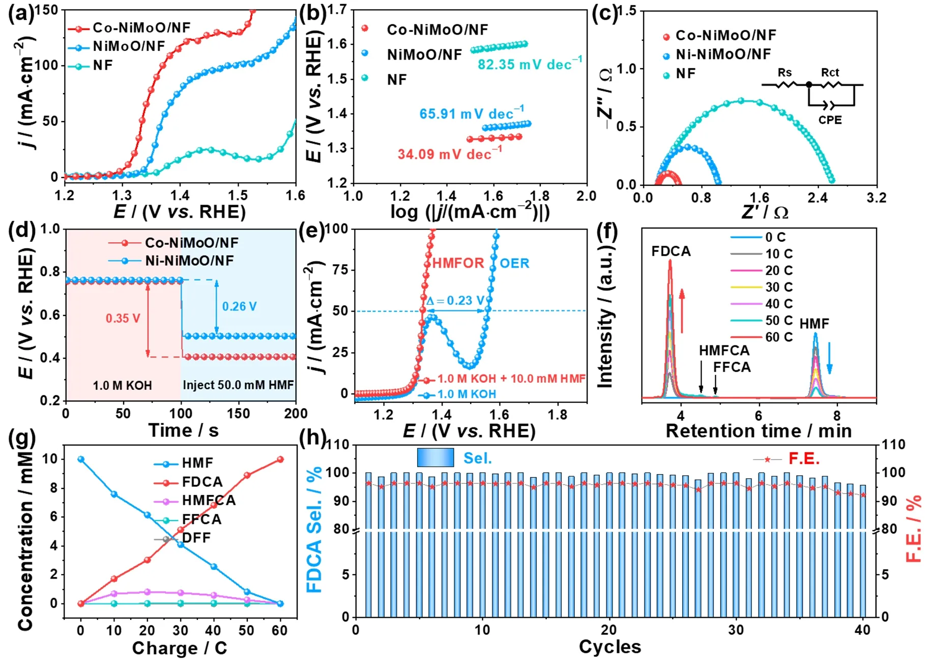
Fig.3 (a) LSV curves of Co-NiMoO/NF and other samples for HMFOR; (b) Tafel slopes; (c) Nyquist plots; (d) OCP curves of Co-NiMoO/NF and NiMoO/NF in 1.0 mol∙L-1 KOH and injecting 50.0 mmol∙L-1 HMF subsequently; (e) LSV curves for Co-NiMoO/NF in 1.0 mol∙L-1 KOH with and without 10.0 mmol∙L-1 HMF; (f) HPLC traces of HMFOR catalyzed by Co-NiMoO/NF; (g) Conversion of HMF and yield of oxidation products during the chronoampermetry test; (h) Selectivity and FE of FDCA for Co-NiMoO/NF based three-electrode system for 40 cycles.
The open-circuit potential (OCP) can reflect the variation of absorbates in the Helmholtz layer which is recorded to evaluate the HMF adsorption behavior on the catalyst’s surface (Fig.3d).When injecting 50.0 mmol∙L-1HMF into 1.0 mol∙L-1KOH,a significant decrease of OCP is observed on Co-NiMoO/NF(0.35 V) than that on NiMoO/NF (0.26 V),suggesting stronger surface adsorption of HMF after Co doping36.This indicates that Co-doping can effectively regulate the adsorption of HMF on NiMoO/NF,which is beneficial for lowering the reaction barrier and accelerating the HMFOR kinetics.
Furthermore,to prove the superiority of replacing OER with HMFOR in an alkaline water electrolyze,the LSV curves of catalyst for HMFOR (10.0 mmol∙L-1HMF) and OER (without HMF) are compared (Fig.3e).Co-NiMoO/NF only needs 1.33 Vvs.RHE to reach the current density of 50 mA∙cm-2for HMFOR,which is significantly lower than that of OER (1.56 Vvs.RHE),indicating that HMFOR is more favorable than OER on Co-NiMoO/NF electrode.
The FDCA yield is a crucial aspect for HMFOR.Since HMF contains a hydroxyl group and a carbonyl group,its oxidation process generally follows two pathways (Fig.S16)8.Path I is that the hydroxyl group is firstly oxidized to carbonyl group to form DFF,and Path Ⅱ is that the carbonyl group is preferentially oxidized to carboxyl group to form HMFCA.Next,both HMFCA and DFF are further oxidized to FFCA and form FDCA eventually.For HMF conversion experiment,it is important to select an appropriate potential.Because different potential determines different initial current density,and the energy consumption also needs to be considered.The electrooxidation of HMF by Co-NiMoO/NF is then carried out at 1.35,1.36,and 1.40 V,respectively,for equivalent electrolysis time.At the end of electrolysis,the Co-NiMoO/NF at 1.36 V displays the HMF conversion,FDCA selectivity,and FE are 100%,99.9%,and 96.4%,respectively,which are significantly higher than that at 1.35 V (100%/74.5%/71.9%),while slightly lower than that at 1.40 V (100%/100%/96.5%) (Fig.S17).Hence,selecting 1.36 V can ensure that HMF is converted into FDCA efficiently and meet the concept of energy conservation (Fig.S18).The change of HMF and intermediates concentration is detected by HPLC(Fig.3f).Along with the increase of charge passed,the feedstock HMF decreases and the product FDCA increases gradually(Fig.3g).Interestingly,the intermediates of HMFCA and FFCA can be observed except DFF,suggesting that the Co-NiMoO/NF-determined HMFOR process mainly follows the Path II.Besides,NiMoO/NF and NF display the HMF conversion,FDCA selectivity,and FE are 99.0%/76.7%/74.0% and 18.1%/3.86%/3.73%,respectively,which are lower than that of Co-NiMoO/NF (Fig.S19).Especially,the amount of charge consumed on NiMoO/NF and NF are less than the theoretical charge of 60 C (Fig.S20).Therefore,it means that Co-doping can improve the conversion and selectivity towards HMFOR,the HMFOR activity of NF is limited,and the high HMFOR activity of catalyst comes from its supported Co-NiMoO nanorods.
In addition,stability is also an important criterion for evaluating the performance of catalysts.To examine the durability of Co-NiMoO/NF,it is performed at 1.36 V for 40 cycles and theI-tcurves show negligible degradation (Fig.S21).Co-NiMoO/NF maintains good activity and stability for HMF conversion (~100%),FDCA selectivity (99.2%),and FE(95.7%) (Fig.3h).Its remarkable catalytic performance is better than most of the reports in literature (Table S3).
To further understand the HMFOR process of Co-NiMoO/NF,it is necessary to analyze the information of valence state changes before and after electrolysis by XPS (Fig.S22).The appearance of Ni3+peaks (856.9/874.6 eV) in Ni 2pafter HMFOR stability test could be due to the formation of hydroxyl hydroxide38–40.In contrast to the O 1sspectrum of pristine sample,the strength of metal―O decreased sharply accompanied by the increasing of O―H in the post sample,revealing a transformation of Ni―O to Ni―OOH41,42.While,the signal of Mo in Mo 3ddisappeared,which could be due to the surface restructured hydroxyl hydroxide that covers the MoOx.
To investigate the instinct reasons of this phenomenon,more physical characterizations are carried out.ICP-MS results show that the Mo content is almost unchanged after electrolysis (Table S1).XRD result indicates that the crystal structure of Co-NiMoO/NF maintained well after HMFOR stability test,confirming the MoOxis preserved (Fig.S23).SEM image shows that the surface of nanorods becomes rough compared with the original one,which may be due to the formation of hydroxyl hydroxide (Fig.S24).TEM and HRTEM images indicate that there is a thin amorphous layer (~5 nm) on the edge of Co-NiMoO/NF nanorod,providing an additional evidence for the formation of NiOOH on the surface (Fig.S25).Raman result exhibits that there is a characteristic peak at ~560 cm-1,ascribed to NiOOH in the sample after electrolysis,further confirming the generation of NiOOH (Fig.S26)43,44.And two peaks located at around 510 and 1060 cm-1belong to the first-order longitudinal optical (LO) and the frequency doubled mode (2LO) of NiO,respectively45,46.From the above analysis,it can be inferred that hydroxyl hydroxide is formed on the surface of Co-NiMoO/NF nanorods after HMFOR stability test,which serves as active species for HMFOR,and covers the MoOx39,40,47.
3.3 HER performance
The activity of HER is also tested in the above three-electrode system.The doping concentration and calcination temperature experiments show that the catalyst obtained by adding 0.3 mmol Co and calcining at 450 °C exhibits the best HER activity(Fig.S27 & Fig.S28).The performance of Co-NiMoO/NF in 1.0 mol∙L-1KOH with and without 10.0 mmol∙L-1HMF is almost the same,suggesting the presence of HMF has miniscule impact on HER performance (Fig.4a).Co-NiMoO/NF needs-35 and -123 mV to achieve -10,and -100 mA∙cm-2,which is better than Co-NiMoO4/NF (-232/-331 mV) (Fig.S29),NiMoO/NF (-46/-158 mV),NF (-313/-449 mV),and close to Pt/C/NF (-22/-95 mV) (Fig.4b-c),as well as most of the reported non-noble HER catalysts (Table S4).This indicates that the HER activity of Co-NiMoO/NF is improved after Co doping,which could tune the electronic structure to influence the adsorption of HER intermediates48.Besides,Co-NiMoO/NF exhibits the best HER performance compared with Co-NiO/NF and Co-MoO/NF,further suggesting the synergistic effect of Ni-Mo oxides is also favor for HER (Fig.S30).The corresponding Tafel slope of Co-NiMoO/NF (52.72 mV∙dec-1) is smaller than that of NiMoO/NF (65.56 mV∙dec-1) (Fig.4d),which may be ascribed to the porous nanorods structure that promotes the desorption of bubbles49.According to the classic theory50,51,HER in alkaline media proceeds in two mechanisms: Volmer-Heyrovsky and Volmer-Tafel.Although the Tafel slope alone is insufficient to determine the specific mechanism,the reduced Tafel slope of Co-NiMoO/NF compared with NiMoO/NF suggests that the Co doping is conducive to speed up the Volmer step in HER kinetics52,53.Meanwhile,Co-NiMoO/NF has a smaller charge transfer resistance (Rct) than that of NiMoO/NF(Fig.4e),demonstrating its speedy charge transfer for HER.This could be due to the strong electronic interaction that promotes electron transfer after Co doping54.Besides,the long-term durability of Co-NiMoO/NF for HER is tested at -200 mA∙cm-2,which can work for 50 h without significant attenuation (only 95 mV) (Fig.4f).According to the XPS and SEM results (Fig.S31 & Fig.S32),the nanorod structure keeps well and the valence state of elements is basically unchanged,proving its good HER stability.

Fig.4 (a) LSV curves of HER for Co-NiMoO/NF in 1.0 mol∙L-1 KOH with and without 10.0 mmol∙L-1 HMF; (b) LSV curves of Co-NiMoO/NF and other samples for HER; (c) Histogram of corresponding HER overpotentials at -10 mA∙cm-2; (d) Tafel slopes; (e) Nyquist plots;(f) I-t curve of Co-NiMoO/NF at -200 mA∙cm-2 for HER stability,insert is the LSV curves before and after HER stability tests.
To further study the reasons of the good catalytic activity of the prepared catalysts,the ECSA is evaluated by theCdlvalue obtained at different scan rates of CV curves (Fig.S33a).Co-NiMoO/NF possesses a largerCdlvalue (67.94 mF∙cm-2) than that of NiMoO/NF (51.86 mF∙cm-2) (Fig.S33b),illustrating the enriched active sites resulting from the Co substitution and the unique morphology with porous nanorods.The HMFOR and HER LSV curves are further normalized by ECSA (Fig.S33c,d),Co-NiMoO/NF still exhibits better intrinsic activity than NiMoO/NF,further suggesting the advantage of Co doping.
3.4 Integrated HMFOR and HER
Considering its good performance for both HMFOR and HER,the Co-NiMoO/NF can be used as the anode and cathode in a Helectrolyzer to evaluate for overall HMF splitting (OHMFS)(Fig.5a & Fig.S34).The assembled system only needs 1.48 V to reach 50 mA∙cm-2for OHFMS,which is ~290 mV smaller than that of the overall water splitting (Fig.5b),reflecting the superiority of energy conservation.It is also superior to the performance of NiMoO/NF | NiMoO/NF (1.52 V to reach 50 mA∙cm-2) (Fig.S35).Subsequently,it is further carried out at 1.45 V to drive HMFOR-assisting H2production,and the concentration of intermediates during the electrolysis are shown in Fig.5c.At the end of electrolysis,the final electrolyte solution becomes colorless compared to the initial yellow solution (Fig.5d).Co-NiMoO/NF exhibits the HMF conversion,FDCA selectivity,and FE are 100%,98.7%,95.2%,respectively.Besides,the volume of collected H2coincides well with the theoretical amount calculated by the passed charge during the whole chronoamperometry process,confirming the almost 100% FE for H2evolution in this integrated system (Fig.5e &Fig.S36).Then,Co-NiMoO/NF | Co-NiMoO/NF is tested for 10 successive electrolysis,and it can still keep ~100% HMF conversion,97.6% FDCA selectivity and 94.1% FE (Fig.5f &Fig.S37),further proving its good stability.The above studies display that Co-NiMoO/NF as bifunctional catalyst has certain application prospects which can highly selectively oxidize HMF coupled with H2evolution.
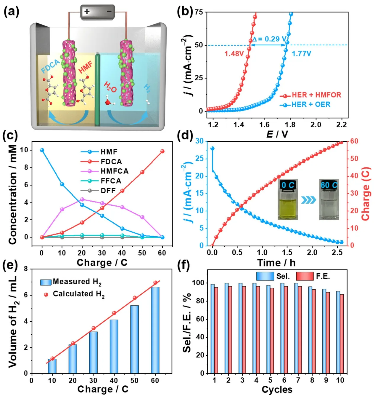
Fig.5 (a) Schematic illustration of Co-NiMoO/NF | Co-NiMoO/NF electrolyzer for both HMFOR and HER; (b) LSV curves of Co-NiMoO/NF ||Co-NiMoO/NF in 1.0 mol∙L-1 KOH with and without 10.0 mmol∙L-1 HMF; (c) Conversion of HMF and yield of its oxidation products during the chronoampermetry test; (d) I-t curves for Co-NiMoO/NF || Co-NiMoO/NF at 1.45 V by passing the charge of 60 C; (e) HER FE of Co-NiMoO/NF as cathode; (f) HMF conversion,FDCA selectivity and FE for Co-NiMoO/NF | Co-NiMoO/NF kept at 1.45 V for 10 cycles.
4 Conclusions
In summary,the bifunctional Co-NiMoO/NF catalyst has been prepared through hydrothermal and calcination methods.It shows remarkable activity for HMFOR (E10/100= 1.31/1.37 V)and HER (E-10/-100= -35/-123 mV).It withstands 10 successive runs at 1.45 V and maintains good activity for HMF conversion(~100%),FDCA selectivity (97.6%),and FE (94.1%).The reason could be attributed to the Co-doping and the porous nanorod structure that tunes the electronic structure and facilitates the transport of organic molecules and the desorption of bubbles,thereby improving the intrinsic activity and reaction kinetics.This work is expected to shed light on the rational design and synthesis of non-precious metal catalysts for biomass conversion with H2production.
Author Contributions:Conceptualization,Shuyi Zheng,Jia Wu,Ke Wang and Shibin Yin; Methodology,Shuyi Zheng,Jia Wu,Ke Wang and Mengchen Hu; Validation,Shuyi Zheng,Jia Wu and Ke Wang; Formal Analysis,Shuyi Zheng,Jia Wu and Ke Wang; Investigation,Shuyi Zheng,Jia Wu,Ke Wang and Mengchen Hu; Resources,Shibin Yin and Huan Wen; Data Curation,Shuyi Zheng; Writing – Original Draft Preparation,Shuyi Zheng; Writing – Review & Editing,Shibin Yin and Jia Wu; Visualization,Shuyi Zheng; Supervision,Shibin Yin;Project Administration,Shibin Yin and Huan Wen; Funding Acquisition,Shibin Yin.
Supporting Information:available free of chargeviathe internet at http://www.whxb.pku.edu.cn.

- 物理化学学报的其它文章
- Recent Advances in Self-Supported Transition-Metal-Based Electrocatalysts for Seawater Oxidation
- 用于高灵敏快速核酸检测的荧光碳点
- Introducing Novel,Multiple Cd Coordination Modes into Gold Nanoclusters by Combined Doping for Enhancing Electrocatalytic Performance
- 电催化二氧化碳还原催化剂、电解液、反应器和隔膜研究进展
- 利用多氟丙烯酸酯添加剂提升准二维钙钛矿发光二极管性能
- 电子自旋效应在电催化剂中的作用