
Investigations of the mechanical response of dummy HTPB propellant grain under ultrahigh acceleration overload conditions using onboard flight-test measurements
2024-03-20 06:43YimingZhngNingfeiWngWeihuRnWngLongBiYiWu
Defence Technology 2024年2期
Yiming Zhng , Ningfei Wng , Weihu M , Rn Wng , Long Bi , Yi Wu ,*
a School of Aerospace Engineering, Beijing Institute of Technology, Beijing 100081, China
b Beijing System Design Institute of Electro-mechanic Engineering, Beijing 100854, China
c Xi'an Changfeng Research Institute of Mechanism and Electricity, Xi'an 710065, China
Keywords:Gun-launched flight test Dummy HTPB propellant Onboard measurements Utrahigh overload Mechanical response
ABSTRACT In this paper,to study the mechanical responses of a solid propellant subjected to ultrahigh acceleration overload during the gun-launch process, specifically designed projectile flight tests with an onboard measurement system were performed.Two projectiles containing dummy HTPB propellant grains were successfully recovered after the flight tests with an ultrahigh acceleration overload value of 8100 g.The onboard-measured time-resolved axial displacement, contact stress and overload values were successfully obtained and analysed.Uniaxial compression tests of the dummy HTPB propellant used in the gunlaunched tests were carried out at low and intermediate strain rates to characterize the propellant's dynamic properties.A linear viscoelastic constitutive model was employed and applied in finite-element simulations of the projectile-launching process.During the launch process, the dummy propellant grain exhibited large deformation due to the high acceleration overload, possibly leading to friction between the motor case and propellant grain.The calculated contact stress showed good agreement with the experimental results, though discrepancies in the overall displacement of the dummy propellant grain were observed.The dynamic mechanical response process of the dummy propellant grain was analysed in detail.The results can be used to estimate the structural integrity of the analysed dummy propellant grain during the gun-launch process.
1.Introduction
Gun-launched missiles or satellites that are launched using artillery and boosted by a solid rocket motor(SRM)have advantages such as high velocity, low price, long range, and high precision[1-4].It has been widely used in anti-tank missiles and long-range rockets and can potentially be used in small satellite launches[5-8].Compared to traditional missiles,at the moment of launch of gun-launched missiles or satellites, the pressure in the artillery chamber reaches 200 MPa, causing the launching speed to reach several hundreds of meters per second, with ultrahigh overload conditions lasting approximately 10-25 μs.The overload value during the launch process can reach 10,000 g[9-12].The ultrahigh overload conditions to which the propellant is subjected can possibly exceed the capacity range of the solid propellant grain,thus causing crack propagation [13-17].These cracks can further induce ignition failures and even the explosion of the solid rocket motors.This risk leads to a great challenge in ensuring the structural integrity of solid propellant grains and the security and reliability of SRMs [18-21].
Composite solid propellants, such as hydroxyl-terminated polybutadiene (HTPB) propellants, have been extensively used in SRMs due to their high energy density, good process and mechanical properties [22-30].HTPB propellants are typical viscoelastic materials consisting of lightly cross-linked polymers filled with a certain number of solid granules [31,32].Because the mechanical properties of solid propellants are essentially dependent on the strain rate and time[33-39],the mechanical behaviours of HTPB propellants during the launch process of gun-launched missiles are very important and complex.During the transient launch process,the propellant is subjected to compression impact loading under strain rates on the order of 102s-1[10].To obtain a comprehensive understanding of the mechanical response of the HTPB propellant grain to ultrahigh overload conditions, studies of the viscoelastic properties of the solid propellant under strain rates corresponding to the real launch process conditions are necessary.
Many researchers have performed experiments and finiteelement analyses to acquire insights regarding the SRMs of gunlaunched missiles.For instance, several theoretical studies have been conducted to investigate the dynamic mechanical properties of solid propellant materials, and valuable results have been obtained.Yang et al.[40] conducted compression testing of HTPB propellant under low,intermediate,and high strain rates(1.7×10⁻⁴to 2500 s-1) and found that the stress linearly increases with the strain at each condition; the increasing trend of stress at a given strain with the logarithm of the strain rate changes from a linear form to an exponential form at 1 s-1.Zhang et al.[36] studied the dynamic mechanical behaviours of HTPB propellants using a split Hopkinson pressure bar apparatus (SHPB) at strain rates ranging from 103to 104s-1.In their work, the different damage mechanisms under various impact-loading conditions were studied.Geng et al.[33] carried out biaxial compression tests at room temperature (25°C) with strain rates ranging from 1 to 85 s-1, and the results showed strong nonlinear characteristics under all test conditions.It can be seen that most of the previous studies were conducted at the material level.These tests differed somewhat from the conditions encountered by solid propellants during the real launch process.Moreover, most of the previous simulation studies were verified by experiments at the material level, i.e.,the effect of the geometric structure of the propellant grain was not considered.
To the best of our knowledge, studies of the mechanical responses of propellant grains using onboard measurements performed during real flight tests are very limited.The only relevant studies that can be found in the literature were performed by the U.S.Army Research Laboratory and the German Aerospace Center.The U.S.Army Research Laboratory [41] completed experimental tests with a G-hardened gun-launched miniature instrumentation package that fit within the projectile fuze cavity to obtain in-bore,deceleration-stage, and projectile-impact data.The German Aerospace Center[42]successfully launched a 155-mm howitzer with a hybrid rocket engine by using a Panzerhaubitze 2000 with an acceleration of 3300 g.The projectile was equipped with a strain gauge and acceleration sensor to measure the deformation and acceleration conditions during the launch process.Their work was helpful for understanding the structural integrity of propellant grains subjected to ultrahigh overload conditions.They provided overall guidance for the design of gun-launch tests.However, our understanding of some critical parameters, such as the fuel grain deformation and contact stress parameters, is still limited.Moreover,the overload values considered in previous studies were lower than 5000 g, and flights involving onboard measurement experiments of relatively high overload values are still needed.
To comprehensively understand the mechanical responses of solid propellant grains under ultrahigh overload in real flight conditions,in the present work,flight tests with ultrahigh overload were carried out by using a specially designed projectile with dummy HTPB propellant grain.The time-resolved stress,strain and overload values were measured by using onboard sensors inside the projectile during each flight.After each flight test,the projectile was recovered and comprehensively analysed.Second, uniaxial compression tests of the dummy HTPB propellant were carried out over a wide range of strain rates.A constitutive model was then established based on the data of uniaxial compression measurements.Finally,the developed constitutive model and the measured overload values during the flight test were used as the input parameters to perform simulations of the dynamic mechanical response of the dummy propellant grain.The simulation results were then compared with the experimental results and discussed in detail.
2.Methodology
2.1.Configurations of the studied solid rocket motor
As shown in Fig.1, the SRM studied in the present work was a typical cartridge-loaded SRM, commonly used in gun-launched missiles with internal and external burning propellant grain.The studied SRM consisted of a motor case,a propellant grain,a nozzle and cardboards.The SRM was made of steel material with a thickness of 4 mm.The fundamental mechanical properties of the motor case and propellant grain used in this work are listed in Table 1.When propellant grain is subjected to high overload, it is intended to be compressed and become shorter and thicker.This deformation may lead to contact between the propellant grain and the motor case;thus,a radial gap is generally retained in cartridgeload SRMs.In the present work, the radial gap of the studied SRM was 1 mm.
The propellant using a HTPB binder system was selected as the target propellant in this work.Considering safety issues,instead of the real oxidizer, a dummy material filled with the same levels of solid K2SO4and CaCO3particles,exhibiting no explosive attributes,was adopted.The dummy HTPB propellant consisted of 20% HTPB as a binder matrix, 32% K2SO4and 10% CaCO3as replacement of oxidizer particles, 21% aluminium particles as metal fuel and 5%other additives.The specific composition details of the HTPB based dummy material and the real HTPB propellant are shown in Tables 2 and 3.Uni-axial compression experiments were performed to ensure that the mechanical properties of the dummy HTPB propellant were similar to those of the real HTPB propellant.The results of tests are shown in Fig.2.
Fig.1.Schematic of the studied solid rocket motor.
Table 1 Fundamental properties of the motor case and propellant grain.
Table 2 Composition details of HTPB based dummy material.
Table 3 Composition details of HTPB propellant.
Fig.2.Stress-strain curves of wide-strain-rate compression: (a) HTPB based dummy material; (b) HTPB propellant.
2.2.Ultrahigh overload flight tests
To capture the real mechanical response of the SRM under ultrahigh overload conditions during the launch process,specifically designed gun-launched missile flight tests with onboard mechanical behaviour measurements were performed.As illustrated in Fig.2, the flight test system was composed of three main parts: a 130-mm-calibre gun,the test projectile and the projectile recovery procedures.The 130-mm-calibre gun was used to launch the test projectiles to achieve ultrahigh overload conditions.A specifically designed projectile with onboard sensors measuring the timeresolved overload, strain and stress values of the dummy propellant grain was used.A sand dune was used to buffer the impact of the projectiles and to facilitate their recovery.
2.2.1.Launch and recovery of projectiles
In this work, the gun-launched projectiles were selected as the approach to achieve ultrahigh overload conditions with overload values exceeding 7000 g.The projectiles were fired from a 130-mm-calibre gun.The muzzle velocity reached 500-900 m/s.As the maximum overload value appeared in the initial launch stage,the flight altitude and distance were not the key concerns of the present work.To facilitate the recovery of the test projectile,a discshaped air resistance cap was implemented at the top of each projectile, as shown in Fig.3(c).Moreover, a low elevation angle was chosen to increase the flight distance and penetration depth of the projectiles.The flight distance was approximately 5 km.When necessary, an excavator was used to recover projectiles that had penetrated the sand dune several metres.
Fig.3.Gun-launched test system: (a) Schematic of the flight experiments; (b) 130-mm-calibre gun; (c) Test projectiles.
2.2.2.Test projectiles
The structure of the tested projectiles is illustrated in Fig.4.Each projectile consisted mainly of a front case with an air resistance cap,a data storage module located in the middle region,and a dummy propellant grain with a protective case.The length of the test dummy propellant grain was 140 mm.The inner diameter of the grain was 10.5 mm,and the outer diameter of the grain was 50 mm.
The onboard displacement and strain sensors were located inside of the propellant case.As illustrated in Fig.4, an optic probe located at the top head of the dummy grain was used to measure the axial compression displacement of the whole dummy propellant grain during the launch of the projectile; this probe consisted of a light source and a position sensitive detector(PSD)positioned oppositely.When the propellant was subjected to ultrahigh overload conditions, the dummy grain was compressed, resulting in a change in the overall length of the dummy grain.By measuring the intensity change in the light source, the PSD sensor measured the time-resolved deformation of the dummy propellant grain during the launch processes.Moreover, two strain gauges called YL1-YL2 were used to measure the strain variation on the outside surface of the dummy grain.An overload sensor was installed on the top of the front cover to measure the grain overload.As shown in Fig.5(b),all the onboard measurements were sampled by an electronic device mounted on the projectile and fed directly to the randomaccess memory (RAM) buffer.The measurement data were obtained and analysed after the projectiles were recovered.
2.3.Numerical setup
Apart from the experiments, finite element calculations were carried out to study the dynamic mechanical behaviour of the dummy propellant grain during the launch process under ultrahigh overload conditions.A constitutive model was first developed by using uniaxial compression tests performed over a wide range of strain rates.The mechanical response of the dummy propellant grain during the launch process was then numerically calculated by using the onboard-measured overload values.The comparison between the experimental flight tests and the simulations was then discussed in detail.
2.3.1.Constitutive model
The constitutive model used in the simulations was a singleintegral linear viscoelastic constitutive model developed from the Boltzmann superposition principle and the generalized Maxwell model [43].Uniaxial compression tests have shown that dummy HTPB propellants exhibit linear mechanical behaviours before reaching the yield point, so a single-integral linear viscoelastic constitutive model was used herein to describe the stress-strain behaviour before the yield point of the dummy HTPB propellant.The equation of the constitutive model is expressed as follows:
Fig.4.(a) Schematic of the test projectile; (b) The positions of the strain gauges, light source and PSD.
Fig.5.(a) Overload sensor; (b) Grain case with test system.
where ˙ε is the strain rate.
2.3.2.Uni-axial compression experiments
To obtain the parameters in the aforementioned constitutive model,uniaxial compression tests were conducted on the analysed dummy HTPB propellant at low, medium and high strain rates using an Instron 4505 universal testing machine, an Instron veryhigh-speed (VHS) 160/100-20 hydraulic servo testing machine and a split Hopkinson pressure bar.The details of the compression experiments are listed in Table 4.To ensure the accuracy and reliability of the test data, each strain rate test was repeated at least five times,and the average value of the five tests was taken as the final experimental measurement result.
In the low-strain-rate compression tests, the specimens were designed as cylinders each with a diameter of 16 mm and a length of 20 mm.For the intermediate-strain-rate compression testing,specimens with dimensions identical to those used for the lowstrain-rate compression testing were used to eliminate any variability in the data caused by the choice of dimensions.For the highstrain-rate compression test, the specimens were cylindrical, each with a diameter of 10 mm and a length of 5 mm.The length-todiameter ratio was designed as 0.5.Such a design was necessary to minimize wave attenuation in the recorded strain signals [44]and the effects of radial and longitudinal inertia on the specimen[45].A detailed description of the hydraulic testing machine used here can be found in our previously published work: Yang et al.[12].
2.3.3.Finite element model and meshing
Fig.6.Schematic of the meshing of the studied SRM.
Table 5 Basic dimensions of the SRM.
The structure of the calculated dummy propellant grain was simplified to represent a hollow cylinder, as illustrated in Fig.6.A three-dimensional model was then established.The motor consisted mainly of two parts,the dummy propellant grain and the motor case, between which was 1-mm gap in the radial direction.Table 5 lists the dimension details of the studied SRM.Support constraints were applied on the left edges of the motor case,while an acceleration load was applied to the entire model.The overload values used in the calculations were obtained from the onboard flight measurements.
As shown in Fig.6,the grain and case were numerically divided into a quadrilateral mesh of uniform structure.To ensure that the mesh size was sufficiently fine to perform accurate calculations,pre-calculations using mesh sizes of 3.5 mm, 3.75 mm and 4 mm were initially performed.The calculated displacements of the topcenter of the dummy propellant grain under different mesh sizes are shown in Fig.7.The axial displacement curves obtained by using these three mesh sizes were highly consistent, proving that mesh sizes within the range of 3.5-4 mm were sufficiently fine to achieve accurate results.For all the cases discussed in the following sections, the mesh size of the dummy propellant grain and motor case was set to 4 mm.The total element number of the calculation was approximately 35,000.
Fig.7.Calculated displacement-time curves of the top-center of the grain obtained using different mesh sizes.

Table 4 Experimental conditions of the compression tests from low to high strain rates.
3.Results and discussion
3.1.Onboard flight test results
In the present work,two projectiles were successfully recovered after the high-overload flight tests.The details of the dummy propellant grain size and the speed of the projectile are listed in Table 6.For both tests, the data acquisition and storage systemsuccessfully survived after the gun launch and the high-speed impact on the sand dune.No obvious damage was observed on either dummy propellant grain.The grain case structures were intact when the recovered test projectiles were dismantled.The measurement data were downloaded successfully.The dummy HTPB grains before and after the flight experiment are also illustrated in Fig.8(d).The surfaces of the lower part of the grains turned black, possibly due to the friction effect between the dummy propellant grains and the cases,indicating that during the high overload process, the lower part of each dummy propellant grain was thickened due to compression.The comparison of the length of the grain before and after the flight test were performed.Both of the lengths of the two grains after the flight tests were found slightly shorter compared to those of the grains before flight test with a value of 140.26 mm for test-1 and 139.44 mm for test 2.
Table 6 Launch parameters of the flight tests.
Fig.8.The recovered test projectiles:(a)A dismantled test projectile;(b)A grain case;(c)The dummy HTPB grain before the flight test;(d)the dummy HTPB grain after the flight test.
Fig.9.Raw overload curves of the two flight tests: (a) Test 1; (b) Test 2.
3.1.1.Overload values
Fig.9 shows the overload values measured during the two flight tests.The black curves denote the raw data obtained from the recovered projectiles, while the red curves show filtered versions.To study the mechanical response of the dummy propellant grain,it was necessary to define the overload duration to which the dummy grain was subjected.In the present work, the initial overload timewas defined as the time when the overload curve exceeded 0.Moreover,the discharge moment was defined as the moment when the overload curve dropped to 0.According to the above definition,the initial times and the end times of the two gun-launched tests are shown in Table 7.
Table 7 Start and end times of the gun-launched tests.
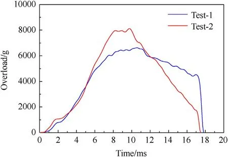
Fig.10.Comparison of the overload time histories of the two flight tests.
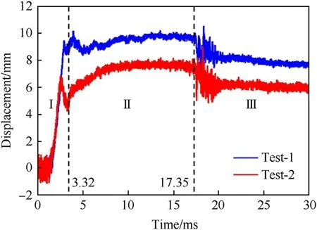
Fig.11.Comparison of the axial displacements recorded during the two flight tests.
The temporal histories of the overload values of the two gunlaunched tests are shown in Fig.10(a).The overload curves are relatively consistent in the ascending region.In addition, considerable differences can be seen in the middle region and descending region.The maximum overload value of the first flight test was 6633 g,while the maximum overload value of the second flight test was higher, at 8102 g.
3.1.2.Deformation of dummy propellant grains
Fig.11 shows the measured axial displacement-time curves along with the deformation processes of the dummy grain during the two fight tests.In general, the axial displacements of the two flight tests followed a similar variation trend.Moreover, the displacement of Test 2 was generally lower than that of Test 1.The displacement-time curves can be divided into three regions: I, a region of quick rise with an oscillation peak; II, a slowly rising region; and III, a region of strong fluctuations with continuously decreasing values.The first stage reflects a quick increase in displacement from 0 to 2.54 ms followed by a decrease from 2.54 to 3.32 ms.In the second stage,the displacement is maintained at an almost constant level from 3.32 to 17.35 ms.The third stage, representing the end of the overload duration, shows a decreasing trend after strong data fluctuations.The displacement of the grain in Test 2 was lower than that of Test 1 possibly due to the fact that the overload value of Test 2 is larger than that of Test 1,leading to a higher plastic deformation damage of grain in Test 2.
3.1.3.Contact stress
The measured contact stress-time curves of the two filght tests are shown in Fig.12.The figure shows that the contact stress variations exhibited almost the same trend as the overload values,i.e.,the contact stress increased during the first 8 ms and decreased from 11 to 20 ms.Moreover, the contact stress values of YL1 were higher than those of YL2.The contact stress at the bottom of the grain was much higher than that at other locations,indicating that the deformation of the dummy propellant grain occurred mainly at the bottom of the dummy propellant grain.
3.2.Simulation results
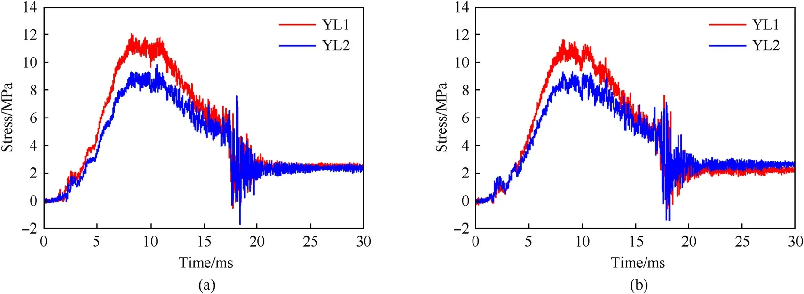
Fig.12.Contact stress-time curves of the two flight tests: (a) Test 1; (b) Test 2.
In this section, simulations of the mechanical response of propellant grain subjected to ultrahigh overload conditions were performed using the constitutive model developed in the present work.The overload values used in these simulations were obtained from the flight tests.The parameters in the constitutive model were derived from the data obtained in the uniaxial compression experiments.Then, a comparison between the simulation and flight test results was performed.
3.2.1.Constitutive model parameter derivation
Fig.13 shows the stress-stain curves of the dummy HTPB propellant obtained at strain rates ranging from 1.67 × 10⁻²to 2500 s-1.The mechanical properties of the dummy HTPB propellant were found to be strongly dependent on the strain rate.For all stress-strain curves obtained at different strain rates, the stress increased in a quasi-linear manner, especially when the strain exceeded 0.25.The yield behaviour of the dummy HTPB propellant was not obvious at all strain rates studied in the present work.
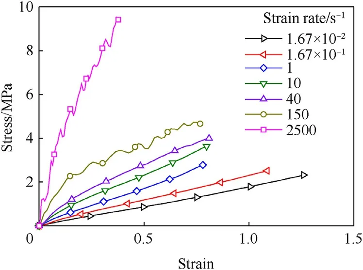
Fig.13.Stress-strain curves of wide-strain-rate compression.
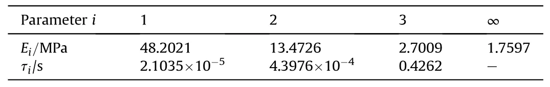
Table 8 Parameters of E(t).
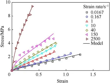
Fig.14.Stress-strain curves of the experimental and fitting data.
To establish a constitutive model for the analysed dummy HTPB propellant, the uniaxial compression stress-strain curves of the dummy HTPB propellant were fitted by Eq.(4).In the fitting process,we used a nonlinear least squares regression model to find the minimum objective function value.The objective function can be expressed as follows:
where m is the number of strain rates; n is the number of data points representing a single strain rate;x is an unknown parameter in the Prony series; σcis the fitting stress; and σeis the test stress corresponding to the current strain rate and strain.The Prony series obtained from these test data are shown in Table 8.Fig.14 shows a plot of the strain-stress variations predicted by the developed constitutive model and those obtained from the measurements.The results predicted by the developed constitutive model agreed well with the experimental results.
3.2.2.General description
As shown in Fig.15, eight points (A-H) located at the top and bottom of the dummy propellant grain were selected to study the deformation process of the dummy propellant grain.
The displacement-time curves of the points shown in Fig.15 are plotted in Figs.16 and 17.The figures illustrate that the deformation process of the dummy propellant grain can be divided into four regions: (I) The expansion region; (II) The region of inner-hole shrinkage; (III) The region of inner-hole filling and (IV) the recovery region.
The expansion region began when the grain overload exceeded 0 and ended when the grain contacted the case in the radial direction.In this range,the grain deformation mainly indicated axial compression and radial expansion.Along the axial direction, the grain was compressed,leading to a shortened inner diameter and a lengthened outer diameter of the dummy propellant grain.However, the grain did not contact the case in the radial direction.The radial and axial deformation distributions at t = 1.5 ms in the YZ plane are shown in Figs.18 and 19.
The region of shrinkage of the inner hole began when the grain contacted the grain case and ended when the inner hole at the bottom was filled with grain.In this region, the grain was continuously compressed in the axial direction, yielding to the contact between the grain and the motor case.As the grain was constrained by the grain case along the radial direction, shrinkage occurred in the inner hole of the grain.The radial and axial deformation distributions at 3 ms in the YZ plane are shown in Figs.17 and 18.The maximum shrinkage of the inner hole at the bottom of the grain was 5.28 mm.
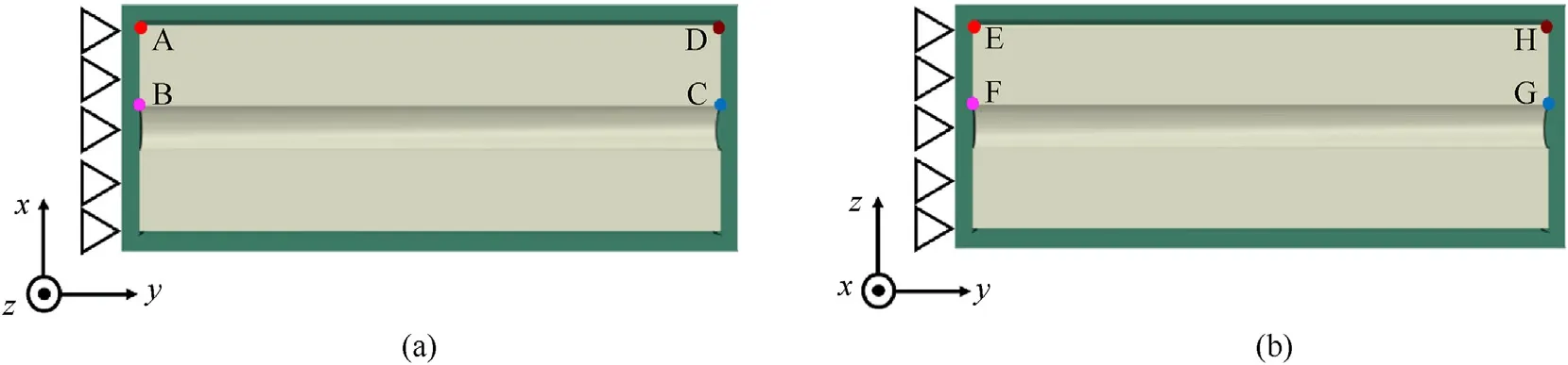
Fig.15.Location of the monitoring points on the propellant grain.
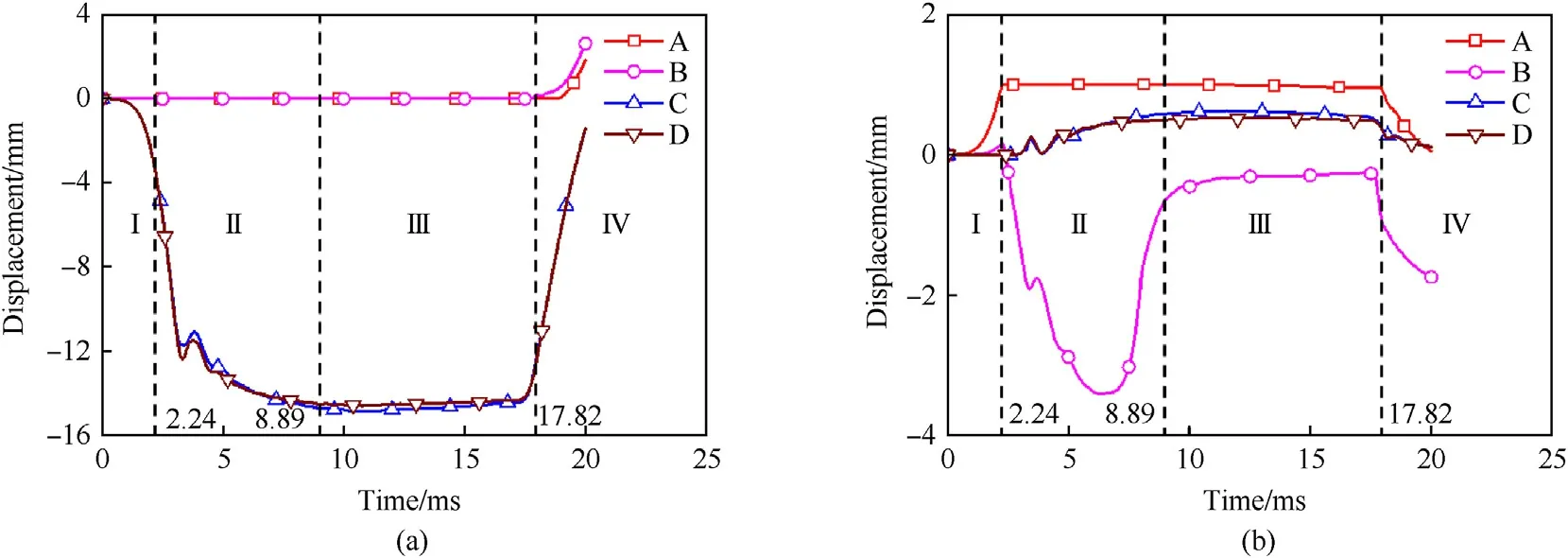
Fig.16.Displacement-time curves obtained at four locations on the grain in the XY-plane: (a) Axial displacement; (b) Radial displacement.
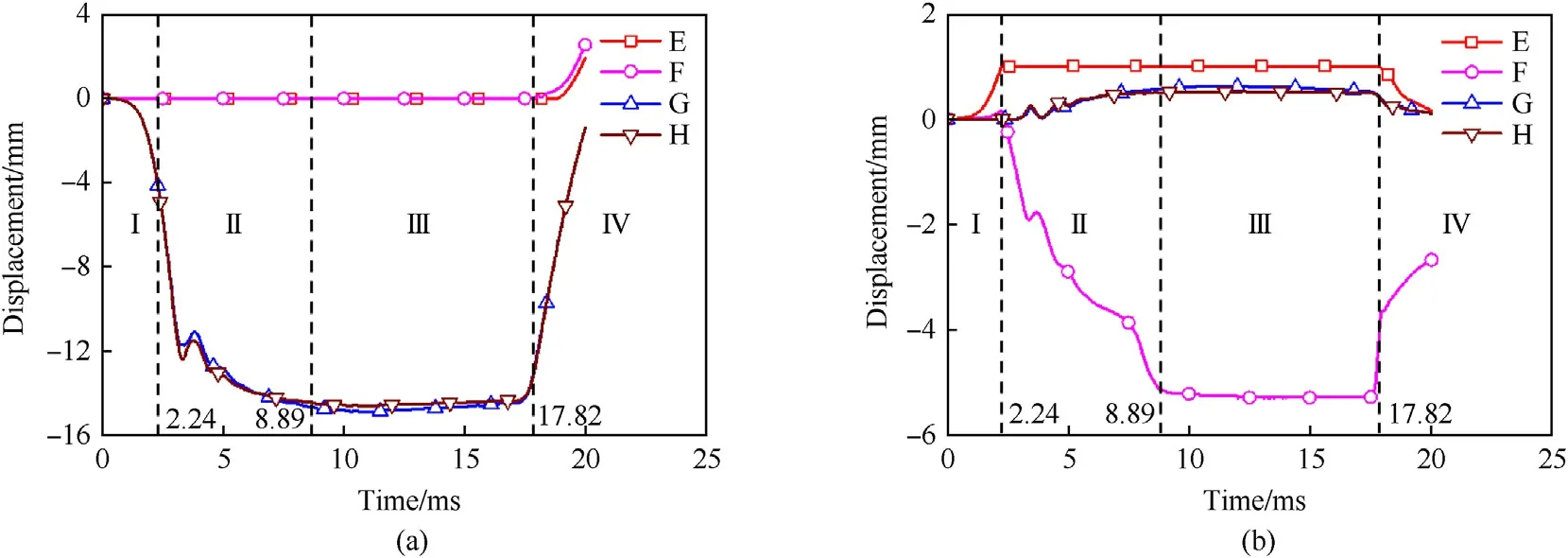
Fig.17.Displacement-time curves obtained at four locations on the grain in the YZ-plane: (a) Axial displacement; (b) Radial displacement.
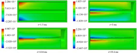
Fig.18.Radial deformation distribution variations on the grain.
The region of the inner-hole filling stage began when the radial displacement values of B and F were constant and ended when the overload value was 0.In this region,the axial-direction deformation of the grain was maximized.The radial and axial deformation distribution variations of the grain at time 12.8 ms in the YZ plane are shown in Figs.18 and 19.At this time,the inner hole at the bottom of the grain was partially filled with the grain.
The recovery region began when the overload value was 0 and ended when the simulation calculation was over.In this region,the dummy propellant grain began to recover to its original condition.Due to the viscoelasticity of the dummy propellant grain, the kinetic energy generated by the recovery of the grain caused the bottom of the grain to separate from the grain case in the axial direction, thus leading to a lengthened inner diameter and a shortened outer diameter.The deformation of the grain at 19.4 ms is shown in Figs.18 and 19.
3.2.3.Comparison between simulations and experiments
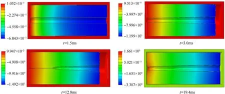
Fig.19.Axial deformation distribution variations of the grain.
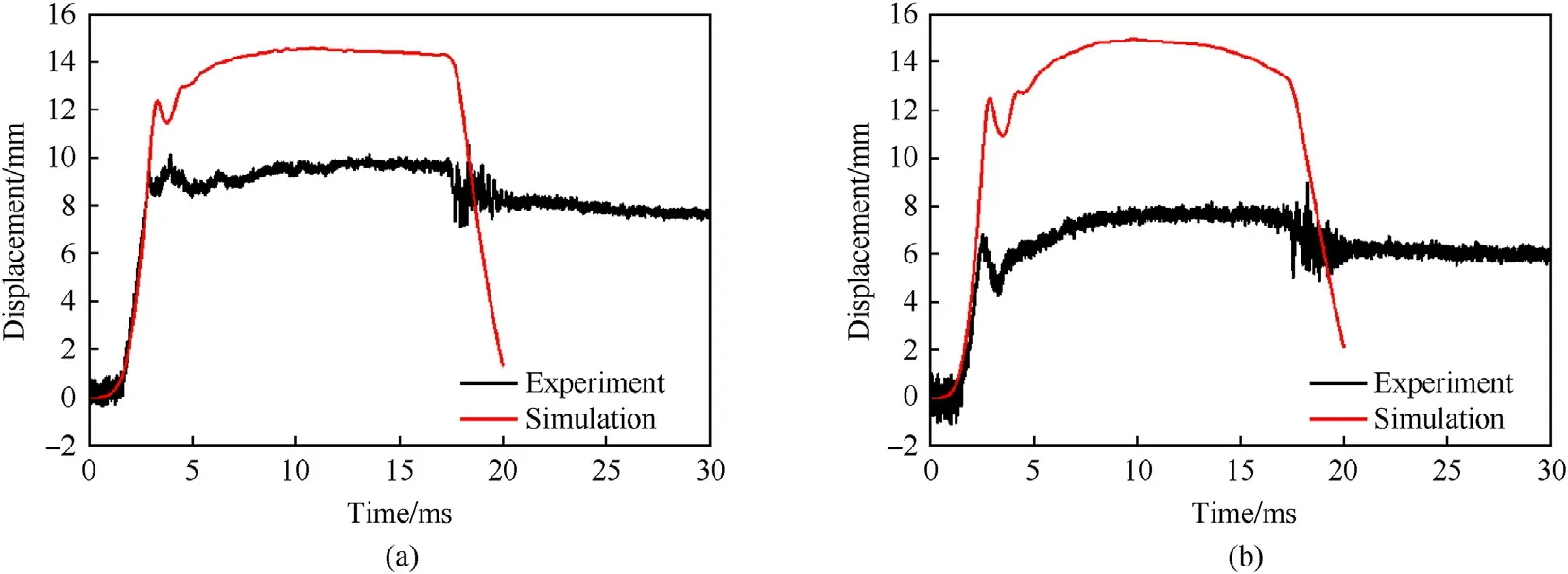
Fig.20.Axial displacement comparison between the simulations and experiments: (a) Test 1; (b) Test 2.
The results obtained when comparing the axial grain displacement between the simulations and the tests are shown in Fig.20.The displacement curves of the simulations and tests show a relatively consistent trend.Both curves show the characteristics of“rapid rise-oscillation peak-slow rise-platform”.However, the displacement in the simulations decreased rapidly when the overload decreased to 0, while the displacement in the test decreased slowly and then remained approximately constant.This is possibly caused by the effect of unrecoverable plastic damage which is not considered in our simulation.The displacement in the simulations was almost completely coincident with that in the tests in the ascending region; however, the maximum displacement values differed.The maximum axial displacement values were found to be 15.1 mm and 15.3 mm in the simulations, while the maximum axial displacement values measured in the experiments were 10.5 mm and 9.0 mm.The possible reason for these differences was the structure of the test projectile.When the axial displacement of the grain was maximized in the tests, the grain may have been struck at a certain position in the case.
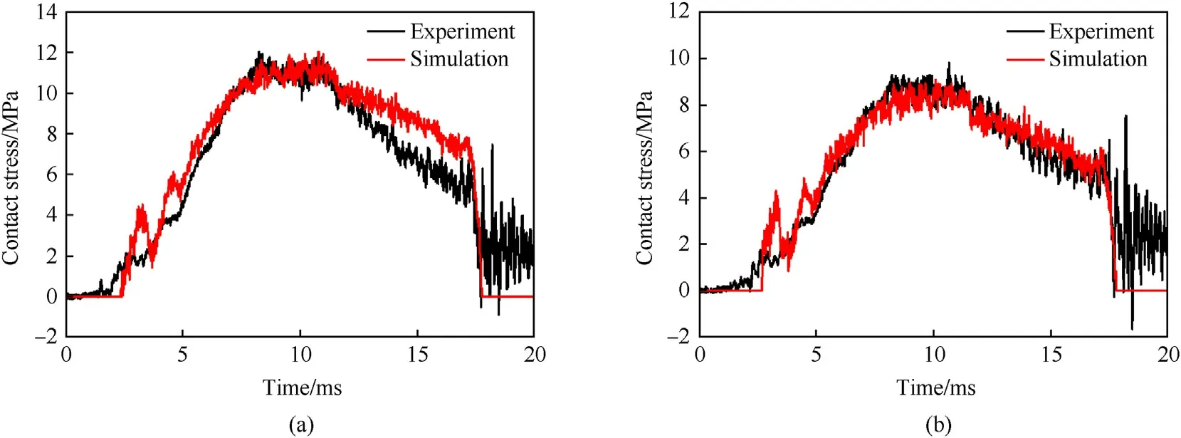
Fig.21.Contact stress comparison between the experiment and simulation of Test 1: (a) YL-1; (b) YL-2.
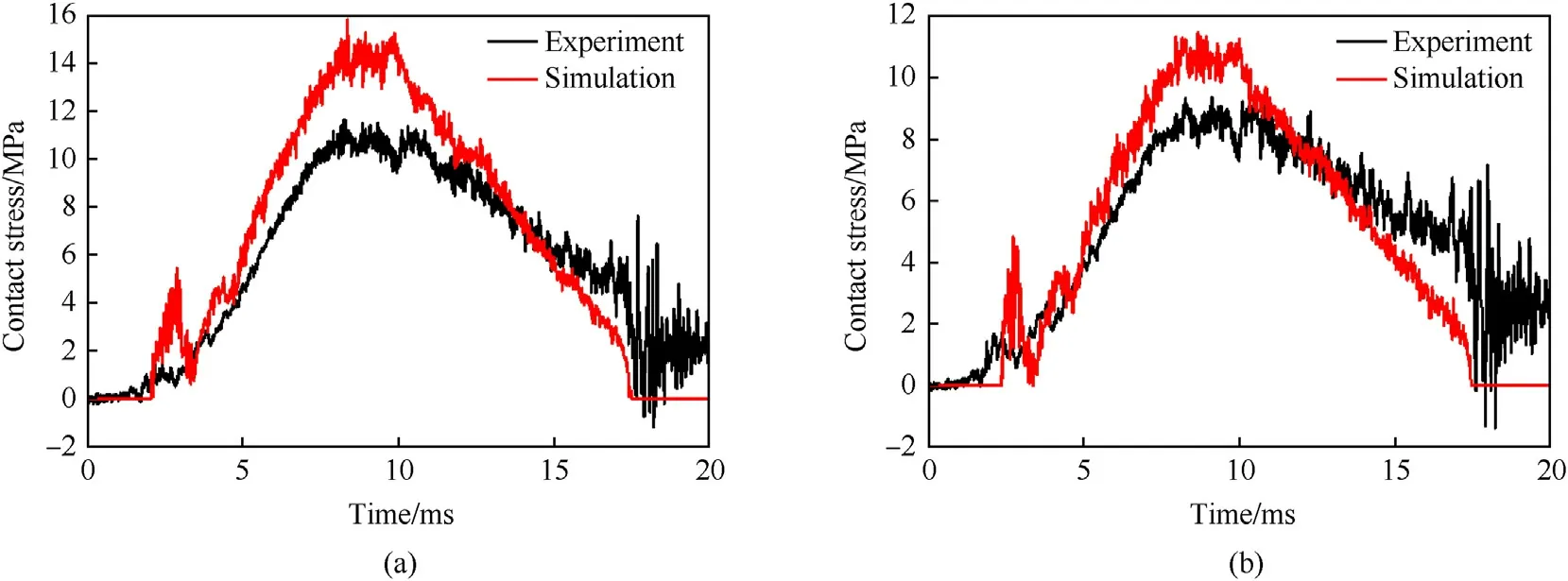
Fig.22.Contact stress comparisons between the experiment and simulation of Test 2: (a) YL-1; (b) YL-2.
Figs.21 and 22 show comparisons of the contact stress conditions between the simulations and tests.The simulation results obtained for Test 1 were consistent with the test results,indicating that within the measured time range,the results of Test 2 itself and the Test-2 simulation differed.In the ascending region of the simulation and test, the contact stress for Test 2 was consistent,while the maximum values of the contact stress differed.The difference between the simulation and experiments are possibly caused by the effect of friction between the grain bottom surface and the motor case.In simulation, the friction was neglected.However,in real conditions the friction between the grain and the bottom surface of the case limits the expansion of the grain in radial direction leading to less deformation of the fuel grain yielding to lower contact pressure.In conclusion, the simulation results can rightly reproduce the compression effect of the grain on the case under high overload conditions.
4.Conclusions
In the present work, we performed specifically designed gunlaunched flight experiments with onboard measurements to study the mechanical response of a dummy propellant grain subjected to ultrahigh overload conditions.Finite-element launchprocess simulations were also performed by using a viscoelastic constitutive model developed in the present work.The simulation and test results were then compared and discussed in detail.
The main conclusions are summarized as follows.
• A gun-launched missile flight test system was designed with reasonable accuracy.The contact stress between the grain and case,the axial displacement of the grain and the overload of the grain were successfully obtained from the onboard measurement system.
• The constitutive model developed in the present work could reasonably predict the mechanical response of the grain subjected to overload conditions.Compared with the test results,the calculated contact stress showed good agreement, though the displacement curves differed somewhat.
• The studied HTPB based inert grain could sustain overload values of 8102 g while maintaining structural integrity.During the launch process, the dummypropellant grain used in the present work exhibited large deformation due to the high acceleration conditions,which possibly led to friction between the motor case and dummypropellant grain.
Declaration of competing interest
The authors declare that they have no known competing financial interests or personal relationships that could have appeared to influence the work reported in this paper.

- Defence Technology的其它文章
- Ground threat prediction-based path planning of unmanned autonomous helicopter using hybrid enhanced artificial bee colony algorithm
- Layered metastructure containing freely-designed local resonators for wave attenuation
- Predicting impact strength of perforated targets using artificial neural networks trained on FEM-generated datasets
- Construct a 3D microsphere of HMX/B/Al/PTFE to obtain the high energy and combustion reactivity
- Ignition processes and characteristics of charring conductive polymers with a cavity geometry in precombustion chamber for applications in micro/nano satellite hybrid rocket motors
- Recent research in mechanical properties of geopolymer-based ultrahigh-performance concrete: A review