伦敦(2012奥林匹克城)排水隧道工程
2012-10-10 09:04MartinKnights
隧道建设(中英文) 2012年4期
Martin C.Knights
(Halcrows集团有限公司,伦敦)
0 引言
伦敦是一个被人口增长和气候变化所影响的国际化都市,这使得伦敦的交通网和排水网承受了较大的压力。为满足日益增长的交通需求,伦敦的地铁系统正在逐步升级,一条东西向的地铁线也在修建中。由于19世纪70年代修建的排水系统已经无法满足大暴雨和强降雨情况下的排水要求,为防止污水流入著名的泰晤士河,伦敦正在建设一个新的暴雨排污和储水隧道。
最近在上海举行的桥梁和隧道大会上,Knights先生介绍了伦敦最近当前最主要的隧道工程计划,阐述了一些值得关注的并已在这些工程中应用的技术创新。他的介绍是对刊登在会刊中的整个PPT的总结。
在本刊中,总结出该隧道工程的重点在于在伦敦强降雨时,如何防止泰晤士河被污染。
1 伦敦Tideway工程
见图1。
1.1 工程概况
1)由于伦敦的城市化进程,下水道和排水管网都无法满足暴雨时的排水需要。
2)Joseph Bazalgette先生是原(维多利亚时期)排水管网的设计师,他设计了一套污水处理系统,该系统由57个沿泰晤士河行潮段布置的合流下水道排水口(CSOs)组成。
3)设计此系统是为了防止建筑和街道被洪水淹没。
4)平水年,估计会排出3 900万m3的未处理污水,丰水年达平水年的3倍以上。
5)小到2 mm的降雨都会触发该系统排水。
6)由于人口的增长、城市化进程的推进以及气候的变化,糟糕的排水情况更是每况愈下。
7)在整个暴雨过程中,隧道都扮演着污水吸纳、运输和储存的角色。一般来说,污水会在48 h内被处理。因此,该工程实际上是污水处理厂(位于此隧道工程东端的Beckton)的扩展。
1.2 该工程的关键性挑战
1)地质情况复杂多变——黏土、混合地层、砂土、白垩系土层,而且地下水位高。
2)在恶劣污水环境下,设计寿命可达120 a。
3)采用涡轮式竖管消能,并尽量减少空气的夹杂。
4)采取实时控制来应对涌水。
5)为保持隧道环境清新并降低臭气释放到地面的风险,需进行机械通风和臭气处理。
6)液压方面的挑战:为减小滞留空气的影响,需要精细化管理,处理大量进入大型隧道的体积可变气流;在不影响现有系统正常运行的前提下,调节被动系统以实现适当的控制水平。
2 新工程
新工程分为2期。
2.1 一期隧道(Lee隧道)
一期工程正在建设中,见图2。施工期为3 a。
2.1.1 一期隧道必须现在就着手的原因
1)此隧道将解决伦敦污染最严重的合流下水道排水口问题。
2)目前,从Abbey Mills合流下水道排水口排出的污水占流入泰晤士河行潮段的未处理污水总量的40%。
3)此隧道平均每年要拦截1 600万t目前排入泰晤士河的未处理污水。
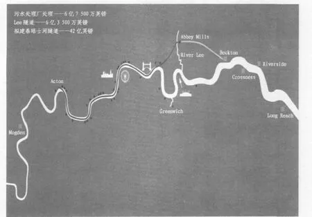
图1 伦敦Tideway工程
2.1.2 一期隧道的特征
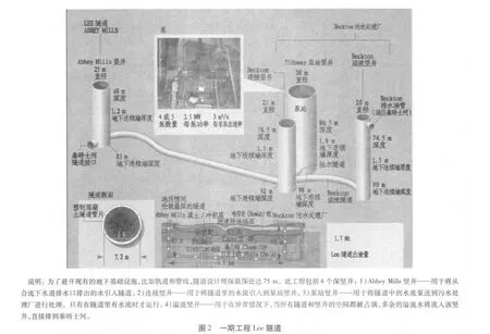
1)从Abbey Mills到Beckton污水处理厂,隧道全长 6.9 km。
2)隧道具有贮存和运输污水的功能。
3)隧道和竖井的总储存空间达到38.2万m3。
4)隧道埋深达75 m,内径7.2 m。
5)设置有4个最大直径为38 m的深竖井。
2.1.3 一期工程合同的内容
一期工程合同在2010年签订,内容如下。
1)该工程合同总额为6亿3 500万英镑——为英国水务史上数额最大的承包合同(此前,最大的项目合同额为4亿2 000万英镑)。
2)由 Morgan Sindall、万喜大型建筑工程公司(Vinci Construction Grands Projets)和法国地基建筑有限公司(Bachy Soletanche)共同组成英法项目联合体(MVB)。
3)施工高峰期需要500个员工(包括工人)。
4)是目标成本合同。
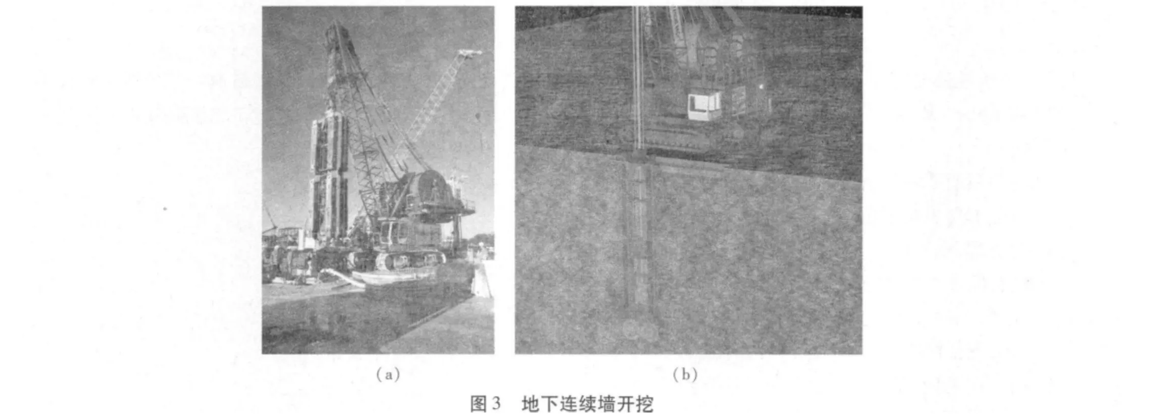
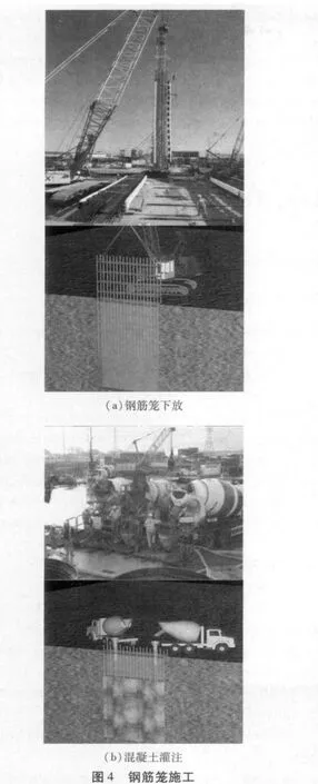
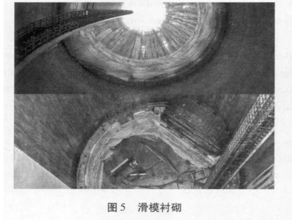
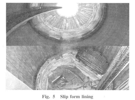
一期工程包括4个深竖井(见图2),用深达98 m的地下连续墙(见图3和图4)作为竖井的初期支护,用滑模衬砌(见图5)作为二次衬砌。该6.9 km长的隧道用土压平衡盾构(EPB)施工,用预制纤维混凝土管片作为二次衬砌。
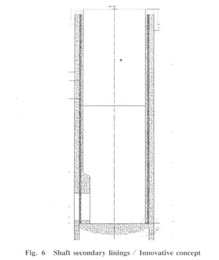
2.1.4 竖井二次衬砌的新理念
基于创新理念(见图6)进行竖井二次衬砌施工。
1)形似混凝土烟囱。
2)外圈为高流动性混凝土。
3)防止收缩裂缝。
4)防止张力上升。
5)防止将来弹性压缩。
6)设计用素混凝土。
7)可实现滑模施工。
8)用钢纤维来增强耐久性。
9)建造每个竖井大约节约700 t钢筋。
2.2 二期工程(伦敦泰晤士河Tideway隧道)
2.2.1 二期工程的主要特征
二期工程的主要特征见图1。
1)规模:20 km,直径 7.2 m;5 km,直径 6 m;4 km,直径5 m。
2)深度:起点深度大约30 m,终点Abbey Mills泵站深度为67 m。每790 m隧道埋深降低1 m,因此隧道可以实现自清洗。
3)宽度:内径为7.2 m。
4)容量:48 h内,可贮存150万m3(包括Lee隧道)。
5)线路:主要沿着泰晤士河。
6)合流下水道排水口控制:21个出口通往隧道;可控制13条水流。
7)通过Lee隧道和泰晤士河Tideway隧道,保证英国能够遵守欧盟城市污水处理指令。
2.2.2 二期隧道建设的分包模式和范围
3个地理分包区域与主隧道掘进方向在一条线上(西部、中部和东部)。分包区域覆盖了掘进竖井、拦截竖井和联络通道。合同将尽量减少承包商之间的接口。
主要工程合同包括:
1)3个按地理位置和地质情况划分的隧道和竖井合同。
2)污水处理厂需承担复合接口,包括现有排水道的处理工作;其他由隧道和竖井的承包商来负责处理。
3)由方案设计得出的设计/建筑合同。
4)在其分包的地理范围内,承包商全面负责项目的各个方面。包括:①由方案设计和最低标准规范得出的设计/建筑方案;②TBM的设计和采购及隧道衬砌和竖井的施工;③所有材料及渣土的河流、公路及铁路运输。
2.2.3 二期工程建设计划
1)设计:2015年完成。
2)土地收购:掘进地段2013年;所有其他地段2015或2016年。
3)二期工程招投标(ITT-Q2):2013年。
4)发包:2015年。
5)现场开工:2016年。
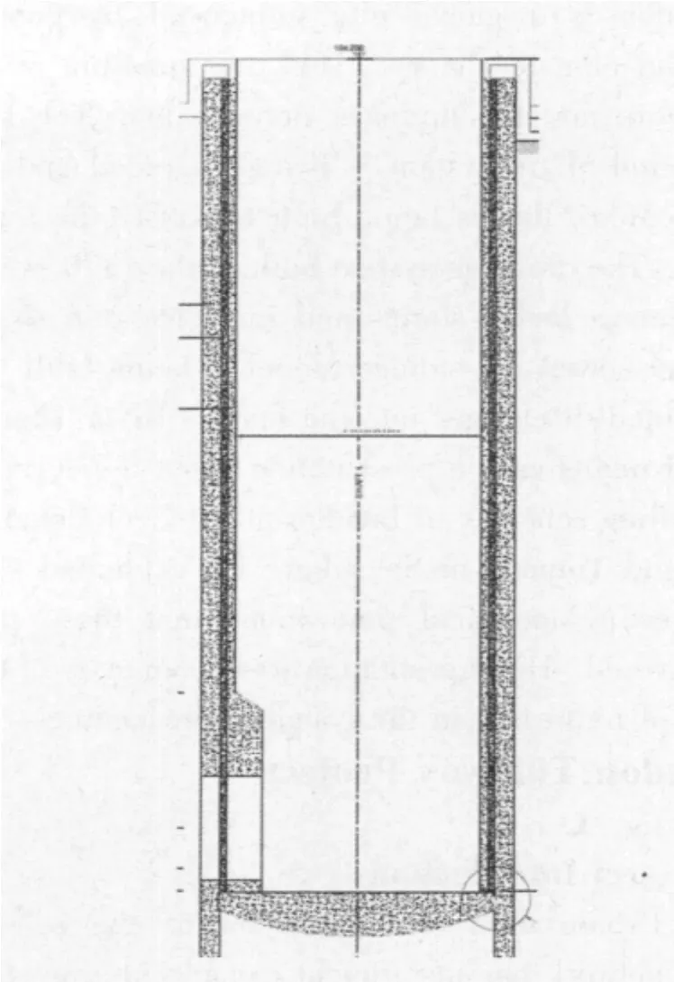
图6 竖井二次衬砌新理念
3 说明
作为业主,泰晤士水务公司(Thameswater)正在全球寻求感兴趣的承包商。许多欧洲建筑公司表示出了兴趣。对于在施工难度与伦敦Tideway隧道工程类似的复杂软弱地层条件下的重大城市隧道工程方面有经验的亚洲承包商/供应商,业主很有兴趣与他们合作并期望他们对本项目感兴趣。
如对本项目感兴趣,请联系泰晤士水务公司的Keith Farley(Keith.Farley@tidewaytunnels.co.uk),以获取更多的信息。
(本文由《隧道建设》编辑部译,英文原文由Martin C.Knights供稿,见本期第608—612页)
Editor’s comment:The heavy rain on July 21,2012 has led to great damage to Beijing.The major cause for the disaster might be the water drainage system.Flood often occurs in cities in China in resent years.Martin C.Knights,former president of International Tunneling Association,is asked to give a presentation on underground drainage systems in London,including drainage systems constructed in Victorian period,drainage systems under construction and drainage systems to be constructed,so as to provide reference for city construction in China.Meanwhile,Martin C.Knights said that the owner,Thameswater,is seeking international interest from Contractors,and is interested to learn about Contractor/Supplier from Asian counties who have experience in major urban tunnel projects in complex soft ground conditions,where the construction challenges have been similar to those in London Tideway Tunnel Project.
Correrponding author:Martin C.Knights,International Tunneling Asoociation 2007—2010,Halcrows Global Tunnel and Geotechnical Practice Leader,has hearly 40 years erperience in the Eiril engineering indaitny pati calonly with anderground projects in urban and sabaqueous eavironmenes.He has worked on tunnel,hydro,transport and water projects in the U.K.,USA,South Africa,Switzerland,and Saudia Arabia.He has recently undertaken peer reciew for Engineering and Tunnelling aspects of the Thameswater London Tideway Tunnels Project.He is the expert panel member for tunnels/shafts/stations for London Crossrial project for Government and City Transport Sponsor.
0 Introduction
London is a global city influenced by population growth and climate change.This puts pressure on transport network and the drainage network too.The London Underground Metro system is being upgraded and a new west-east Metro line is being built to satisfy the transport demand.The drainage system built in the 1870’s is unable to manage heavy storms and intensive rain so a new stormwater sewer and storage tunnel is being built to prevent polluted discharges into the famous River Thames.
Mr Knights gave a presentation about the current major tunnelling schemes in London at a recent Congress on Bridges and Tunnels in Shanghai.He explained some of the interesting technical innovations that these projects have delivered.His presentation was a summary of the extensive ppt published in the congress proceedings.
1 London Tideway Project
See fig.1.
1.1 Project Introduction
1)Urbanisation of London means the sewer and drainage network has insufficient capacity during storm events.
2)The original network designer was Sir Joseph Bazalgette who planned a sewerage system was constructed with 57 Combined Sewer Outfalls(CSOs)along the tidal River Thames.
3)It was designed to prevent flooding to buildings and streets.
4)In an average year,39 million cubic metres of untreated sewage is estimated to be discharged;up to three times more in wet years.
5)As little as 2 mm of rainfall can trigger a discharge.
6)It’s a bad situation getting worse,due to population growth,increased urbanisation and climate change.
7)Tunnel operates as collector,transporter and storer of sewage until storm has passed.Generally treated within 48 hours.Effectively therefore an extension of the sewage works(at Beckton at the east end of the tunnel project).
1.2 The key challenges of the project
The key challenges are as follows:
1)Variable ground conditions- Clay,mixed ground,Sands and Chalk and a high water table.
2)To provide a 120 year design life for an aggressive sewage environment.
3)Dissipate energy and minimise air entrainment by use of a vortex drop pipe.
4)Implement real time control to deal with hydraulic surges.
5)Provide mechanical ventilation and odour treatment to keep tunnel environment fresh and reduce risk of odorous air release at ground level.
6)Hydraulic challenge,including:Dealing with a large number of variable volume flows into a large tunnel has required careful management to reduce the impacts of air entrapment;Adapting a passive system to enable the appropriate levels of control without disrupting the operation of the legacy system.
2 New Project
The new project is in two phases and phase1 is underway see fig.2 .Construction will take 3 years.
2.1 Phase 1 Tunnel(The Lee Tunnel)
2.1.1 Reasons for this phase of tunnelling has to be undertaken now
1)The tunnel resolves the single worst polluting CSO in London.
2)Abbey Mills CSO is responsible 40%of the total volume of untreated sewage currently entering the tidal River Thames.
3)It will intercept 16 million tonnes of untreated sewage currently discharged into the River Thames each year on average,via the River Lee.
2.1.2 Features that phase 1 consists of
1)A 6.9 km long tunnel from Abbey Mills to Beckton STW.
2)Storage and transfer tunnel.
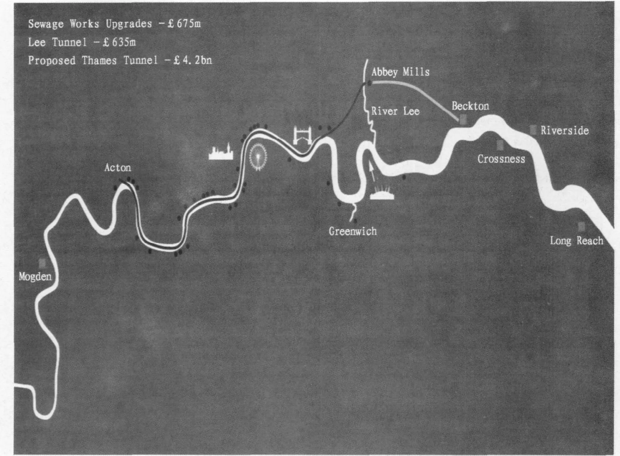
Fig.1 London Tideway Project
3)Entire storage space of 382 000 m3provided by both the tunnel and shafts.
4)Up to 75 m underground with an internal diameter of 7.2 m.
5)4 no deep shafts up to 38 m in diameter.2.1.3 Contents of Phase 1 Contract
The Phase 1 Contract was let in 2010 as follows:
1)635 million project-largest contract the UK water industry has ever awarded(£ 420 million).
2)French UK Joint venture comprising Morgan Sindall,Vinci Construction Grands Projets and Bachy Soletanche(MVB).
3)500 staff(including labour)at peak construction.
4)Target Cost Contract.
The Phase 1 project has 4 deep shafts(see fig.2)and are constructed using a primary shaft lining of diaphragm walls up to 98 m deep(see fig.3 and fig.4)and then a slip form lining as a secondary lining(see fig.5).The 6.9 km long tunnel will be built using an EPBM and precast concrete fibre reinforced lining segments with a secondary protection lining…
2.1.4 An innovative concept of shaft secondary lining
The Shaft Secondary Lining of the shafts used an innovative concept(see fig.6)as follows:
1)Formed as a concrete chimney.
2)External annulus of high flow concrete.
3)Avoids shrinkage cracking.
4)Avoids tension development.
5)Avoids future elastic shortening.
6)Design as plain concrete.
7)Slipforming possible.
8)Steel fibres to increase durability.
9)Saved approx.700 tonnes rebar per shaft.
2.2 Phase 2(London Tideway Tunnels)
2.2.1 Key featares of Phase 2
The key features of phase 2(London Thames Tideway Tunnel)are - -:see fig.1:
1)Size:20 km,7.2m diameter;5 km,6m diameter;4 km,5m diameter.
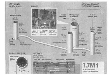
Fig.2 Phase 1 Tunnel(The Lee Tunnel)
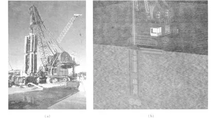
Fig.3 Excavation of diaphragm walls
2)Depth:Starts at around 30 metres,it will finish at 67 metres deep at Abbey.Mills Pumping Station.Falls one metre every 790 metres so it can be self-cleansing.
3)Width:7.2 metres internal diameter.
4)Capacity:1.5 million cubic metres(including Lee Tunnel)giving 48 hours storage.
5)Route:primarily follows the River Thames.
6)CSO control:21 connections to tunnel;13 flow controlled.
7)The Lee and ThamesTideway Tunnels will ensure that the UK can comply with the European Union’s Urban Waste Water Treatment Directive.
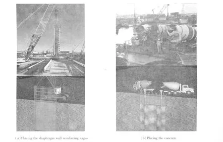
Fig.4 Diaphragm wall construction
2.2.2 Phase 2 Tunnel construction packaging strategy and scope
Three geographic delivery areas are aligned to main tunnel drives,western,central and eastern.Delivery areas will include drive shafts,interception shafts and connecting tunnels.Contracts will minimise interfaces between contractors.
The scope of the main works contracts will include:
1)3 tunnel&shafts contracts separated by geography and geology.
2)Complex interface with existing sewers to be undertaken by TW;all others by the tunnels&shafts contractors.
3)D & B contracts from scheme design.
4)Contractors fully responsible for all aspects of project within their geography.Including:① Design&build from a scheme design and minimum standards specification.② Design and procurement of the TBMs,tunnel linings,shaft construction.③ All logistics including river/road/rail transport of materials and excavated construction material.
2.2.3 Construction Programme for Phase 2
1)Planning process-complete 2015.
2)Land procurement-drive sites 2013.All other land 2015/16.
3)ITT-Q2 2013.
4)Contract award-2015.
5)Commence on site 2016.
3 Note
The owner,Thameswater,is seeking international interest from Contractors.Many European construction companies have expressed interest.The owner is interested to learn about Contractor/Supplier interest from Asian counties who have experience of major urban tunnel projects in complex soft ground conditions where the construction challenges have been similar to the London Tideway Tunnels Project.
For those interested in more information contact Keith Farley of Thameswater[Keith.Farley@tidewaytunnels.co.uk].
猜你喜欢
内江科技(2022年11期)2022-12-19
英语文摘(2022年7期)2022-07-23
看世界(2019年24期)2019-11-28
环球时报(2019-11-11)2019-11-11
中国水运(2019年7期)2019-09-27
科学Fans(2019年6期)2019-07-26
大科技·百科新说(2018年10期)2018-01-15
中学生博览(2016年10期)2016-09-10
现代营销·经营版(2016年1期)2016-05-14
乐活老年(2016年12期)2016-04-14