
Quantitative analysis of the performance of vector tracking algorithms①
2017-09-25 13:01WangQianCuiXiaoweiLiuJingZhaoSihao
High Technology Letters 2017年3期
Wang Qian (王 前), Cui Xiaowei, Liu Jing, Zhao Sihao
(*Beijing Satellite Navigation Center, Beijing 100094, P.R.China)(**Department of Electronic Engineering, Tsinghua University, Beijing 100084, P.R.China)
Quantitative analysis of the performance of vector tracking algorithms①
Wang Qian (王 前)②*, Cui Xiaowei**, Liu Jing**, Zhao Sihao**
(*Beijing Satellite Navigation Center, Beijing 100094, P.R.China)(**Department of Electronic Engineering, Tsinghua University, Beijing 100084, P.R.China)
Vector tracking changes the classical structure of receivers. Combining signal tracking and navigation solution, vector tracking can realize powerful processing capabilities by the fusion technique of receiving channel and feedback correction. In this paper, we try to break through the complicated details of numerical analysis, consider the overall influencing factors of the residual in observed data, and use the intrinsic link between a conventional receiver and a vector receiver. A simple method for performance analysis of the vector tracking algorithm is proposed. Kalman filter has the same steady performance with the classic digital lock loop through the analysis of the relation between gain and band width. The theoretical analysis by the least squares model shows that the reduction of range error is the basis for the superior performance realized by vector tracking. Thus, the bounds of its performance enhancement under weak signal and highly dynamic conditions can be deduced. Simulation results verify the effectiveness of the analysis presented here.
vector tracking, dynamic stress noise, loop band width, pseudo-range error
0 Introduction
Satellite navigation systems can provide precise real-time positioning, velocity measurements, and timing services in all weather conditions and at any location. With continuous expansion and improvement of human production and living standards, the requirements of satellite navigation terminals have increased. Traditional receiving terminals cannot perform optimally in highly dynamic and weak signal conditions, which is a major limit on satellite navigation applications. A series of solutions for improving satellite navigation terminal performance have appeared, including inertial navigation assistance, satellite power boosting, and vector tracking.
Among all of the aforementioned solutions, only “vector tracking” focuses on improving receiver performance without the help of an auxiliary external system, which has made vector tracking an active and growing area of research. The basic idea of vector tracking[1]is to combine channel tracking and navigational information from all of the received channels using an extended Kalman filter. The position results are obtained while simultaneously using measured values as a feedback signal for the local oscillator in order to maintain stable satellite signal tracking.
Compared with a traditional scalar-loop structure, a vector-loop receiver can indeed exhibit superior performance. In particular, a vector-loop receiver can achieve stable tracking under highly dynamic and weak signal conditions. The advantage of vector-loop channel fusion effectively reduces the measurement error, thereby enhancing the carrier-to-noise ratio and sensitivity of the receiver. In dynamic environments, vector tracking algorithms can use vector decomposition to track dynamic signals in the correct direction by using characteristics of the motion to offset the dynamic stress in a strong dynamic direction, and reduce ineffective setting in a weak dynamic direction.
Many publications have presented detailed analyses that quantify the advantages of vector loop performance. Refs[2] and [3] presented comparative analyses of vector and scalar loop receiver performance under different scenarios. Ref.[3] emphasized the superiority of vector loops under the condition of losing and recapturing lock. Ref.[4] described the tracking performance exhibited by a vector loop under the condition of ionospheric scintillation. Ref.[5] compared and analyzed the tracking performance of scalar and vector loops based on Kalman filtering under the condition of lower signal to noise ratio. All of the aforementioned documents emphasize the tracking advantages of vector loops in various harsh environments, however, systematic and in-depth analyses of the performance of vector tracking algorithms are limited.

Based on the aforementioned research work, this article focuses on the physical factors that influence vector tracking algorithm performance, and points out the role of the Kalman filter in the algorithm. Starting from a bandwidth analysis, an in-depth discussion on how vector tracking achieves excellent performance with highly dynamic and weak signals is presented. A theoretical analysis that quantifies the enhancement range of vector tracing performance for engineering applications is proposed and verified by simulation.
1 Model description
1.1 Signal model
The downlink signal in satellite navigation system is modulated by pseudo code and carrier wave. The signal is input to the base band after frequency conversion through RF module, which can be expressed by

(1)
where, t is the receiving moment, N is the number of visible satellites, and ai, τi, φiand fd,iare the amplitude, the phase delay, the carrier phase, and the Doppler frequency shift of signal i, respectively. Si(t-τi) is the modulation spreading code for the corresponding signal, and n(t) is white Gaussian noise. The process of tracking in the receiver is used to obtain the aforementioned signal parameters from the noise signal. A scalar loop obtains the parameters of a single branch through an independent DLL (delay locked loop) /FLL (frequency locked loop) minor feedback loop, while a vector loop obtains the parameters of all of the branches simultaneously through a VDLL/VFLL major feedback loop.
1.2 Vector loop structure model
The model of a vector loop is shown in Fig.1, and the core is based on discrete time state recursion. In the initial stage of system operation, estimates of the necessary signal parameter information of position and velocity are obtained via a scalar loop as mentioned in Section 1.1. After this initial operation, the scalar loop connection between the discriminator and the local reference oscillator should be disconnected. The discriminator outputs the predicted error vector of the observed value and, by processing this data with a Kalman filter, the vectors of displacement and velocity can

Fig.1 The model of a vector loop
be updated. After radial projection in the direction of the satellite, the predicted code phase/frequency and carrier frequency can be obtained in order to drive the local reference oscillator to recover the pseudo code and carrier information. Thus, a complete signal vector tracking process is realized.
During continuous operation of the vector loop, updates of the Kalman gain are mainly based on the following recursion formula:
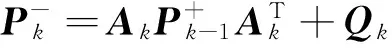

(2)

1.3 Influence factor analysis
As shown in Fig.1, the Kalman filter is the core of the vector loop, and its parameters directly influence the performance of the vector tracking algorithm. The state variables of the filter are signal synchronization parameters such as power, code phase and carrier Doppler. In the corresponding mode the measure variables are the surplus estimations of the above parameters derived from the descriminators. In general, Kalman filtering consists of two processing procedures: “prediction” and “correction”, where the state noise and measurement noise should be used, respectively. The covariance matrix of the state noise is composed of signal power noise and carrier Doppler noise. Note that carrier Doppler noise depends on the state of satellite motion, receiver motion, and the clock drift of user’s equipment. The covariance matrix of measurement noise consists of the residual code phase delay, the residual Doppler shift, and the discriminator error variance for the residual signal power. The discriminator commonly adopts the non-coherent power method, for which the expression of discriminator error variance[9]is
(3)
(4)
(5)

2 Theoretical analysis
2.1 Thermal noise analysis

(6)

(7)

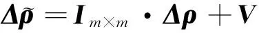
According to the principle of the vector loop, the displacement vector can be transformed into a pseudo range variation only by radial projection in the direction of the carrier and satellite.
(8)
Similarly, according to the least square method, equation
(9)
can be solved as:

(10)
The estimated variation of a pseudo range can then be expressed as
(11)
And the error variance of vector loop equals to:
(12)

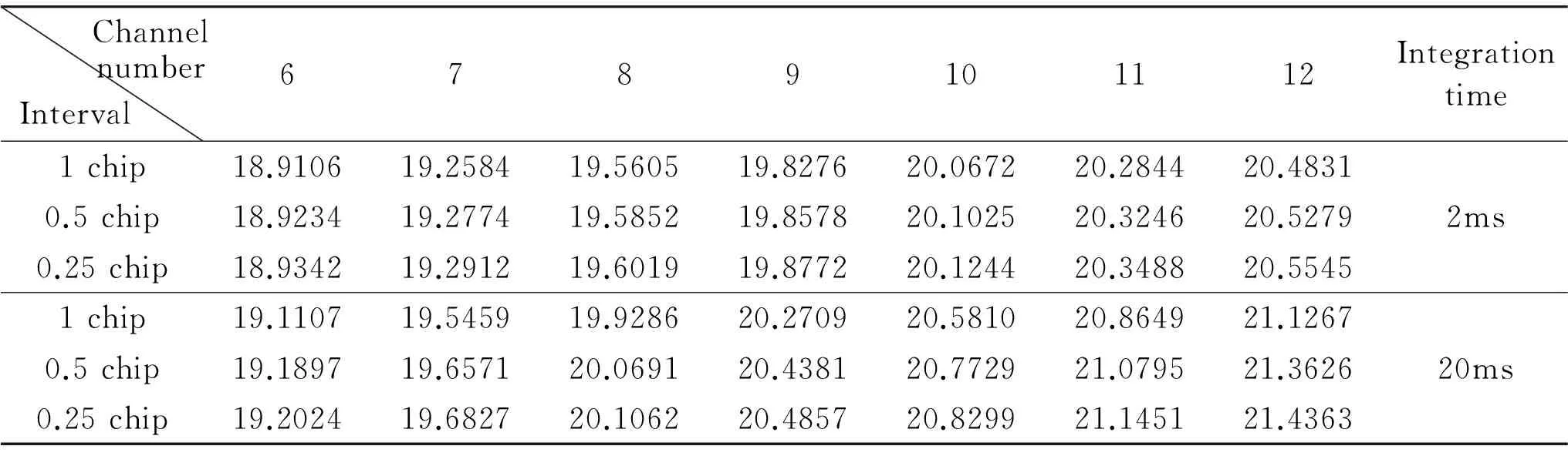
Table 1 The processing performance of weak signals by the vector loop
2.2 Dynamic stress analysis
(13)
The classical expression of dynamic stress error is shown in Eq.(13), where α is the loop bandwidth, B is the empirical coefficient of characteristic frequency conversion, R is the distance between the carrier and the satellite, and n is the loop order. The value of the dynamic stress is mainly related to two factors: 1) the relative dynamic state between the carrier and the satellite, and 2) the characteristic frequency, which is closely related to the loop bandwidth. Because the dynamic stress error generated in the transient response is much larger than that in the steady state response, the loop bandwidth is generally conservative in order to guarantee the signal frequency and phase change caused by the dynamic motion of the loop are rejected.
In Section 2.1, it shows that a vector loop improves the noise performance of the loop, which reduces the requirement of a conservative loop bandwidth. Therefore, the bandwidth can be increased to increase signal tracking performance in the presence of dynamic stress.
Under the premise of the same noise variance, the loop bandwidth of a vector loop can be increased to improve adaptability to the dynamic stress error experienced by the receiving terminals. Fig.2 shows that the tolerance of the loop bandwidth increases gradually as the carrier to noise ratio increases. Moreover, if the coherent integration time is longer, this advantage is more obvious. When the carrier to noise ratio increases from 18dB·Hz to 20.5dB·Hz, the bandwidth of the 2ms integral increases from 2Hz to 4.5Hz, and the bandwidth of the 20ms integral increases from 2Hz to 6Hz. However, the ability to increase the integration time is always limited by factors such as the message data, dynamic stress, frequency stability of the crystal oscillator in the receiver, etc. Thus, it is not suitable to set the integration time too long. Note that the input of the vector loop still employs the frequency discriminator output of a traditional scalar loop, therefore, the threshold value of the frequency tracking loop can be expressed by

(14)

Fig.2 The bandwidth variation under weak signal conditions
In Eq. (14), σwis the root mean square of the frequency error caused by thermal noise, and θeis the tracking error caused by the dynamic stress. Under weak signal conditions σwis very large, so the margin for dynamic stress is very small, and the effect of the increase in dynamic range is not obvious.
When the carrier to noise ratio is relatively high, the curve in Fig.3 indicates that the effect of the integration time on performance can be neglected. To summarize, according to Eq. (13) with all other parameters being equal, doubling the bandwidth in a first order loop increases the tolerable dynamic stress by a factor of 2, and doubling the bandwidth in a second order loop increases the tolerable dynamic stress by a factor of 4.
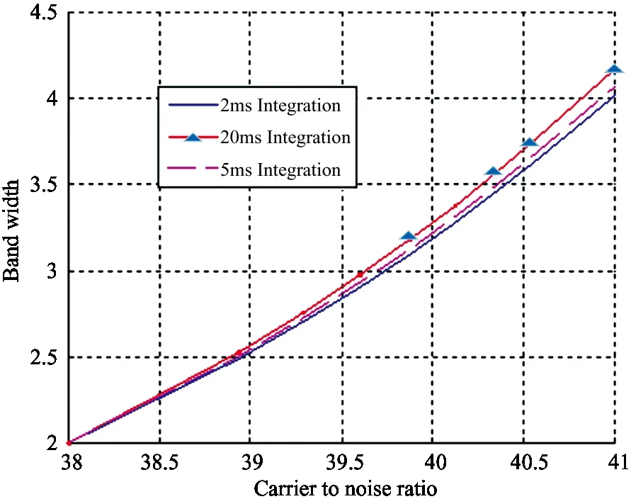
Fig.3 The bandwidth variation under strong signal conditions
3 Performance Verification
3.1 Simulation environment
In the simulation results presented here, a signal generator produces the multi-channel BPSK navigation signal. The signal intensity in each channel is constant, and C/N0is set to 19dB·Hz for a weak signal, and 40dB·Hz for a normal signal. The Nyquist sampling rate is 8.184MHz, and the simulation duration is 400s. The simulated movement is a combination of uniform acceleration and sudden acceleration. The acceleration jumps from 0.5g m/s2to -0.5gm/s2, where the high one is from 6g m/s2to -6g m/s2. Signal setting of simulation is consistent with the presented tracking threshold of VDFLL[10].
The two receivers implemented here use a scalar receiver and a vector VDFLL receiver, respectively. For a fair comparison between the two types of algorithms, both are based on the tracking loop of a Kalman filter and the influence of a changing loop bandwidth on the algorithm performance is neglected. Observation noise parameters are captured directly from the output value of the discriminator, and process noise parameters are fixed under weak signal conditions without the adaptability adjustment that could be obtained from the variation of the dynamic state of the carrier. Although this parameter adjustment is useful for improving the performance, it prevents comparing the two algorithms on the same platform. Under highly dynamic conditions, the bandwidth parameter is adjusted according to the dynamic state while maintaining the same measurement error is desired. The loop integral time is set to 20ms in all cases.
3.2 Weak signal processing analysis
Fig.4 and Fig.5 list the code phase delay error, carrier frequency error due to Doppler shifts for different numbers of satellites (6, 8, and 11), respectively under weak signal conditions (19dB·Hz, ±0.5g m/s2). These conditions provide insight into the processing capability of the VDFLL architecture in a weak signal environment. Fig.4 and Fig.5 reveal that with an increasing number of satellites, the code phase error and carrier frequency error are both reduced. When the number of satellites is 6, FLL and DLL are out of lock, so the error is large. Scalar receivers with same settings can achieve a stable tracking state for the signal parameters of (23dB·Hz, ±0.5g), which is in line with the theoretical analysis presented in Section 2.
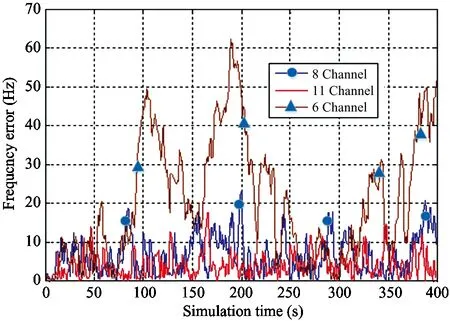
Fig.4 Frequency error under weak signal conditions

Fig.5 Code phase error under weak signal conditions
3.3 Dynamic stress processing analysis
Fig.6 and Fig.7 list the code phase delay error, carrier frequency error due to Doppler shifts, and position error for different numbers of satellites (6, 8, and 11), respectively, under highly dynamic conditions (40dB·Hz, ±6g m/s2) in order to investigate the processing capability of the VDFLL architecture in a highly dynamic environment. Due to different simulation parameters, the results are not entirely consistent with those obtained in the weak signal environment. Owing to the excellent signal quality, the errors of code phase with different satellite number are not obvious. From Fig.7, it should be pointed out that the frequency error of channel 6 is between 8 and 12Hz,

Fig.6 Code phase error in highly dynamic conditions

Fig.7 Frequency error in highly dynamic conditions
which is close to the threshold value of the FLL’s tracking bandwidth (12.5Hz). Therefore, it is the loss of lock in the FLL that causes the final positioning failure. In addition to the bandwidth parameters, the other scalar receivers with the same parameter settings reach a stable tracking state for the signal parameters of (40dB·Hz, ±3g m/s2), which is in good agreement with the theoretical analysis presented in Section 2.
3.4 Validation with actual data
In order to validate the performance, an actual real-time data is used by RF signal recording and playback apparatus[11]. The trajectory of the vehicle on the highway with the velocity of 90km/h is shown as Fig.8. The C/N0of GPS collected satellite signal is 44dB·Hz.

Fig.8 Trajectory of the vehicle on the highway
In this condition, the measure errors of VDLL and VFLL with the vector loop are 0.0021 chip and 0.45Hz, while those with the scalar loop are 0.0032 chip and 3.8Hz. This experiment shows the advantage of VDLL/VFLL in signal tracking compared with DLL/FLL in the regular scene.
4 Conclusion
The vector tracking architecture in global navigation satellite system (GNSS) receivers has the advantage of increased performance through multi-channel integration processing, but it also has disadvantages including a complex structure and the need to perform a large number of calculations. Thus, analyzing its performance is also a problem in industry settings. In this paper, transformation between vector tracking and scalar tracking is used to determine the influence and constraints of integration time, loop bandwidth, thermal noise, dynamic stress, and other factors that affect receiver performance. The vector loop can reduce the observation error and improve performance through accurate feedback obtained by multi-channel fusion technology. Under equivalent conditions, the vector receiver exhibits a gain that is 3dB higher, or endures 2~4 times the dynamic stress, when compared with a scalar receiver.
Reference
[ 1] Sennott J W. A flexible GPS software development system and timing analyzer for present and future microprocessors. Navigation, 1984, 31(2): 84-95
[ 2] Lashley M, Bevly D M, Hung J Y. A valid comparison of vector and scalar tracking loops. In: Proceedings of the IEEE/ION Position Location and Navigation Symposium (PLANS), Indian Wells, USA, 2010. 464-474
[ 3] Kanwal N, Hurskainen H, Nurmi J. Vector tracking loop design for degraded signal environment. In: Proceedings of International Conference on Ubiquitous Positioning Indoor Navigation and Location Based Service, Kirk konummi, Finland, 2010. 1-4
[ 4] Xia J, Yue F Z, Wang P P, et al. Robust GNSS signal tracking algorithm based on vector tracking loop under ionospheric scintillation conditions. In: Proceedings of the 12th International Conference on Signal Processing, Hangzhou, China, 2014. 2385-2389
[ 5] Zhao S H, Lu M Q, Feng Z M. GNSS vector lock loop based on adaptive Kalman filter. Journal of Harbin Institute of technology, 2012,44(7): 139-143 (In Chinese)
[ 6] Lashley M, Bevly D M, Hung J Y. Performance analysis of vector tracking algorithms for weak GPS signals in high dynamics. IEEE Journal of Selected Topics in Signal Processing Selected, 2009, 3(4): 661-673
[ 9] Van Dierendonck A J, Fenton P, Ford T. Theory and performance of narrow correlator spacing in a GPS receiver. Navigation, 1992, 39(3): 265-284
[ 7] Qian Y, Cui X W, Lu M Q, et al. Steady-state performance of Kalman filter for DPLL. Tsinghua Science and Technology, 2009, 14(4): 470-473 (In Chinese)
[ 8] Wang Q, Hu C B. Kalman filter signal tracking based on relatively fixed-gain. Chinese High Technology Letters, 2015,25(1): 17-23 (In Chinese)
[10] Liu J, Cui X W, Lu M Q, et al. Vector tracking loops in GNSS receivers for dynamic weak signals. Journal of Systems Engineering and Electronics, 2013, 24(3): 349-364
[11] Xian D Y, Fan P R, Wu H L. Test system for BDS user terminal based on RF replay apparatus. In: Proceedings of the 7th China Satellite Navigation Conference, Changsha, China, 2016, 5: 413-422
his Ph.D degree in Computer Science Department of Beihang University. His research interests include the design of algorithms for signal tracking, integrated navigation and precision positioning.
10.3772/j.issn.1006-6748.2017.03.002
Supported by the National Natural Science Foundation of China (No. 41474027) and the National Defense Basic Science Project (JCKY2016110B004).
To whom correspondence should be addressed. E-mail: wqaloha@139.com
on June 8, 2016
 High Technology Letters2017年3期
- High Technology Letters的其它文章
- ZnO whiskers growth on the surface of Sn9Zn/Cu solder joints in concentrator silicon solar cells solder layer①
- Simulation and experimental research of digital valve control servo system based on CMAC-PID control method①
- Application of linear active disturbance rejection control for photoelectric tracking system①
- Structure design of gradient hard coatings on YG8 and their residual stress analysis by ANSYS①
- Characterizing big data analytics workloads on POWER8 SMT processors①
- A leveling mechanism for the platform based on booms-constraint control of aerial vehicle①