
Second-order interference of two independent photons with different spectra∗
2019-11-06 00:44YuZhou周宇JianBinLiu刘建彬HuaiBinZheng郑淮斌HuiChen陈辉FuLiLi李福利andZhuoXu徐卓
Chinese Physics B 2019年10期
Yu Zhou(周宇), Jian-Bin Liu(刘建彬),Huai-Bin Zheng(郑淮斌),Hui Chen(陈辉), Fu-Li Li(李福利), and Zhuo Xu(徐卓)
1MOE Key Laboratory for Nonequilibrium Synthesis and Modulation of Condensed Matter,Department of Applied Physics,Xi’an Jiaotong University,Xi’an 710049,China
2Electronic Materials Research Laboratory,Key Laboratory of the Ministry of Education(MOE)&International Center for Dielectric Research,School of Electronic and Information Engineering,Xi’an Jiaotong University,Xi’an 710049,China
3The Key Laboratory of Weak Light Nonlinear Photonics(Nankai University),Tianjin 300457,China
Keywords:two-photon interference,Feynman’s path integral theory,Hong–Ou–Mandel interferometer
1.Introduction
The second-order interference of photons with different spectra was first reported by Ou and Mandel,in which they observed beating between nondegenerate parametric downconversion photons with central wavelengths at 680 nm and 725 nm,respectively.[1]In the same year,Ou et al.reported a similar interference experiment with blue and green laser light beams.[2]The second-order interference of photons with different spectra were further studied with photons generated by spontaneous parametric down-conversion,[3–11]spontaneous Raman process,[12]single-photon sources,[13]laser and singlephoton source,[14]and chirped laser pulses,[15]etc.The above experiments can be categorized into two groups.One group is that the two light beams of different spectra are incident to both input ports of a Shih–Alley/Hong–Ou–Mandel(HOM)interferometer.[1–12,16,17]The other one is that two light beams are incident to two input ports of an HOM interferometer,respectively.[13–15]The first group of experiments[1–8,10,12]can be easily understood in quantum mechanics.By adding more alternatives,two distinguishable photons can have indistinguishable paths to trigger a two-photon coincidence count.[18]
It becomes more interesting for the second group of experiments.[13–15]Two photons of different spectra,A and B,are incident to two input ports of an HOM interferometer,respectively.There are two different paths for them to trigger a two-photon coincidence count.One is photon A goes to detector 1 and photon B goes to detector 2.The other one is photon B goes to detector 1 and photon A goes to detector 2.Since the spectra of photons A and B are different,these two different paths should also be distinguishable.However,two-photon interference patterns were observed in these experiments,[13–15]just like the ones with extra paths.[1–8,10,12]In a recent paper,Raymer et al.showed that by employing an active,frequencyshifting beam splitter,one can observe two-photon interference between photons of different spectra.[19]In our recent works,we have employed two-photon interference in Feynman’s path integral theory to interpret the second-order interference of classical light beams with different spectra.[20–22]However,there is no systematic study about the influence of different spectra and the response time of the detection system on the second-order interference of two independent single-photons,which is necessary for applications of twophoton interference.[23]In this paper,we will continue to employ two-photon interference theory to systematically study the second-order interference of two independent single photons with different spectra.The results are helpful to understand the physics of two-photon interference and the applications of two-photon interference in quantum information.
The remaining sections are organized as follows.We employ Heisenberg’s uncertainty principle to determine whether different alternatives are indistinguishable or not in Section 2.In Section 3,we will employ Feynman’s path integral theory to calculate the second-order interference of photons with different spectra in an HOM interferometer.Section 4 includes the discussions about the physics of two-photon interference in different schemes.The conclusions can be found in Section 5.
2.Theoretical foundations
The superposition principle is unique in quantum mechanics as pointed out by Dirac that“the superposition that occurs in quantum mechanics is of an essentially different nature from any occurring in the classical theory”.[24]For instance,a wave superposing with itself will obtain a different wave in classical wave mechanics. However,a state superposing with itself will always obtain the same state as itself in quantum mechanics. Feynman describes clearly how the superposition principle in quantum mechanics connected with interference based on different alternatives to trigger an event is distinguishable or not.If these different alternatives are in principle indistinguishable,there is interference. Otherwise,there is no interference.[25]
Heisenberg’s uncertainty principle is employed to show that photons with different spectra can have indistinguishable alternatives to trigger a two-photon coincidence count in an HOM interferometer.[25,26]The scheme for two-photon interference is shown in Fig.1.A and B are two independent single photons with different spectra.BS is a 50:50 non-polarizing beam splitter.D1and D2are two single photon detectors.CC is a two-photon coincidence count system.

Fig.1.Two-photon interference in an HOM interferometer.A and B are two independent single photons with different spectra.BS is a 50:50 non-polarizing beam splitter.D1 and D2 are two single photon detectors.CC is a two-photon coincidence count system.
In order to simplify the discussion,photons are assumed to be linearly polarized and the polarizations of them are identical. The frequencies of these two photons are νAand νB,respectively. Photon is usually detected by photoelectric effect in single-photon detector.It has been proved by Forrester et al.that the time delay between the photon absorption and electron release is significantly less than 10−10s.[27]Hence the accuracy in time measurement with photoelectric effect is significantly less than 10−10s.[28]The energy and time uncertainty principle is ∆E∆t ≥h,[29]in which ∆E and ∆t are the uncertainties of energy and time,respectively.With E=hν for photons,it is easy to get ∆ν∆t ≥1,where ∆ν is the frequency uncertainty.For a single-photon detector that can response to both νAand νB,these two single photon detection events are indistinguishable if|νA−νB|is less than 1/∆t.If∆t equals 0,which means that the detection system is infinity fast,all photons are indistinguishable for the detection system.However,it is impossible to have a detector with zero time uncertainty.If ∆t equals 10−10s,photons with frequency difference less than 10 GHz are indistinguishable.Two-photon interference pattern is observed when|νA−νB|equals 6π MHz in an HOM interferometer.[13]In our recent experiments,we also observed the second-order temporal interference pattern when the frequency difference between two independent He–Ne lasers equals 142.8 MHz.[20]These experiments suggest that photons with different spectra indeed have indistinguishable alternatives to trigger a two-photon coincidence count in an HOM interferometer.
3.Theory and numerical simulations
In Section 2,we have shown that there is two-photon interference when photons of different spectra are superposed in an HOM interferometer if the photons are in principle indistinguishable for the employed detection system.In this section,we will employ Feynman’s path integral theory to calculate the second-order interference pattern of two independent single photons in an HOM interferometer.Feynman’s photon propagator is[30]

In the paraxial approximation,Feynman’s photon propagator from the source tocan be expressed as[32–34]
ρsis the transverse vector in the source plane.is a Gaussian function,which equals exp
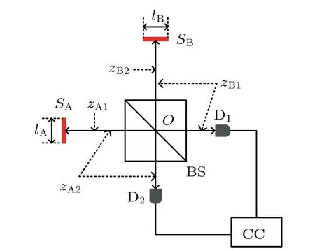
Fig.2.Two single-photon sources in an HOM interferometer.SA and SB are two independent single-photon sources. BS is a 50:50 nonpolarizing beam splitter. D1 and D2 are two single photon detectors.CC is a two-photon coincidence count system.lA and lB are the transverse sizes of SA and SB,respectively.zA1 is the lenth between SA and D1 via BS.zA2,zB1,and zB2 are defined similarly.
A more practical scheme shown in Fig.2 is employed for calculating the second-order interference of two independent photons in an HOM interferometer. SAand SBare two independent single-photon sources,which will emit single photons independently.The lAand lBare the transverse sizes of SAand SB,respectively. zA1is the distance between SAand D1via BS.zA2,zB1,and zB2are defined similarly.The probability amplitudes for these two photons to trigger a two-photon coincidence count in Fig.2 are represented byandrespectively.[26]is the two-photon probability amplitude corresponding to that the photon emitted by SAis detected by D1and the photon emitted by SBis detected byis the two-photon probability amplitude corresponding to that the photon emitted by SAis detected by D2and the photon emitted by SBis detected by D1.is the probability amplitude that the photon emitted by Sαtravels to Dj(α=A and B,j=1 and 2).If these two different ways are indistinguishable,the two-photon probability distribution in Fig.2 is[26]


where C.C.means complex conjugation.The first two terms on the right-hand-side of Eq.(5)represents a constant background in the second-order interference.The second-order interference pattern is described by the last two terms of Eq.(5).In the same condition,the first-order interference pattern at D1is

When photons emitted by SAand SBare independent,equals 0.The first-order interference pattern cannot be observed in this condition.Comparing Eqs.(5)and(6),the second-order interference pattern can be observed with two independent single-photon sources,while the first-order interference pattern cannot be observed in the same condition.
Equation(5)can be further simplified by taking Feynman’s photon propagator into consideration.We will calculate the term,for example.Other terms in Eq.(5)can be calculated in the same way.Substituting Eqs.(2)and(3)into,we have
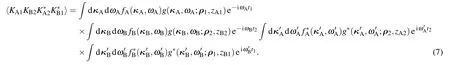
In a two-photon coincidence count event,KA1andcorrespond to the photon emitted by SAtravels to D1and D2simultaneously.The photon travels to D1in modeis the same as the one travels to D2in modein a two-photon coincidence count event.Hence it is reasonable to assume the following relationsandare satisfied.[34,36]Substituting the above relations into Eq.(7),we have
In order to simplify the calculation,we assume zA1=zA2=zB1=zB2=z and the spectrum distribution function is constant over the domain,

in which[ωα1,ωα2]is the integral domain of ωα(α=A and B).Taking Eq.(9)into consideration,equation(8)can be further simplified as


where paraxial approximation has been employed.It is complicate when both temporal and spatial parts are considered together.We will concentrate on the second-order temporal interference.Hence these two detectors are assumed to be in the symmetrical positions in the HOM interferometer,i.e.,equals. With this condition and quasi monochromatic light approximation,equation(11)can be simplified as

where

is the integral parameter. ωα0and ∆ωαare the central frequency and bandwidth of light emitted by source α,respectively.σαis the area of source α,which equals π(lα/2)2.z is the distance between the source and detector planes.∆ωAB(=|ωA0−ωB0|)is the difference between the central angular frequencies of the photons emitted by SAand SB.
In the same way as the one for the calculation ofone can simplify the other three terms in Eq.(5). With the definition of the normalized second-order coherence function given by Glauber,[37]equations(5)and(6)can be employed to calculate the normalized second-order temporal coherence function,

where ∆ω=2π∆ν is employed.The detail calculations can be found in Appendix A.Three different situations will be discussed in the following with the help of Eq.(13). Heralded single-photon source via entangled photon pairs and postselection is one of the widely applied single photon sources in multi-photon interference and the bandwidth of the generated single photon via this method can be as large as 70 nm.[38]Assuming a short wavelength laser at 351.1 nm is employed to pump a nonlinear crystal to generate entangled photon pairs.The central wavelength of the generated photons can be controlled via phase match condition and the bandwidth can be varied with different filters.[39]Wavelength,instead of frequency,is employed as the parameter in the following simulations.The relation,λ=c/ν,is employed to calculate frequency parameters via wavelength parameters.
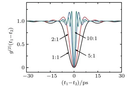
Fig.3. The second-order interference patterns of photons with same central wavelength and different bandwidths.∆λAB equals 0 nm,which means λA0=λB0.∆λB equals 1 nm.∆λA equals 1 nm,2 nm,5 nm,and 10 nm in different conditions.
In this condition,single photons emitted by these two sources have the same central wavelength and different bandwidths,which can be generated by degenerate parametric down conversion. The central wavelength of single-photon equals 702.2 nm.[39]The bandwidth is determined by the employed bandpass filter. Figure 3 shows the theoretical simulations for different bandwidths. When the bandwidths of these two photon beams are the same,g(2)(t1−t2)cannot be larger than 1,which can be seen from the 1:1 line in the figure.However,other three lines indicate that g(2)(t1−t2)can be larger than 1 when the bandwidths are different.The full width at half maximum(FWHM)of HOM dip of photons with the same central frequency and different bandwidths is mainly determined by the larger one,which can be clearly seen from the results in Fig.3.
In this condition,single photons emitted by these two sources have different central wavelengths and same bandwidth,which can be generated via non-degenerate parametric down conversion.Figures 4(a)–4(d)shows the simulated results when the wavelength difference equals 0 nm,1 nm,2 nm,and 5 nm,respectively.The bandwidths of both photons are 1 nm in the simulation.The central wavelengths of these two single-photon source should satisfy 1/λA0+1/λB0=1/λpdue to energy conservation,where λpequals 351.1 nm.When the frequency difference is less than the bandwidth,the beating cannot be observed in Fig.4(a).It is because the beating period is larger than the width of the temporal dip.When the frequency difference is larger than the bandwidth,the beating can be observed in the dip as shown in Figs.4(b)–4(d).The larger the frequency difference is,the higher the beating frequency is.

Fig.4. The second-order interference patterns of photons with different central wavelengths and same bandwidth.∆λA and ∆λB are both 1 nm.The central wavelength difference,∆λAB,equals 0 nm,1 nm,2 nm,and 5 nm in panels(a)–(d),respectively.
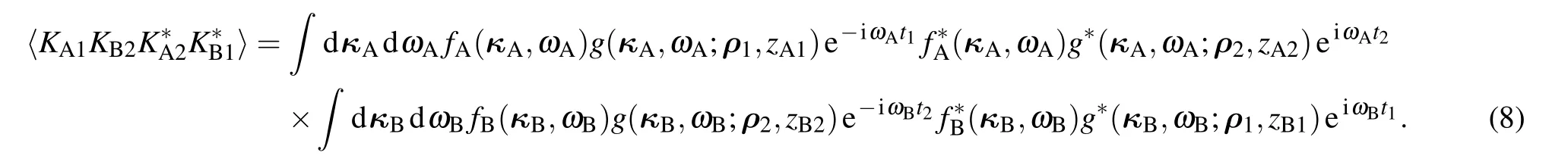
When the central wavelengths and bandwidths of the photons are different,the results are similar as the ones shonw in Fig.4 except the FWHM is determined by the photons with larger bandwidth.Figure 5 shows the simulated results when∆λB:∆λAequals 2:1.Beating can be observed when the frequency difference is larger than the bandwidth.
In the simulations of Figs.3–5,the response time of the detection system is assumed to be zero,in which the ideal interference pattern is observed. However,it is impossible to have detection system with zero response time in real experiments.Hence we will discuss how the response time of the detection system influences second-order interference pattern in the following.Taking the response time into consideration,the observed normalized second-order coherence function is[40]

in which,g(2)(t1−t2)is the normalized second-order coherence function,S(t1−t2−t0)is the window function and assumed to be a rectangular function centered at t0,T is the response time of the detection system. The following discussions are based on Eqs.(13)and(14).

Fig.5. The second-order interference patterns of photons with different central wavelengths and different bandwidths.∆λA equals 1 nm and ∆λB equals 2 nm.∆λAB equals 0 nm,1 nm,2 nm,and 5 nm in panels(a)–(d),respectively.
Fig.6.Detected HOM dip with different response time.∆λA=∆λB=1 nm and λA0=λB0=702.2 nm.τc is the coherence time of photons.N is an positive integer. is the observed second-order coherence function when the response time T of the detection system is taken into consideration.VT is the visibility of HOM dip for response time T,which is defined as
Figure 6(a)shows how the HOM dip varies as the response time of the detection system changes.The employed parameters in the simulations are as follows:∆λA=∆λB=1 nm,λA0=λB0=702.2 nm. When the response time of the detection system is 0 s,the detected HOM dip is an ideal dip with 100%visibility and g(2)(0)equals 0.When the response time of the detection system equals the coherence time of photons,τc,the observed HOM dip is almost identical as the ideal one and g(2)(0)equals 0.007.As the response time increases,the visibility of the detected HOM dip decreases and the FWHM of the dip increases.When the response time of the detection system equals 1000τc,the visibility decreases to 0.4%,which is impossible to observe in real experiments.The visibility is calculated viaand the same definition is also employed in Fig.7.The function(0)is the observed second-order coherence function when the response time T of the detection system is taken into consideration.
Figure 7 shows the influence of response time on the second-order interference pattern when the central frequencies of these two superposed photons are different.The employed parameters are ∆λA=∆λB=1 nm,λA0=701.2 nm,and λB0=703.2 nm.When the response time varies from 0 to 2τc,the visibility decreases while the interference patterns keep similar.When the response time equals 5τc,the interference pattern changes.The g(2)(0)becomes larger than 1.As the response time further increases,the visibility of the interference pattern decreases as shown by Fig.7(c). Figure 7(d)shows the same interference patterns as the ones in Fig.7(b)except vertical scales are different.

Fig.7.The second-order interference patterns with different response time.∆λA=∆λB=1 nm.λA0=701.2 nm.λB0=703.2 nm.The meanings of symbols are similar as the ones in Fig.6.
In Fig.6,the observed interference pattern is almost identical to the ideal one when the response time of the detection system is less than the coherence time of the superposed photons.When the frequencies of the superposed photons are different,the response time should be less than the coherence time of the photons or the inverse of the frequency difference of the superposed photons,depending on which one is less,to ensure that the observed interference pattern is similar as the ideal one. Further more,the response time of the detection system will change the interference pattern when the central frequencies of the superposed photons are different,as shown by the line with response time equaling 5τcin Fig.7(a).
4.Discussions
As stated in the introduction part,the reported experiments can be divided into two groups.[1–8,10,12–15]The difference between these two groups can be understood in Fig.8.The first group is shown in Fig.8(a). Even though these two photons are distinguishable,it is impossible to distinguish which photon comes from which input port of the HOM interferometer.There are filters before the detectors as shown in Fig.8(a),in which the photons with frequency ωjcan only pass the ωjfilter.The first way for photons to trigger a twophoton coincidence count event is photon A with frequency ω1travels to D1and photon B with ω2travels to D2.The second way is photon B with frequency ω1travels to D1and photon A with ω2travels to D2.If these two different ways to trigger a two-photon coincidence count event are indistinguishable in principle,the second-order coherence function is given by the same equation as Eq.(4).For instance,Ou and Mandel observed spatial quantum beating between 680-nm and 725-nm photons generated by parametric down conversion.[1]In their experiments,although the down-converted photons are distinguishable by their wavelengthes,it is impossible to tell which photon comes from which input port due to their experimental arrangement.There is two-photon interference.

Fig.8.Two-photon interference in an HOM interferometer.(a)Two photons are incident to one input port.(b)One photon is incident into one input port.
The second group of experiments is shown in Fig.8(b),in which the input photons are incident to the two input ports of an HOM interferometer,respectively.[13–15]If filters are put in front of the detectors as the one in Fig.8(a)in this condition,there is no interference.For there is only one possible way for these two photons to trigger a two-photon coincidence count event,which is photon A travels to D2and photon B travels to D1.Only when there are no filters,can beating be observed in Fig.8(b)as discussed in Section 3.In Ref.[13],Legero et al.observed beating between two independent single photons with frequency difference of 6π MHz in the experimental setup as the one shown in Fig.8(b).In their experiments,although they only employ one single-photon source,their experimental arrangement ensures that consecutive photons with different frequencies travel different paths and then arrive at the beam splitter simultaneously.Based on the above discussions,they can observe the second-order temporal beating when the frequencies of the input photons are different.
In Ref.[14],Bennett et al.observed HOM dip with independent photons of different bandwidths.In their experiments,one photon is emitted from a weak laser with nanoelectronvolt bandwidth.The other photon is emitted by a quantum dot with a few-microelectronvolt linewidth.The two different ways for these two photons to trigger a two-photon coincidence count event are indistinguishable,there are two-photon interference in their experiments.Based on the results shown in their experiments(Fig.3(e)of their paper),the frequency difference between the photons is less than a few-microelectronvolt,for there is no beating observed in their experiments. The reason why the visibility of the observed dip cannot reach 100%is due to the detected two photons may both come from the laser,which will contribute a constant background.No matter how weak the laser is,the possibility that two photons both coming from the laser will never vanish.[35]
In Ref.[15],Kaltenbaek et al.observed high visibility beating with chirped and anti-chirped laser pulses.The reason why they can observe beating is because they employed sum frequency generation as two-photon detection system(Fig.2(b)of their paper).Due to their experimental arrangement,only photons coming from different input ports will trigger a two-photon coincidence count event in the nonlinear crystal.There is no two-photon coincidence count when two photons coming from the same input port.This is the reason why the visibility of the observed beating can exceed 50%with classical light in their experiments.
5.Conclusions
In this paper,we have employed Feynman’s path integral theory to discuss the second-order interference of two independent photons with different spectra in an HOM interferometer.It is concluded that there are two-photon interference for photons with different spectra as long as the photons are indistinguishable for the employed detection system.The HOM dip can be observed with independent photons when these two detectors are in symmetrical positions in the HOM interferometer.When the frequency difference is larger than the bandwidth of the superposed photons,the second-order temporal beating can be observed within the dip.The visibility of the observed second-order interference pattern is dependent on the response time of the detection system.When the central frequencies of the superposed photons are different,the forms of the second-order interference patterns may be different when the response time of the detection system varies. The conclusions are helpful to understand the physics of two-photon interference and the applications of two-photon interference in quantum information.
Appendix A:Derivation of normalized second-order temporal coherence function
In order to calculate the following formula

we can first calculate
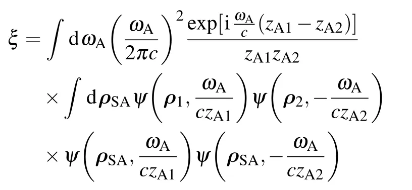
Substituting the propagation function,Eq.(3)into Eq.(A2),it is straightforward to have


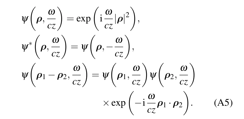
Substituting Eq.(A4)into(A3)and with the properties given by Eq.(A5),equation(A3)can be simplified as

The above equation can be further simplified when zA1=zA2=z is satisfied,i.e.,the distance between SAand the detector planes are equal.In this condition,equation(A6)is

When these two detectors are in symmetrical positions,i.e.,
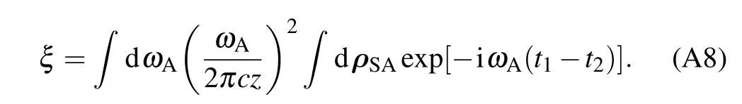
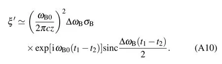
With quasi-monochromatic light,equation(A8)can be approximated as

where circular light source is assumed and σAis the size of the source.∆ωAis the bandwidth of light emitted by SA.With the same method,the second factor of Eq.(A1)can be calculated as
Hence we have

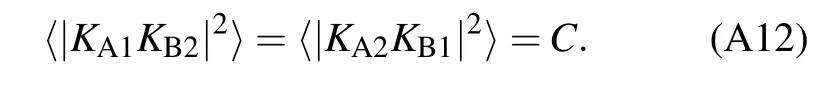
where

is the integral parameter. ωα0and ∆ωαare the central frequency and bandwidth of photons emitted by source α,respectively.σαis the area of source α,which equals π(lα/2)2.z is the distance between the source and detector planes.We have assumed zA1=zA2=zB1=zB2=z.∆ωAB=|ωA0−ωB0|is the frequency difference between the central frequencies of photons emitted by SAand SB.
With the same method as the one above,we have
When these two detectors are in symmetrical positions,i.e.,and z1=z2,equation(5)can be simplified as
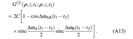
Based on the definition given by Glauber,[37]the normalized second-order coherence function is
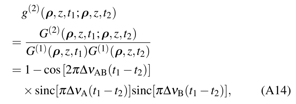
in which ∆ω=2π∆ν is employed.Thus equation(13)is obtained.
猜你喜欢
Chinese Physics B(2022年9期)2022-09-24
Chinese Physics B(2022年7期)2022-08-01
保健与生活(2022年8期)2022-04-08
旅游世界(2021年5期)2021-11-07
现代畜牧科技(2021年2期)2021-03-19
民间文学(2019年12期)2019-05-26
男生女生(银版)(2016年5期)2017-01-17
男生女生(银版)(2016年5期)2017-01-17
中国现当代社会文化访谈录(2016年0期)2016-09-26

- Chinese Physics B的其它文章
- Compact finite difference schemes for the backward fractional Feynman–Kac equation with fractional substantial derivative*
- Exact solutions of a(2+1)-dimensional extended shallow water wave equation∗
- Lump-type solutions of a generalized Kadomtsev–Petviashvili equation in(3+1)-dimensions∗
- Time evolution of angular momentum coherent state derived by virtue of entangled state representation and a new binomial theorem∗
- Boundary states for entanglement robustness under dephasing and bit flip channels*
- Manipulating transition of a two-component Bose–Einstein condensate with a weak δ-shaped laser∗