
An improved lumped parameter model predicting attenuation of earmuff with air leakage
2022-11-21 09:29XuZhong仲旭ZheChen陈哲andDongZhang章东
Chinese Physics B 2022年11期
Xu Zhong(仲旭), Zhe Chen(陈哲), and Dong Zhang(章东)
Key Laboratory of Modern Acoustics,Institute of Acoustics,Nanjing University,Nanjing 210093,China
Since air leakage is inevitable when earmuffs are worn improperly or together with safety glasses in factory or military,it is required to be considered to accurately predict earmuff attenuation. Besides unwanted air leakage,under controlled air leakage is introduced to earmuff to achieve adjustable attenuations in different signal-to-noise ratios (SNRs) and balance between attenuation and speech intelligibility. This work is to develop an improved lumped parameter model (LPM) to predict earmuff attenuation with consideration of air leakage. Air leakage paths are introduced into conventional LPM without air leakage, and air leakage path impedance is analytically described by Maa’s microperforated tube impedance.Earmuff passive attenuation behavior can be analytically described and analyzed with the improved LPM. Finally, the validity of improved LPM is verified experimentally. The results indicate that the improved LPM can predict earmuff attenuation with air leakage,and air leakage deteriorates earmuff attenuation and turns resonance frequency higher.
Keywords: earmuff,lumped parameter model,air leakage,attenuation
1. Introduction
Earmuff has been widely used for hearing protection due to its advantages of low cost,simple implementation and good performance. There are lots of studies about earmuff attenuation performance, because earmuffs are designed to attenuate noise and protect hearing. Carilloet al.studied earmuff attenuation related vibro-acoustic response with numerical model.[1]Baiet al.studied earmuff passive attenuation and active noise control (ANC) performance with electroacoustic lumped parameter model (LPM).[2]Basically, there are two kinds of models for earmuff passive attenuation performance analysis. One is LPM, which is the first proposed model when computer technology was not fully developed.[2–8]The other is numerical model which includes finite element model(FEM) and boundary element model (BEM) with the development of computer technology.[1,6,8–10]Typically,there exist four sound paths as sound reaches internal ear,[11]i.e.,path(a)is the pumping motion of cup which is vibroacoustic behavior; path (b) is the air leakage path; path (c) is direct sound transmission through earmuff; path (d) is bone conduction(BC)which means sound transmits through bones and tissues other than air propagation. Boyeret al. indicated that passive attenuation is dominant by path (a) and path (b) at low frequencies.[11]Since conventional LPM simulates path (a)and sound wave length is much higher than earmuff dimension at low frequencies,it is reasonable to analyze the earmuff passive attenuation without air leakage at low frequencies with conventional LPM. Air leakage is inevitable when earmuffs are worn improperly or together with safety glasses in factory or military. Besides unwanted air leakage, under controlled air leakage is introduced to earmuff to balance between attenuation and speech reception.[12]Zwislocki suggested that electro-acoustic circuit can study the influence of air leakage on attenuation.[3]However, the air leakage path impedance could not be described analytically by Zwislocki. Since there were no analytic solutions available, researchers experimentally studied the influence of air leakage on earmuff attenuation performance, and concluded that the air leakage path would deteriorate attenuation a lot.[13]Allen and Berge also studied the level-dependent attenuation of earmuff with the controlled air leakage experimentally.[12]The reduced attenuation is of benefit to speech reception with the controlled air leakage at overall sound pressure less than 110 dB, and attenuation decreases less at overall sound pressure higher than 110 dB where non-linearity happens. The air leakage was designed ahead with fixed parameters in Allen study, and adjustable attenuation was achieved by non-linearity. In this study all analysis was conducted under the condition of overall sound pressure less than 110 dB without non-linearity,and adjustable attenuation can be achieved by tuning air leakage such as changing radius or length of air leakage. Paurobally and Pan studied earmuff mechanisms with air leakage by acoustic propagation equation,where air piston radiation impedance was described as air leakage path impedance and analytically solved at low frequencies.[14]However,air leakage paths,both unwanted and controlled, are normally at a millimeter level
where heat dissipation should be taken into account, it is unsuitable to replace air leakage impedance with air piston radiation impedance in their analytical solution, and experiments in their study only demonstrated the trend of how air leakage interacted with attenuation but they did not specify the comparison between experimental results the analytical simulations. Kalb proposed an electro-acoustic circuit to describe both path (a) and path (b) with LPM.[15]Unfortunately, each element in the circuit could not be analytically described,and its value was derived by using iterative trails to match experimental result instead.
So far there has been no analytical solution which can describe air leakage actual influence on earmuff passive performance,so a numerical model was required to predict earmuff attenuation performance with air leakage.The present study is to derive analytical solution with improved LPM which contains both path(a)and path(b). Firstly,impedance of path(b)which was derived from microperforated tube impedance in Maa’s study,[16]is introduced into conventional earmuff LPM which only contains path (a). The analytical expression of each element in circuit is given, and analytical solution of earmuff passive attenuation with air leakage can be derived.Secondly, the influence of earmuff and air leakage parameters on passive attenuation performance are systemically analyzed based on analytical solution. Finally, validation of analytical solution is examined experimentally. With the help of this improved LPM,earmuff attenuation performance with both unwanted and wanted air leakage can be predicted, and the adjustable attenuation earmuff can be designed by tuning air leakage, for instance by adjusting air leakage radius and length or adjusting ratio of opened air leakage to all air leakage with multiple adjustable air leakage introduced into earmuff intentionally. The earmuff user can adjust attenuation manually, depending on noise level and SNR,such as adjusting it to high attenuation in high noise environment (overall noise level more than 70 dBA)to improve both noise attenuation and speech intelligibility,whilst adjusting it to low attenuation in medium noise environment (overall noise level less than 70 dBA) which is of benefit to speech intelligibility and still provides moderate noise attenuation in the same time.[17]
2. Theoretical analysis
Figure 1(a) shows the diagram of earmuff with air leakage. The controlled air leakage,which is cylinder-shaped tube with radiusaand lengthl,can be utilized to adjust attenuation.The air leakage tube can be installed either on cushion or on cup shell. The rest of model is the same as the conventional earmuff.[6,7]The earmuff equivalent mass and volume areMmandVsrespectively. The earmuff cushion stiffness,resistance and coverage area areKm,Rm,andSsrespectively.Figure 1(b)shows the corresponding electro-acoustic analogy diagram,
whereMm/(Ss)2,Rm/(Ss)2, andKm/(Ss)2are combined to obtain acoustic impedance jωMm/S2s+Rm/S2s+Km/jωS2sof path (a);Zleak1toZleaknis acoustic impedance of each air leakage of path (b), respectively;KA/jω(Ss)2is acoustic impedance of earmuff cup cavity. Note that path (b) is new added air leakage path element while the others are the same as those of conventional earmuff model without air leakage in previous paper.[6,7]In comparison with the scenario of conventional LPM model without air leakage,the sound transfers through not only earmuff path (a) but also path (b) air leakage into ear. According to electro-acoustic analogy diagram as shown in Fig. 1(b), the transfer path between inside and outside pressure of earmuff without air leakage path (b) can be written as[6,7]
whereMm=Mv+Mc/3 is the equivalent mass,Mvis the earmuff cup mass,Mcis the earmuff cushion mass,RmandKmare the cushion resistance and stiffness,Vsis the earmuff volume,ρis the air density,andcis the sound speed.

Fig.1. (a)Structure illustration and(b)electro-acoustic analogy diagram of earmuff with air leakage.


wherekis the wave number and given as
The attenuation can be derived in frequency domain as follows:

Although equations (4) and (14) hold true on the assumption that the air leakage is cylinder shaped, these equations still work if the cross section of air leakage is not circular except that cross section is a slit,and slit is defined as the ratio of the longest edge length to the shortest edge of air leakage cross section,with value being more than 10,if cross section is polygon. The equivalent radiusacan be calculated by
whereSleakis the area of air leakage’s cross section.The closer to 1 the ratio of the longest edge length to the shortest edge,the better the equation (15) works. Taking the earmuff worn together with safety glass in factory or military for example,the air leakage with triangle-shaped cross section always exists between cushion, flesh and glass leg. In this case, equation(15)can be used to calculate equivalent radius.
3. Numerical simulations and experiments
3.1. Numerical simulations
In Table 1 listed are the values of commercial earmuff and air leakage parameters which were used in the following experiment. The earmuff parameters,i.e., stiffness and resistance of cushion were estimated experimentally by an impact hammer testing or fitting procedure.[2,6,19]The other earmuff parametersVs,Ss, andMmwere also measured accordingly from the commercial earmuff.[19]The air leakage parameters,i.e.,lengthland radiusawere measured from one Teflon tube used in the following experiment.

Table 1. Typical lumped parameters of commercial earmuff and air leakage.
To study the influence of earmuff parameters on attenuation with and without air leakage,two extra values of each parameter were selected in the simulation besides typical value.Taking the reference values from previous study and considering realistic condition,[19]the variance of mechanical parameterKmandRmwere both set to be lower than 20% of typical values;the variance of earmuff geometry parameterVsandSsand mass parameterMmwere all set to be lower than 10% of typical values; the air leakage radius was set to be at a millimeter level according to the safety glass leg thickness and earmuff adjustable tube radius;the air leakage length was set to be at a centimeter level according to the earmuff cushion width and adjustable tube length;analysis frequency lower range was set to be 100 Hz considering both previous several studies and noise source cut-off frequency in the next section of experiment,[1,3,6]and higher range was set to be 800 Hz below which LPM works and attenuation is dominated by transfer path(a)and path(b).[11]
Figure 2 shows the influence of air leakage parameters(length or radius)on attenuation,where only one parameter is changed while other parameters are fixed as typical parameters listed in Table 1. For comparison,the curve of attenuation versus frequency without air leakage is also given in Fig. 2.It is found that air leakage will deteriorate the attenuation almost to the same extent in the whole analysis frequency range and the resonant frequencies shift toward higher frequencies slightly. In Fig. 2(a), as the length of air leakage increases from 1.5 cm to 2.5 cm, attenuation slightly increases around 0.9 dB in the whole analysis frequency range, and resonant frequency shifts 2 Hz toward lower frequencies. In Fig.2(b),as the radius of air leakage increased from 0.5 mm to 2 mm,attenuation greatly decreased around 5.7 dB in the whole analysis frequency range,and resonant frequency shifts 9 Hz toward higher frequencies. The results suggest that shorter the length and the larger the radius of air leakage,the less the attenuation is and the higher the shift resonant frequency.

Fig.2. Influence of air leakage parameters on earmuff attenuation,showing frequency-dependent(a)length and(b)radius,on earmuff attenuation.
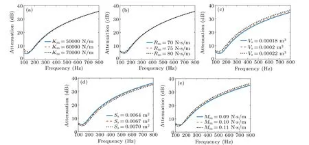
Fig.3. Influence of earmuff parameters on earmuff attenuation,showing frequency-dependent(a)cushion stiffness,(b)cushion resistance,(c)volume,(d)coverage area,and(e)equivalent mass.
Figure 3 illustrates the influence of earmuff parameters on attenuation with air leakage, where only one parameter is changed while other parameters are fixed as typical parameters listed in Table 1. In Fig.3(a),the increase of cushion stiffnessKmleads the resonant frequency to increase(about 20 Hz),the attenuation below resonant frequency to increase, and the attenuation above resonant frequency to decrease slightly. The maximum attenuation variation is about 2.6 dB in the analysis frequency. In Fig.3(b), the increase of cushion resistanceRmcauses the resonant frequency to increase (about 6 Hz).The cushion resistanceRmalso controls the system resonant amplitude,and the damping grows with the increase of attenuation(around 1.1 dB)at resonant frequency. In Fig.3(c),the increase of earmuff volumeVsleads the resonant frequency to increase (about 6 Hz), and also the attenuation (around 1.9 dB)to increase in the whole analysis frequency range. In Fig.3(d),the increase of earmuff coverage areaSscauses the resonant frequency to increase (about 4 Hz), and also the attenuation to decrease (around 1.3 dB) in the whole analysis frequency range. In Fig. 3(e) the increase of earmuff equivalent massMmresults in the decrease of resonant frequency(about 8 Hz), and also in the decrease of attenuation below resonant frequency and the increase of attenuation above resonant frequency,where the maximum attenuation variation is 1.4 dB in the analyzed frequency range. The results in Fig.3 demonstrate two suggestions. First,three parameters(volumeVs, coverage areaSsand equivalent massMm) are more critical to the control of attenuation with air leakage. Second,the trend of earmuff parameters influence on attenuation with air leakage is similar to that without air leakage,[7]so the method to design high attenuation earmuff under the condition of no air leakage also works for the case with air leakage.
3.2. Experiments
In order to examine the validity of the proposed model,experiments were carried out in the anechoic chamber of Nanjing University. The earmuff was fitted to a head and torso simulator B&K 4128C and only one side of earmuff was tested experimentally. The outside microphone was located centrally on the outer side of earmuff and was about 1 cm away from earmuff shell. The microphone in the ear of B&K 4128C was used to measure the sound pressure inside the earmuff.The primary source cutoff frequency was around 100 Hz and placed about 1 m away from the earmuff,ensuring plane sound wave at earmuff location. A broadband white noise with a bandwidth of 0 kHz–3 kHz was fed to noise source, signals measured by the outside microphone and inside microphone were recorded by B&K front end 3560D as the signalx(n)outside earmuff and signald(n)inside ear respectively as shown in Fig.4(a).Dummy head ear canal transfer function was used to correctd(n) to obtain the signale(n) inside earmuff. In Fig. 4(b), the earmuff was fitted tightly on the dummy head without air leakage. In Fig. 4(c), a teflon tube was inserted between earmuff cushion and dummy head to introduce a controlled air leakage,the blue material around tube was of plasticine to avoid any unwanted air leakage around the tube. Figure 4(d)shows a close view of two teflon tubes with the same length of 2 cm and two different inner radii of 1 mm and 2 mm.
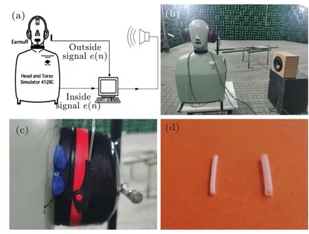
Fig. 4. Schematic diagram and photos of experiment setup, showing (a) experiment schematic diagram,(b)panorama view of experiment under the condition of no air leakage, (c)close view of experiment under the condition of air leakage,(d)close view of air leakage tubes with the same length and two different inner radii.

Fig.5. Simulated and measured curves of earmuff attenuation versus frequency, (a)without air leakage, (b)with one air leakage of radius 1 mm and length 2 cm,(c)with two identical air leakage with dadius 1 mm and length 2 cm,(d)with one air leakage of radius 2 mm and length 2 cm.
The simulated and measured curves of earmuff attenuation versus frequency without and with air leakage are matched as shown in Fig.5,where the dashed line represents the simulated curve calculated by the improved LPM with the earmuff parameters in Table 1 and various air leakage parameters,and the solid line denotes the measured curve.Figure 5(a)shows the comparison between simulated results and measured results in the absence of air leakage. Figures 5(b)–5(d)show the comparison between simulated and measured results in the presence of air leakage,where one air leakage path has inner radius 1 mm and length 2 cm in Fig. 5(b), two identical air leakage paths with both inner radii 1 mm and length 2 cm in Fig. 5(c), and with one air leakage path with inner radius 2 mm and length 2 cm in Fig.5(d). Compared with attenuation in the absence of air leakage,the attenuation of one air leakage path with inner radius 1 mm and length 2 cm is lower than about 2.0 dB in the whole analysis frequency range and resonant frequency shift is higher than 7 Hz;the attenuations of two identical air leakage paths both with inner radius 1 mm and length 2 cm are lower than about 3.6 dB in the whole analyzed frequency range and the resonant frequency shift is higher than 9 Hz;the attenuation of one air leakage path with inner radius 2 mm and length 2 cm is lower than about 6.3 dB in the whole analyzed frequency range and resonant frequency shift 11 Hz toward higher frequencies. Generally,with the increase of overall cross section of air leakage, the attenuation decreases in the whole analyzed frequency range and resonant frequency shift toward higher frequencies.
4. Discussion
Paurobally and Pan developed an analytical solution by replacing air leakage impedance with air piston radiation impedance, and experiments were conducted to only demonstrate air leakage influence on attenuation while no specified parameters were given to compare test results with simulation results.[14]Figure 6 illustrates the comparison between solution of Paurobally and Pan,and the solution this paper for the case of one air leakage path with typical parameters in Table 1.The measured result is also given for comparison,showing inappropriate air leakage impedance especially insufficient air leakage resistance in Paurobally and Pan’s solution. Paurobally and Pan’s analytic solution did not consider the heat dissipation(Rto>10). Nevertheless the heat dissipation needs taking into account since air leakage radius is always at a millimeters level which is at the same level as boundary layer.
The influences of earmuff and air leakage parameters on attenuation were studied by simulations based on the improved LPM. The simulation results indicate that the cross section area in air leakage parameters is critical for attenuation performance. Therefore,for achieving high attenuation,it is important to design an appropriate cushion to minimize or avoid air leakage with large cross section area between flesh and cushion. The simulation results also demonstrate that the trend of earmuff parameters influencing attenuation with air leakage is similar to that without air leakage, so the optimal earmuff parameters for achieving the good attenuation performance in absence of air leakage are also an optimal ones in the presences of air leakage. For designing the attenuation adjustable earmuff,it is achievable by tuning the radius of controlled air leakage or adjusting the ratio of opened air leakage to all air leakage with multiple adjustable air leakage introduced into earmuff intentionally.

Fig.6. Comparison between Paurobally and Pan’solution,and the solution in this paper for the case of one air leakage path with typical parameters in Table 1.
Nowadays ANC earmuffs are becoming more and more popular,the conventional LPM has been widely used to study the ANC earmuff performance.[2]Since air leakage often exists when ANC earmuff is worn,the ANC earmuff attenuation performance with air leakage will be investigated with the improved LPM in future study. In addition,ANC earmuffs combined with acoustic meta-surfaces can be utilized to enhance the attenuation at low frequencies,[20–22]which will also be investigated by using the improved LPM in future study.
5. Conclusions
In conclusion, an improved LPM has been developed to predict and analyze actual earmuff attenuation with air leakage. The air leakage impedance is derived from Maa’s microperforated tube impedance. Based on improved LPM, the influence of earmuff and air leakage parameters on passive attenuation performance are systemically analyzed. Finally,experiments are performed to confirm the validation of analytical solution. The results indicate that the cross section area in air leakage parameters is critical for attenuation performance,the influence of earmuff parameters on attenuation with air leakage is similar to that without air leakage. With help of the improved LPM,earmuff attenuation performance with unwanted and wanted air leakage can be predicted,and adjustable attenuation earmuff can be designed by tuning air leakage.
Acknowledgement
Project supported by the National Natural Science Foundation of China(Grant Nos.11934009 and 11874216).

- Chinese Physics B的其它文章
- A design of resonant cavity with an improved coupling-adjusting mechanism for the W-band EPR spectrometer
- Photoreflectance system based on vacuum ultraviolet laser at 177.3 nm
- Topological photonic states in gyromagnetic photonic crystals:Physics,properties,and applications
- Structure of continuous matrix product operator for transverse field Ising model: An analytic and numerical study
- Riemann–Hilbert approach and N double-pole solutions for a nonlinear Schr¨odinger-type equation
- Diffusion dynamics in branched spherical structure