
A design of resonant cavity with an improved coupling-adjusting mechanism for the W-band EPR spectrometer
2022-11-21 09:27YuHe贺羽RunqiKang康润琪ZhifuShi石致富XingRong荣星andJiangfengDu杜江峰
Chinese Physics B 2022年11期
Yu He(贺羽) Runqi Kang(康润琪) Zhifu Shi(石致富)Xing Rong(荣星) and Jiangfeng Du(杜江峰)
1CAS Key Laboratory of Microscale Magnetic Resonance and School of Physical Sciences,
University of Science and Technology of China,Hefei 230026,China
2CAS Center for Excellence in Quantum Information and Quantum Physics,University of Science and Technology of China,Hefei 230026,China
3Chinainstru&Quantumtech(Hefei)Co.,Ltd,Hefei 230031,China
We report a new design of resonant cavity for a W-band electron paramagnetic resonance(EPR)spectrometer. An improved coupling-adjusting mechanism,which is robust,compact,and suits with both solenoid-type and split-pair magnets,is utilized on the cavity,and thus enables both continuous-wave(CW)and pulsed EPR experiments. It is achieved by a tiny metal cylinder in the iris. The coupling coefficient can be varied from 0.2 to 17.9. Furthermore,two pistons at each end of the cavity allow for adjustment of the resonant frequency. A horizontal TE011 geometry also makes the cavity compatible with the two frequently used types of magnets.The coupling-varying ability has been demonstrated by reflection coefficient(S11)measurement. CW and pulsed EPR experiments have been conducted. The performance data indicates a prospect of wide applications of the cavity in fields of physics,chemistry and biology.
Keywords: electron paramagnetic resonance,W-band,microwave cavity,coupling coefficient
1. Introduction
Electron paramagnetic resonance (EPR) spectroscopy is widely used in many fields, such as biology,[1–3]chemistry,[4,5]and physics.[6,7]Developments of superconducting magnet[8,9]and microwave technology in the terahertz region[10,11]have created a boom in high-field/highfrequency EPR(HF-EPR).It offers many advantages over traditional EPR spectroscopy, such as S-band and X-band EPR.HF-EPR provides higher spectral resolution, stronger orientational selectivity and less requirement on sample volume,and opens the path to understanding the fast motional dynamics of molecules.[12]Some analogous technologies, such as nuclear magnetic resonance (NMR)[13]and muon spin rotation/relaxation/resonance(μSR),[14]also benefit from highfrequency high-magnetic field.[15,16]
A microwave (mw) resonator is one of the most significant parts in an EPR spectrometer since it greatly influences the performance of the spectrometer. At W-band, a singlemode cavity is usually the best choice for resonance because of its high microwave-power-to-magnetic-field conversion factor,relatively high filling factor and appropriate size.[17,18]These properties result in a high sensitivity and make the cavity easy to fabricate. When the microwave is coupled into the resonant cavity,it generates an oscillating magnetic fieldB1,perpendicular to the external static magnetic fieldB0. If the frequency of microwave matches the splitting of the energy levels of the sample, resonance absorption will occur. Coupling between the cavity and the waveguide is achieved through a hole(iris).The coupling strength is characterized by the coupling coefficientβ, which is defined as the ratio of energy leakage from the iris to the energy loss in the cavity wall and the sample.
Generally,both continuous-wave(CW)and pulsed experiments are desired in studies. The ability to delicately adjust the coupling strength is significant in CW experiments for perfect impedance matching and maximized sensitivity.On the contrary,overcoupling is demanded in pulsed EPR for broad bandwidth, high sensitivity, and short deadtime.[19]As a result, the coupling strength between the cavity and the input/output waveguide should be adjustable among critical coupling and overcoupling, so that the coupling coefficient can cover the need for both CW and pulsed experiments. This is challenging for the design of cavities, especially for highfrequency cavities,such as cavities for W-band EPR.
Changing the size of the iris by a screw is the most general means to vary coupling.[17,19,20]However, as the frequency goes high, the size of cavities shrinks with the mw wavelength. Therefore, the coupler has to be extremely small.Similar designs, where the coupling strength is changed by a sliver sphere held by a thin rod[21]or a sliver plated needle,[22]prove to be feasible at W-band. However, such structures are hard to fabricate, fragile, and peculiarly prone to suffer from microphonic effects. Many other methods for adjustment of coupling strength at W-band have also been developed. One idea is to change the polarization of the travelling wave in the waveguide relative to the standing wave in the cavity. This can be realized by a series of twists in a circular waveguide.[23]However, in rectangular waveguides, which has much larger bandwidth for only a single mode,this method is invalid. Another way is simply rotating the whole cavity,but the range and precision of variation cannot be balanced.[24,25]The Gordontype coupler also has the potential to be applied in W-band cavities,but it allows only a narrow adjustable range,and fails to achieve strong overcoupling.[26]
In this work,we report a novel design of resonant cavity.The cavity operates on the T011mode with its cylindrical axis in the horizontal plane,so it is compatible with both solenoids and split-pair magnets. A novel variable coupling mechanism using a teflon-held metal cylinder is applied. It is robust and compact. Remote control is also feasible through such design.The coupling coefficient can be varied from 0.2 to 17.9. Three modulation coils are integrated with the cavity.They are selectively activated depending on the working conditions.A series of experiments are conducted to test the cavity. The couplingadjusting ability is verified and the performance of the cavity is demonstrated by CW and pulsed EPR experiments.
2. Design
The structure of the cavity is shown in Fig.1.It is a cylindrical brass cavity [Fig. 1(a1)] operating on the TE011mode,which is similar to that described before.[24]The inner diameter of the cavity is 4.22 mm. The inner surface of the cavity is plated with silver to improve theQfactor,and thus enhance the sensitivity.
A Teflon plunger[Fig.1(a4)]holding a tiny metal cylinder [Fig. 1(a2)] is inserted in the end of the copper flange[Fig. 1(a3)]. The flange is used for connecting the cavity to the rectangular waveguide tube, and is fastened to the cavity by a hoop [Fig. 1(a5)]. Variable coupling is achieved by the metal cylinder, which is inserted into the tail of the plunger and plugged into the 1.1-mm (inner diameter) coupling hole of the cavity. The plunger is rigid enough, so the coupling mechanism does not suffer from microphonic effects. The cylinder is plated with gold, which has two functions: reducing the loss of the microwave and protecting the cylinder from being oxygenated. Moving the cylinder up and down by two gears[Fig.1(a6)]sandwiching the head of the plunger changes the coupling strength between the cavity and the waveguide.This can be achieved automatically through a motor with a gear. The coupling strength can be varied among undercoupling(down to 0.2),critical coupling and overcoupling(up to 17.9). A typical loadedQfactor of the cavity at critical coupling is 2000.
The resonant frequency of the cavity has a variation range from 92.3 GHz to 95.6 GHz. Delicate resonant frequency adjustment is realized by moving the pistons [Fig. 1(a8)] at the two ends of the cavity in and out, which changes the length of the cavity. A micrometer-like structure,including the screw threads on the pistons and the main body of the cavity,together with the sleeves[Fig.1(a7)],allows for subtle adjustments of the position of the pistons.

Fig. 1. (a) Schematic diagram of the resonant cavity. (b) Photograph of the actual cavity. (1)The main body of the cylindrical cavity,(2)the coupling adjusting cylinder, (3) the flange that connects the cavity to the waveguide,(4)the Teflon plunger that holds the coupling adjusting cylinder,(5)the hoop,(6)the gears used for moving the Teflon plunger,(7) sleeves of the pistons, (8) the tuning pistons, (9) the Teflon of the modulation coils,(10)and(11)the modulation coils.
The direction of the microwave magnetic fieldB1is along the cylindrical axis of the cavity,e.g., always in thexyplane. Therefore, no matter whether the external magnetic fieldB0is provided by solenoids,along thez-axis,or by splitpair magnets, in thexy-plane, we can always find a direction whereB1is perpendicular toB0. Three coils wounding around the Teflon support[Fig.1(b9)]provide the modulation fields. When the cavity operates in a solenoid, the coil below[Fig.1(b11)]is activated to generate a vertical modulation magnetic field. In the split-pair-magnet case, the horizontal modulation coils [Fig. 1(b10)] enable us to provide modulation magnetic field in the same direction as the external field.For effective penetration of the modulation field,the modulation frequencyfmis set to 6.25 kHz.
The sample area is up to 0.9 mm in diameter. In this region,the magnetic field reaches the strongest and the electric field is almost zero. During experiments, samples in a sample tube are loaded into the cavity from the hole at the axis of the piston. The microwave-power-to-magnetic-field conversion factor is 4.7 Gauss/W1/2obtained by Rabi oscillation experiment described in the following. Such a relatively high conversion factor allows high signal-to-noise ratio even at low sample concentrations and shortπandπ/2 pulses.
3. Experimental setup
For testing of this novel resonant cavity, a W-band EPR spectrometer named EPR-W900, which has been developed by University of Science and Technology of China and Chinainstru & Quantumtech (Hefei) Co.,Ltd, is utilized. As shown in Fig.2,besides the cavity,the spectrometer includes two magnets and a microwave bridge.
3.1. Magnets
Two types of magnets have been utilized in our experiments to show that the cavity can be used with these magnets. One is a solenoid-type magnet[Fig.2(a)],which is produced by Cryomagnetics Inc. The other is a split-pair magnet[Fig.2(b)]. For the split-pair magnet,two pairs of Helmholtz coils are used to provide the external field. All of them are cooled down to below 3 K using a Gifford–McMahon cryocooler and compressor so that the coils are superconductive. The compressor is cooled by water. The current passing through the main coils can be at most 162 A, creating a static magnetic field up to 6 T. High electrical inductance of the main coils limits the rate of change of current(≤0.02 A/s).For saving time when conducting narrow filed-swept experiments, a second pair of field-sweeping coils is used. The field-sweeping coils carry currents from-40 A to 40 A,corresponding to the magnetic field from-0.1 T to 0.1 T,and the maximum rate of change of current on it is 1.6 A/s.

Fig. 2. (a) Block diagram of the W-band EPR spectrometer equipped with a solenoid-type magnet. (b) Block diagram of the W-band EPR spectrometer equipped with a split-pair magnet. (c) The detailed information about the W-band EPR spectrometer. The Helmholtz coils are cooled down to below 3 K to maintain superconductive. The W-band mw bridge is built based on an X-band mw bridge we developed before.The X-band mw bridge outputs and processes a 9–10-GHz IF mw signal. Box 1 stands for the transmitter part. An 84.5-GHz microwave is generated and mixed with the IF signal, forming a 93.5–94.5-GHz W-band microwave. The mw bridge is able to operate in both CW and pulsed modes. Switching between the two modes is realized by two switches. Box 2 stands for the receiver part. The EPR signal is amplified by a low-noise amplifier (LNA) and mixed with the 84.5-GHz reference signal. The output IF signal is fed into the X-band mw bridge and further processed. Amp.: amplifier,Att.: attenuator,Cir.: circulator.
3.2. Microwave bridge
The W-band microwave bridge is shown in Fig. 2(c).It is based on an X-band microwave bridge we developed before,[27]which outputs and receives a 9–10 GHz intermediate frequency(IF)mw signal. A mw signal of 10.5625 GHz is generated by a mw source and octupled and filtered,forming an 84.5-GHz microwave. It is used to convert an X-band signal to a W-band one or vise versa,enabling W-band excitations and readouts. One arm of the 84.5-GHz mw is up-converted with an IF signal of 9–10 GHz to form a W-band signal of 93.5–94.5 GHz. Then the W-band mw signal is filtered and amplified by a band-pass filter(BPF)and an amplifier before the mode-selecting switch. In the CW mode, the mw signal straightly passes the switch and a variable attenuator, then is fed into the cavity through a circulator. In the pulsed mode,a cascade of an amplifier, an isolator and a switch driven by high-speed square waves is inserted between the amplifier and the variable attenuator. Switching between the two modes is controlled by the computer. Another arm of the 84.5-GHz mw is mixed with the EPR signal amplified by a low-noise amplifier (LNA). The output of the mixer is an IF signal of 9–10 GHz,which is then processed by the X-band mw bridge.
4. Performance
The ability of the cavity to change the coupling strength is demonstrated by reflection coefficient(S11)measurement. For testing the EPR performance of the cavity, both continuouswave experiments and pulsed experiments are carried out.
4.1. Coupling adjusting ability
We test the reflection coefficient (S11) at different coupling strengths of the empty resonant cavity. The mw frequency is swept from 93.77 GHz to 94.77 GHz. Power of the reflected microwave is measured and plotted in Fig.3. The black lines show experimental data. They are fitted by using the equation

whereQ0is the unloaded quality factor,f0is the resonant frequency,βis the coupling coefficient, andbis a constant that reflects the transmission loss outside the cavity. Fitting results are shown as the red dotted lines. Reflection coefficient measurement at critical coupling(β=1)is shown in Fig.3(a).The extremely sharp and deep absorption peak is a symbol of high frequency selectivity and strong absorption,which is preferred in CW EPR experiments.The fitted value ofQ0is 4066,so the loaded quality factor,defined asQ=Q0/(1+β),is 2033.

Fig.3.Reflection coefficient S11 versus frequencies under different coupling conditions. The black lines are the experimental data and the red dotted lines are the fitting results. (a) Reflection coefficient at critical coupling. (b) Reflection coefficient at undercoupling. (c) Reflection coefficient at overcoupling.
Figure 3(b)shows the undercouplingS11curve. The absorption peak is narrow but shallow,indicating relatively high frequency selectivity but weak absorption. Here,βis fitted to be 0.2. The condition of overcoupling is shown in Fig. 3(c).The peak is very shallow and broad. This is because in overcoupling status the cavity is able to absorb microwaves in a wide range of frequencies,resulting in a broad bandwidth.The fitted value ofβis 17.9. Pulsed EPR experiments are carried out in this range.
4.2. CW EPR experiment
For testing the continuous-wave EPR performance of the cavity,field-swept EPR experiments at room temperature with starch and lignite powder were carried out.CW EPR is utilized for analyzing the properties and structures of materials.[28,29]Nitrogen oxide radicals are tagged to starch molecules by chemical synthesis. For the sample being starch, both Xband and W-band room temperature powder EPR spectra have been recorded as shown in Figs.4(a)and 4(b). The solid blue lines stand for the experimental result and the dashed red lines stand for the simulation. For the W-band EPR experiment in Fig. 4(b), a split-pair magnet has been utilized. The input power of the microwave is 0.63 mW. The external fieldB0is swept from 3.325 T to 3.355 T.At W-band, the experimental spectrum of starch is fitted well with the simulated one,but is totally different from that at X-band.
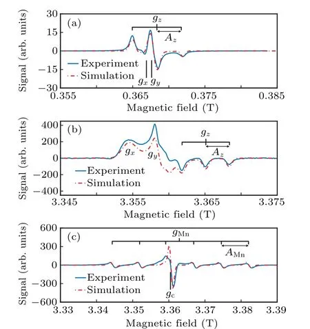
Fig.4. Experimental and simulated CW EPR spectra of starch at room temperature with modulation amplitude of 2 Gauss. Blue lines are experimental data and the red dashed lines are the simulations. (a)The X-band EPR spectrum of starch. The frequency of the microwave is 9.82 GHz and the power is 1.0 mW. The modulation frequency is 100 kHz. (b) The W-band EPR spectrum of starch with a split-pair magnet. The mw frequency is 94.2 GHz with an input power of 0.63 mW. The modulation frequency is 6.25 kHz.(c) The W-band EPR spectrum of lignite with a solenoid-type magnet. The mw frequency is 94.1 GHz with an input power of 0.63 mW.The modulation frequency is 6.25 kHz.
The characteristic shape of the spectrum is due to the anisotropy ofgfactor and hyperfine splitting.[12]Thegzzpeak splits into three because of theAzzhyperfine-tensor component. They are corresponding to the three peaks observed in Fig.4(a). Thegxxandgyypeaks,which are hidden at X-band,are resolved clearly at W-band. Figure 4(c)shows the experimental result at W-band using the cavity with a solenoid-type magnet, when the sample is lignite powder. It is the combination of a singlet contributed from carbon atoms and a sextet contributed from Mn2+ions.[30]The power of the microwave is set to 0.6 mW and the frequency of the microwave is 94.1195 GHz. The frequency of the modulation field is 6.25 kHz,and the amplitude of the modulation field is 2 Gauss.Our experiments show that the cavity suits with both types of magnets.
4.3. Pulsed EPR experiment
For testing the performance of the cavity in pulsed experiments, Rabi oscillation and relaxation-time experiment are conducted with lignite. Pulsed EPR technology has a wide range of applications in fields such as quantum information.[31,32]It also helps to understand the spin–spin and spin–environment interactions, which are highly concerned in chemistry and biology.[33]Since Mn2+ions relax extremely fast, all the pulsed EPR signal can be attributed to carbon atoms.[34]
For Rabi oscillation experiment,the microwave pulse sequence is shown as the inset of Fig.5(a). The frequency of the microwave is 93.7343 GHz and the peak microwave power is 200 mW. The direction of the external fieldB0is defined asz-axis and that ofB1asy-axis. Firstly a pulse with durationτpis applied to rotate Bloch vectors of the spins around thex-axis in the frame that is rotating withB1. Bloch vectors rotate around the external field at Larmor frequencyωL=γeB0.Since the external field is not perfectly uniform, the vectors have slightly different angular speeds and diffuse when rotating. After a period of evolution timeτ0,aπpulse is applied so that the Bloch vectors rotate 180°around thex-axis and begin to refocus. After anotherτ0the effect of diffusion is almost canceled and the Bloch vectors gather in one place,forming a spin echo. Here we setτ0as 300 ns. As shown in Fig. 5(a),different lengths of the first pulse are corresponding to different polarizations,so the amplitude of the echo signal oscillates with the pulse length. The pulse length of theπ/2 (π) pulse is measured to be 42(85)ns. The amplitude of theB1field is 2.1 Gauss while the power of the microwave pulses is 200 mW.Thus the microwave-power-to-magnetic-field conversion factor is 4.7 Gauss/W1/2.
To measure the transverse(spin–spin)relaxation timeT2,we set the first mw pulse as theπ/2 pulse and vary the evolution timeτwin the Hahn echo sequence. Since the spins are not isolated but interact with each other, the Bloch vectors in thexy-plane continue to shorten,and as a result,the refocused spin echo exponentially decays over time. The echo signal can be fitted by

whereSis the signal intensity,T2is the spin-spin relaxation time,A1andA2are fitting constants. According to the experimental data shown in Fig.5(b),T2=248.3±4.0 ns.

Fig. 5. Pulsed EPR experiments with lignite. The inset in each subplot shows the pulse sequence for each experiment. The microwave has the frequency of 93.7343 GHz and input power of 200 mW.The pulse lengths of the π/2 pulse and π pulse are 42 and 85 ns,respectively. (a)The Rabi oscillation experiment. The duration of the first pulse τp is swept from 20 ns to 240 ns in the 4-ns step. The interval between two pulses τ0 is set to 300 ns.(b)Experimental data of measurement of the transverse relaxation time.The interval between two pulses τw varies in the 24-ns step with an initial value of 300 ns. The fitting gives T2=248.3±4.0 ns.
5. Conclusion
In summary, we have designed a new type of resonant cavity for W-band EPR. A novel, improved coupling mechanism is developed. The coupling strength can be adjusted from 0.2 to 17.9. The cavity is compatible with both types of magnets that are commonly used in EPR spectrometers. It is installed in a W-band EPR spectrometer and tested with two types of magnets.
The results of field-swept CW experiments show that our cavity suits with both types of magnets.By pulsed EPR experiments,it is demonstrated that the cavity is qualified for quantum state manipulation and dephaseing-time measurements.The microwave-power-to-magnetic-field conversion factor up to 4.7 Gauss/W1/2is also achieved.
Acknowledgements
Project supported by the Chinese Academy of Sciences(Grant Nos. XDC07000000 and GJJSTD20200001). X. R.thanks the Youth Innovation Promotion Association of Chinese Academy of Sciences for the support.
- Chinese Physics B的其它文章
- Photoreflectance system based on vacuum ultraviolet laser at 177.3 nm
- Topological photonic states in gyromagnetic photonic crystals:Physics,properties,and applications
- Structure of continuous matrix product operator for transverse field Ising model: An analytic and numerical study
- Riemann–Hilbert approach and N double-pole solutions for a nonlinear Schr¨odinger-type equation
- Diffusion dynamics in branched spherical structure
- Application of Galerkin spectral method for tearing mode instability