
Microwave absorption properties regulation and bandwidth formula of oriented Y2Fe17N3-δ@SiO2/PU composite synthesized by reduction–diffusion method
2022-11-21 09:40HaoWang王浩LiangQiao乔亮ZuYingZheng郑祖应HongBoHao郝宏波TaoWang王涛ZhengYang杨正andFaShenLi李发伸
Chinese Physics B 2022年11期
Hao Wang(王浩) Liang Qiao(乔亮) Zu-Ying Zheng(郑祖应) Hong-Bo Hao(郝宏波)Tao Wang(王涛) Zheng Yang(杨正) and Fa-Shen Li(李发伸)
1Institute of Applied Magnetism,Key Laboratory for Magnetism and Magnetic Materials of Ministry of Education,Lanzhou University,Lanzhou 730000,China
2State Key Laboratory of Baiyunobo Rare Earth Resource Researches and Comprehensive Utilization,Baotou 014000,China
As concepts closely related to microwave absorption properties,impedance matching and phase matching were rarely combined with material parameters to regulate properties and explore related mechanisms.In this work,reduction–diffusion method was innovatively applied to synthesize rare earth alloy Y2Fe17. In order to regulate the electromagnetic parameters of absorbers,the Y2Fe17N3-δ particles were coated with silica(Y2Fe17N3-δ@SiO2)and absorbers with different volume fractions were prepared. The relationship between impedance matching, matching thickness, and the strongest reflection loss peak(RLmin)was presented obviously.Compared to the microwave absorption properties of Y2Fe17N3-δ/PU absorber,Y2Fe17N3-δ@SiO2/PU absorbers are more conducive to the realization of microwave absorption material standards which are thin thickness,light weight,strong absorbing intensity,and broad bandwidth.Based on microwave frequency bands,the microwave absorption properties of the absorbers were analyzed and the related parameters were listed. As an important parameter related to perfect matching, reflection factor (■εr/μr) was discussed combined with microwave amplitude attenuation. According to the origin and mathematical model of bandwidth,the formula of EAB(RL <-10 dB)was derived and simplified. The calculated bandwidths agreed well with experimental results.
Keywords: microwave absorption, rare earth alloy, reduction–diffusion method, Y2Fe17N3-δ@SiO2, reflection factor,impedance and phase matching,bandwidth formula
1. Introduction
In the present society, as an important carrier of information transmission,microwave is widely used in human life,production, and military equipment. However, owing to the rapid development of high frequency wireless communication technology and the application of various electronic devices, electromagnetic radiation interferes with the operation of electronic equipment and reduces the operation life increasing seriously.[1]In addition,the advancement of radar technology in different frequency bands also brings severe challenges to stealth military equipment. Therefore, the development of high-efficiency microwave absorption materials with properties including light weight, thin thickness, strong absorption strength, wide efficient microwave absorption materials has become an urgent demand.
In the past studies, researchers have tried a variety of materials. These microwave absorption materials can be mainly divided into dielectric-loss-type materials, magnetic materials.[2]Dielectric-loss materials are coal-based carbon,[3]biochar,[4]and conductivity polymers,etc.; magnetic materials are ferrites,[2]transition metals,[5]and metal alloy,[6]etc.In addition, the microwave absorption properties can be adjusted by changing morphology, size, and distribution of materials, like three-dimensional (3D) biological carbon,[4]layered structure,[6]carbon nanotubes,[7]nanospheres,[8]and hollow core–shell structure,[9]etc. The above factors provide various options and ideas for microwave absorption researches.
Now, in these last months of her pregnancy, the soft coral robe fit her perfectly47. She had found it packed away and had held it up to show him. But your sister died so long ago, she exclaimed, suddenly puzzled, and for an instant he had frozen, smiling, the lie from a year before darting48 like a dark bird through the room. Then he shrugged49, sheepish. / had to say something, he told her. I had to find a way to get your name. She smiled then, and crossed the room and embraced him.
In the past ten years,as magnetic material which has great potential in microwave absorption, rare earth alloy has been concerned and studied by researchers, microwave absorption properties of which are shown in Table 1. As one of the rare earth alloys,Y2Fe17N3-δhave potential in high frequency applications due to strong easy-plane anisotropy.[10]At present,the researches on Y2Fe17N3-δmainly focus on the field of high frequency soft magnetic composites (SMCs) and high frequency wave absorption.[10,11]On the one hand,as a magnetic material with similar property, Ce2Fe17N3-δprovides theoretical basis and practical data for high-frequency soft magnetic application of Y2Fe17N3-δ.[12]On the other hand,the exploration of Y2Fe17N3-δ’s microwave absorption property is still in the simple characterization stage of calculating reflection losses under given absorber thicknesses.[10]In addition,arc melting and a long homogeneous annealing were used to synthesize rare earth alloys in previous studies,which limits the production and complicates the process.[13,14]Therefore,it is urgent to explore and apply a new synthesis process to produce rare earth alloys efficiently in large quantities.
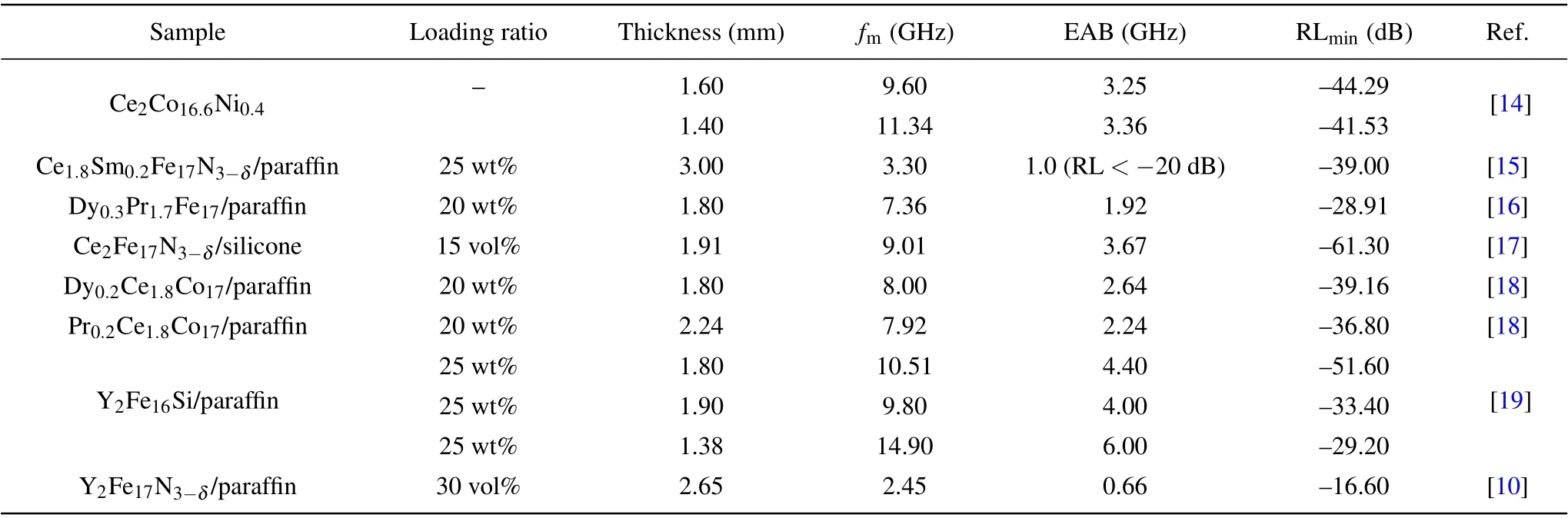
Table 1. Microwave absorption properties of different rare earth alloy composites.
As mentioned above,although the researchers have tried many materials and enumerated related data in detail to prove that their synthesized materials have excellent microwave absorption properties. However,these studies simply change the material parameters and calculate reflection losses (RL) by transmission line theory without exploring underlying mechanisms and considering frequency bands of application. As a result, microwave absorption materials have been made little progress in identifying microwave absorption mechanism and the realization of the goal of“thin thickness,light weight,wide bandwidth,strong absorbing intensity”.[5]From what has been discussed above,it is urgent to clarify the mechanisms of microwave absorption and unify the evaluation standards of microwave absorbing material in order to promote the research progress of microwave absorption.
For YFN/PU and YFN@Si/PU absorbers, according to Eqs. (2), (3), and (4), we can obtain impedance matching(|Zin/Z0|), matching thickness (tm,n=1) and the strongest reflection loss depended on frequency as shown in Fig.7. As shown in Figs.7(a)and 7(b),as the volume fraction increases,the best impedance matching frequency point (|Zin/Z0|=1)moves to the low frequency. At the same volume fraction,the best impedance matching frequency points of YFN@Si/PU absorbers are at higher frequencies. In addition, the best impedance matching frequency point of YFN@Si/PU absorber varies more regularly with the volume fraction, which is helpful to determine the best volume fraction of the absorber at a certain applied frequency. We also observed that too low volume fraction(15 vol%)cannot achieve the best impedance matching because the value of|Zin/Z0|is always larger than 1.
2. Experiment
2.1. Raw materials and synthesis
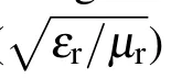
The raw materials of synthesizing Y2Fe17are Y2O3powder (purity 99.99%, 3 μm–5 μm), carbonyl iron powder(spherical, purity 99.9%, 3 μm–5 μm), and calcium (purity 99%, 3 mm). Based on the atomic ratio of Y2Fe17, an additional 50% of Y2O3powder was added to make up for the volatilization loss of Y in the reduction–diffusion process;On the basis of excess Y2O3, an additional 50% of the calcium was added to reduce Y2O3to Y fully. The raw materials were continuously mixed in argon atmosphere using a 3D mixing machine for 9 h. Finally,the mixture was pressed into a cylindrical shape under the pressure of 15 MPa and was moved to a tube furnace. The reduction–diffusion method was carried out in flowing Ar (200 mL/min). First of all, the temperature of the furnace needed to be raised and kept at 800°C–1100°C for 13 h. Then,the temperature was naturally cooled to room temperature in the atmosphere of flowing Ar. Finally, the alloy ingots after the reaction was broken to particles with size range at~50 μm by a jaw crusher.
The broken Y2Fe17N3-δparticles reacted reversibly with H2to make the particles smaller and then were moved into a high pressure reaction equipment. The high pressure nitriding process needed to be at 480°C under N2(purity 99.9999%)atmosphere of 10 MPa for 4 h. The particles after nitriding were cleaned and filtered with ammonium acetate solution(5 wt%)to remove CaO and excess Ca and then was cleaned with ethanol to remove water. Finally, the Y2Fe17N3-δparticles were obtained by drying in vacuum drying oven. The above synthesis process of Y2Fe17N3-δparticles and related process parameters were shown in Fig.1.Then,the Y2Fe17N3-δparticles were further broken with the size range at~5 μm through the planetary ball milling (250 r/min, 4 h) for the follow-up processes.
2.2. Coating process and absorber preparation
In order to change complex permeability and permittivity for regulating impedance matching, the silicon dioxide coating process was employed to synthesize Y2Fe17N3-δ@SiO2particles.[20]In this process,the stirrer kept rotating to ensure that materials were evenly dispersed in the solution. Firstly,5-g Y2Fe17N3-δ(~5 μm)particles were added and dispersed in 150-mL ethanol (99.7 wt%). Secondly, 2-mL 3-aminopropyl triethoxysilane (98 wt%) was added to the solution as a surfactant and the liquid–air interface became milky white after stirring 10 minutes.Then,40-mL deionized water,20-mL ammonia solution (25 wt%–28 wt%), and 3-mL tetraethyl silicate(98 wt%)were added to the solution successively and the solution will continue to be stirred for 2 h at 180 r/min. Finally,Y2Fe17N3-δ@SiO2particles were successfully synthesized and collected after the washing and drying processes.
6 One night, as he was tossing about in bed, full of cares and worry, he sighed and said to his wife: What s to become of us? how are we to support our poor children, now that we have nothing more for ourselves? I ll tell you what, husband, answered the woman; early to-morrow morning we ll take the children out into the thickest part of the wood; there we shall light a fire for them and give them each a piece of bread; then we ll go on to our work and leave them alone
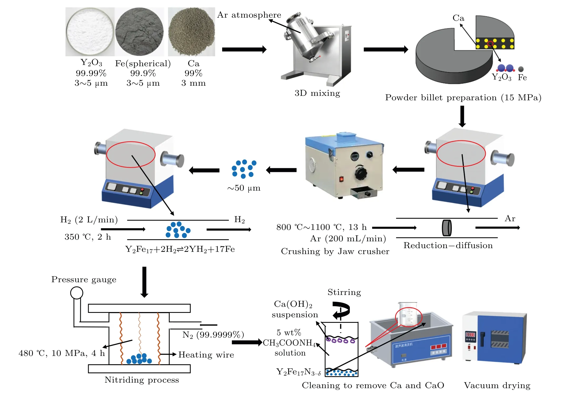
Fig.1. The synthesis process of Y2Fe17N3-δ particles.
2.3. Characterization
The crystal structures were characterized by x-ray diffraction (XRD, PANalytical X’ Pert PRO). The elemental differences between different samples were analyzed by x-ray photoelectron spectroscopy (XPS, Kratos AXIS Ultra DLD).The morphology was analyzed by scanning electron microscope (SEM, Apreo S). The distribution of elements in samples was analyzed by the energy dispersive spectrometer(EDS, EDAX). The vibrating sample magnetometer (VSM,Microsence EV9)was used to measure the hysteresis loops of samples. The complex permeability and complex permittivity of absorbers were obtained using a vector network analyzer(Agilent Technologies N5247A) in the range of 0.1 GHz–18 GHz range.
3. Results and discussion
3.1. Characterization of structure, micromorphology, element,and magnetic properties
whereMsis the saturation magnetization,Mr,out-of-planeis the remanence perpendicular to the plane of orientation.The oriented Y2Fe17N3-δ/PU composite has an excellent degree of plane orientation (DPO) 98.77% which further indicates that it is easy-plane microwave absorbing material.[11]Based on previous work about oriented microwave absorbers,the oriented composite absorber showed a dramatic increase in permeability and a remarkable decrease in the matching thickness.[13]In Fig. 4(c), the difference of hysteresis loops of Y2Fe17N3-δ(broken) and Y2Fe17N3-δ@SiO2particles is shown. TheMsof Y2Fe17N3-δ@SiO2particles decreases from 1060.6 emu/cm3to 944.3 emu/cm3because SiO2cannot be magnetized and occupies a certain volume. In addition, compared to the raw Y2Fe17N3-δparticles, theHcof Y2Fe17N3-δand Y2Fe17N3-δ@SiO2particles increases from 57.8 Oe to 125.5 Oe because stress is generated in particles during ball milling process.
In Fig. 2(d), the loose, porous, and irregular structure and size (~50 μm) of raw Y2Fe17N3-δparticles can be clearly and intuitively observed and the formation of this structure is due to the diffusion of Ca and the volatilization of Y during the synthesis process. The scanning electron microscopy(SEM)images exhibit the microscopic morphologies of Y2Fe17N3-δ(broken)and Y2Fe17N3-δ@SiO2particles as displayed in Figs. 2(e) and 2(f). As shown in Fig. 2(e), the Y2Fe17N3-δ(broken) particles display irregular shapes and the average size of~5 μm. In addition, as displayed in Fig.2(f)and Fig.3,Y2Fe17N3-δ@SiO2particles are covered tightly by nano-sized SiO2and agglomerated spherical silica attach to the surface of particles. In order to further characterize the distribution of elements after coating,the elemental mapping images of Y2Fe17N3-δ@SiO2particles are shown in Fig. 3. From the elemental mapping images, we can see that the element distribution is highly consistent with the shapes of Y2Fe17N3-δ@SiO2particles which indicates SiO2coats the surface of particles tightly and evenly.
Fig. 2. (a) XRD pattern of raw Y2Fe17N3-δ particles. (b) XRD patterns of Y2Fe17N3-δ (broken) and Y2Fe17N3-δ@SiO2 particles. (c) XPS of Y2Fe17N3-δ (broken) and Y2Fe17N3-δ@SiO2 particles. (d)–(f) SEM images of raw Y2Fe17N3-δ, Y2Fe17N3-δ (broken), and Y2Fe17N3-δ@SiO2 particles.
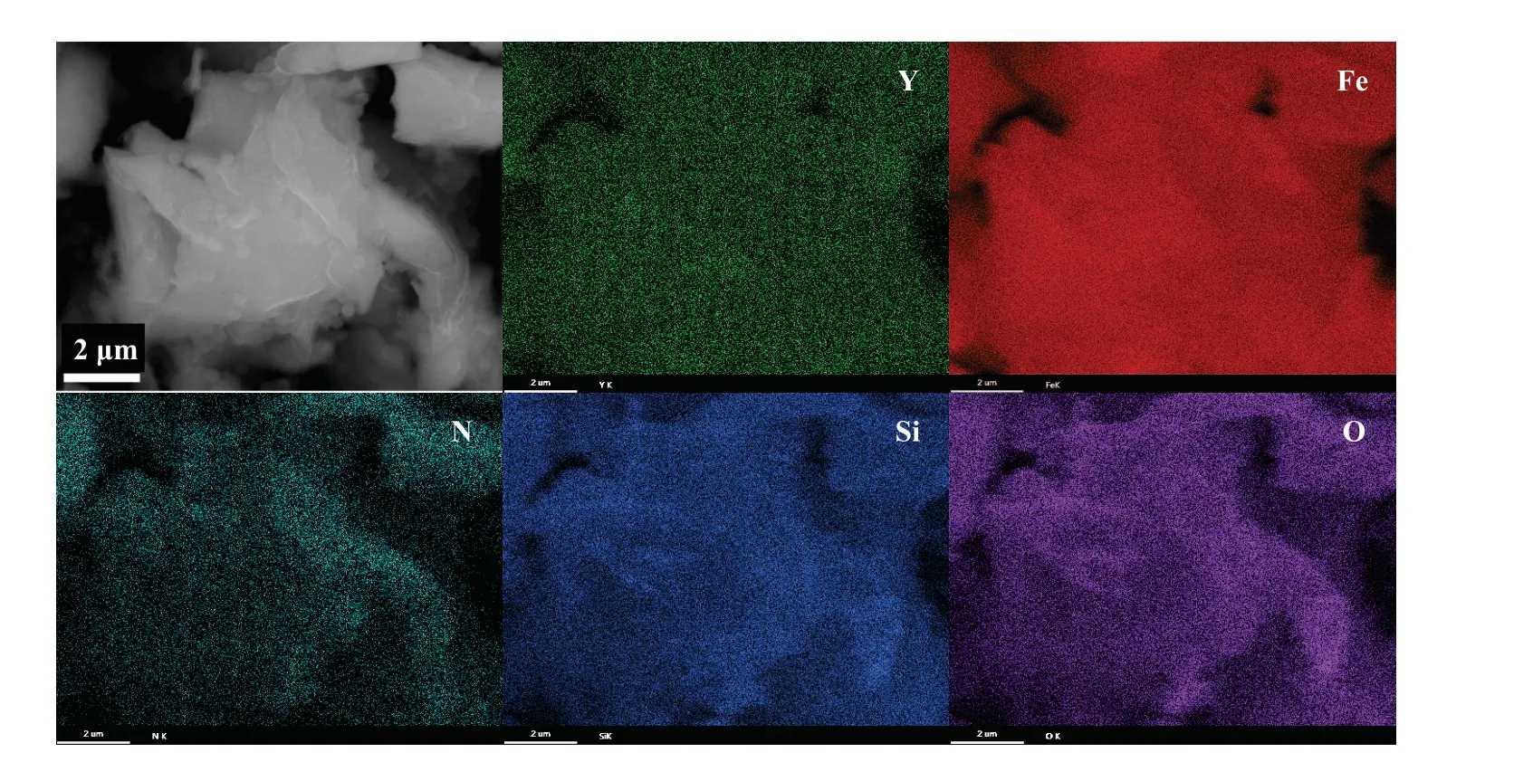
Fig.3. The SEM image and elemental mapping images of Y2Fe17N3-δ@SiO2 particles.
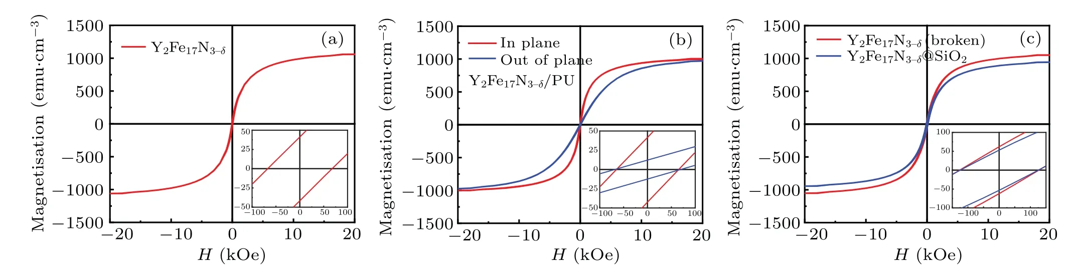
Fig. 4. (a) The hysteresis loop of raw Y2Fe17N3-δ particles. (b) The hysteresis loops in-plane and out-of-plane directions of oriented Y2Fe17N3-δ/PU composite. (c)The hysteresis loops of Y2Fe17N3-δ (broken)and Y2Fe17N3-δ@SiO2 particles.
The complex permeability (μr=μ′-jμ′′) and complex permittivity(εr=ε′-jε′′)of YFN/PU and YFN@Si/PU absorbers are measured by coaxial method at room temperature over 0.1 GHz–18 GHz and are shown in Fig. 5. Obviously,on the one hand,the values of complex permeability and permittivity are positively correlated with the volume fraction.On the other hand,under the same volume fraction,the complex permeability and complex permittivity of YFN@Si/PU absorbers decrease significantly relative to YFN/PU absorbers which is majorly due to the introduction of non-magnetic silica particles and the decrease of electrical conductivity after silica coating. In addition, comparing with YFN/PU absorbers, the resonance peaks of YFN@Si/PU absorbers still in relaxation mode do not change significantly.
“Now I must hasten away to warmer countries,” said the Snow Queen. “I will go and look into the black craters6 of the tops of the burning mountains, Etna and Vesuvius, as they are called,—I shall make them look white, which will be good for them, and for the lemons and the grapes.” And away flew the Snow Queen, leaving little Kay quite alone in the great hall which was so many miles in length; so he sat and looked at his pieces of ice, and was thinking so deeply, and sat so still, that any one might have supposed he was frozen.
The girl said what she had said on each of the former occasions -- that it was not for sale either for gold or for money, but if she could get leave to go to the Prince who lived there, and be with him during the night, she should have it
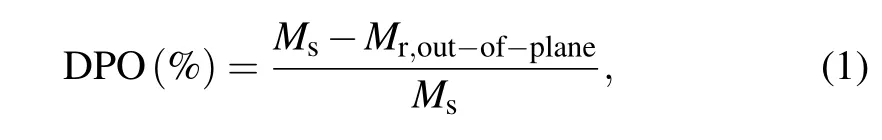
Figure 2(a) shows the XRD pattern of raw Y2Fe17N3-δparticles. As shown in Fig. 2(a), the XRD pattern is completely consistent with PDF#86-0450 which is the standard card of Y2Fe17N2.4. It is worth noting that the content ofα-Fe precipitated from Y2Fe17N3-δis extremely low comparing with the previous work aboutRe2Fe17N3-δ(Re=rare earth elements).[2,10,19]This result shows that high pressure nitriding technology is a promising process for the preparation of pure Re2Fe17N3-δ. In Fig. 2(b), compared to Y2Fe17N3-δ(broken) particles, the XRD pattern of Y2Fe17N3-δ@SiO2particles do not change significantly and the intensity of its diffraction peaks drop slightly. Therefore, the crystal structure of Y2Fe17N3-δ@SiO2particles has not been changed during the coating progress. As shown in Fig. 2(c),compared to Y2Fe17N3-δ(broken) particles, the XPS of Y2Fe17N3-δ@SiO2particles have obvious intensity peaks at 100 eV and 551 eV respectively. These peaks and the XPS peaks of Si and O are at the same position which indicates that the Y2Fe17N3-δ@SiO2is composed of Y2Fe17N3-δand silica.
So be it, said the Wolf and beat his paw against the dry ground, and immediately he took the shape of the Horse with the Golden Mane, so like to that the Princess rode that no one could have told one from the other. Then Tsarevitch Ivan, leaving Helen the Beautiful on the green lawn with the real Horse with the Golden Mane, mounted arid39 rode to the Palace gate.
3.2. Impedance matching and microwave absorption properties of YFN/PU and YFN@Si/PU absorbers
The hysteresis loop of raw Y2Fe17N3-δparticles is shown in Fig. 4(a). As we can see, the coercivity (Hc) and the saturation magnetization (Ms) of raw Y2Fe17N3-δparticles are 57.8 Oe(1 Oe=79.5775 A·m-1)and 1060.6 emu/cm3respectively. According to previous studies,the Curie temperature(TC)is increased from 325 K to 694 K due to nitriding,which raised the microwave absorption application temperature of Y2Fe17N3-δ.[21,22]In the direction parallel and perpendicular to the plane of orientation, the hysteresis loops of oriented Y2Fe17N3-δ/PU composite are shown in Fig. 4(b).The expression of DPO is as follows:
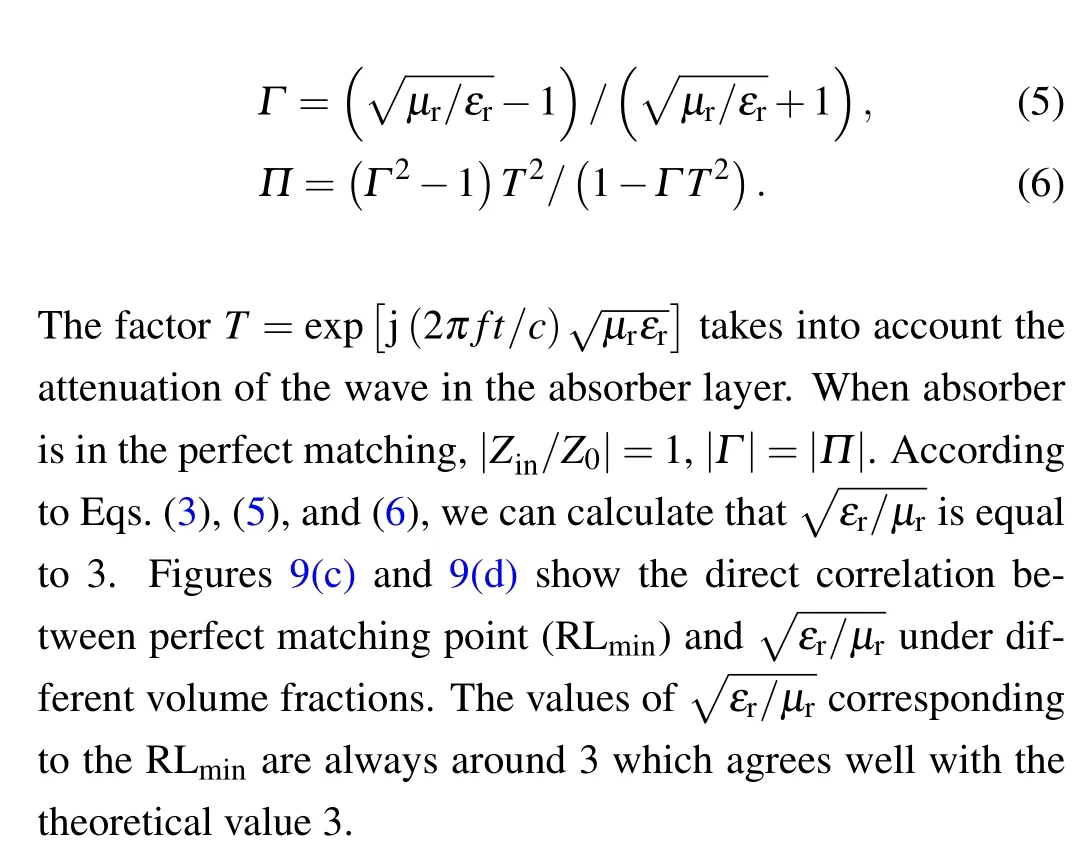
The previous work on microwave absorption shows that the excellent property of absorber depends on two key factors which are phase matching and amplitude matching respectively. On the one hand,according to interfacial reflection model, the thickness and applied frequency of absorber must satisfy the theory ofλ/4 interference cancellation for phase matching(phase difference =π).[2,23]The schematic diagram of interfacial reflection model andλ/4 interference cancelation theory is shown in Fig. 6. On the other hand, according to the matching theory in free space,the amplitudes of reflection waves are equal (|Γ|=|Π|) when impedance matching|Zin/Z0| = 1.[2,24,25]Therefore, the strongest reflection loss(RLmin) can be obtained if the above two conditions are satisfied(perfect matching).
She asked if he had gone out of his mind, but he answered crossly, What is that to you? Do as you are bid, and to-morrow I will bring you some treasures
According to interface reflection model,λ/4 interference cancellation theory and transmission line theory, matching thickness (tm), input impedance (Zin), and the reflection loss(RL)of absorbers are calculated in the following equations:[13]
Before and after coating, the change of matching thickness(tm)with frequency is shown in Figs.7(c)and 7(d). Since coating reduces complex permeability and permittivity, thetmof YFN@Si/PU absorber increases slightly at the same frequency and volume fraction. However, owing to the increase of best matching frequency, the thicknesses of perfect matching of YFN@Si/PU absorbers greatly decrease eventually. Therefore,silicon dioxide coating is beneficial to reduce the matching thickness and realize the light weight of the absorber. Finally, combined with Figs. 7(a), 7(c), 7(e) or 7(b),7(d),7(f),we can obtain the perfect matching thicknesses and the strongest reflection loss of YFN@/PU and YFN@Si/PU absorbers under different volume fractions.
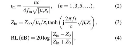
in whichfis the application frequency,cis the velocity of light in free space,tis the thickness of absorber,andZ0is the impedance of air.
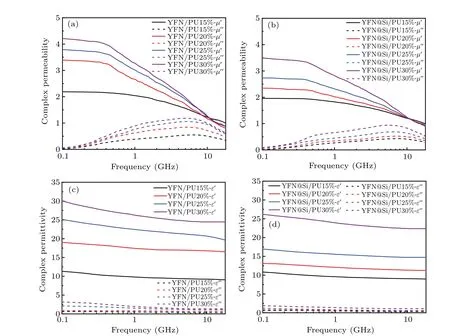
Fig. 5. (a)–(b) Complex permeability, (c)–(d) complex permittivity of YFN/PU and YFN@Si/PU absorbers depended on frequency under different volume fractions.
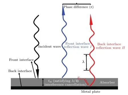
Fig.6. Schematic diagram of interface reflection model and λ/4 interference cancellation theory.
In vain did her husband represent to her their extreme poverty: she would not consent to it; she was indeed poor, but she was their mother. However, having considered what a grief it would be to her to see them perish with hunger, she at last consented,8 and went to bed all in tears.
With these words the beautiful Hyacinthia stamped on the ground with her little foot, and the earth opened and they both sank down into the lower world
For obtaining the complex permeability and complex permittivity,Y2Fe17N3-δ/PU and Y2Fe17N3-δ@SiO2/PU absorbers (YFN/PU and YFN@Si/PU) were prepared with different volume fractions (15 vol%, 20 vol%, 25 vol%,30 vol%). Firstly,the polyurethane(PU)was completely dissolved in acetone under continuous ultrasonic condition. Then Y2Fe17N3-δor Y2Fe17N3-δ@SiO2particles were added and dispersed in the solution fully. Finally, the liquid composed of alloy particles,polyurethane and acetone was orientated in a parallel rotating magnetic field (1 T) for 15 minutes until acetone volatilized completely. After the above processes,the orientated composite was made into a toroidal shape sample(φin=3.04 mm,φout=7.00 mm)using a mold.
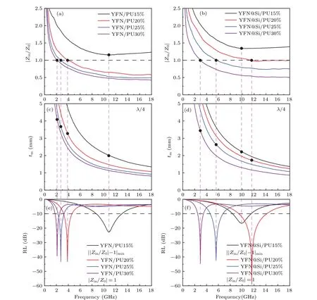
Fig. 7. (a)–(b) Impedance matching (|Zin/Z0|), (c)–(d) matching thickness (tm, n = 1), and (e), (f) the strongest reflection loss of YFN/PU and YFN@Si/PU absorbers depended on frequency under different volume fractions.
In practical application,it is meaningless to discuss only the value of reflection loss peak without considering the matching thickness,microwave absorption bandwidth,and applied frequency band. Therefore, in order to show the microwave absorption properties vividly, the RL of absorbers depended on thickness and frequency under different volume fractions is shown in the form of contour figures(color fill)as shown in Fig. 8. The contour lines of-10 dB and-20 dB are labeled which indicate that microwave energy absorption efficiencies of absorber are 90%and 99%respectively.
There are several starting points of the characterization of absorber’s property. From the point of perfect matching, the RLminand EAB of YFN/PU (20 vol%) absorber is-43.23 dB and 1.43 GHz respectively at 3.86 GHz with thickness of 3.29 mm; In contrast, the RLminvalue and EAB of YFN@Si/PU(20 vol%)absorber is-59.02 dB and 4.74 GHz respectively at 11.60 GHz with thickness of 1.70 mm. The above data shows that YFN@Si/PU absorbers are more conducive to the realization of microwave absorption material standards which are thin thickness, light weight, strong absorbing intensity, and broad bandwidth. From the point of EAB covering given frequency bands, in order to illustrate the microwave absorption properties of absorbers in X-band(8 GHz–12 GHz)and Ku-band(12 GHz–18 GHz),the related parameters are shown in Figs. 8(c), 8(d), 8(f), and Table 2.Therefore,it is necessary to choose between RL and the coverage frequency band of EAB in absorber’s design.
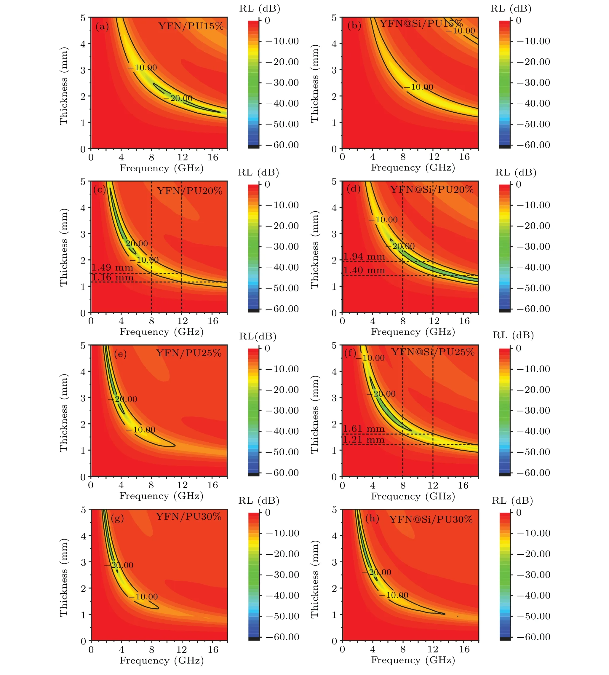
Fig.8. The reflection loss of YFN/PU and YFN@Si/PU absorbers depended on thickness and frequency under different volume fractions.

Table 2. The parameters related to microwave absorption properties of YFN/PU(20 vol%)and YFN@Si/PU(20 vol%,25 vol%)absorbers.
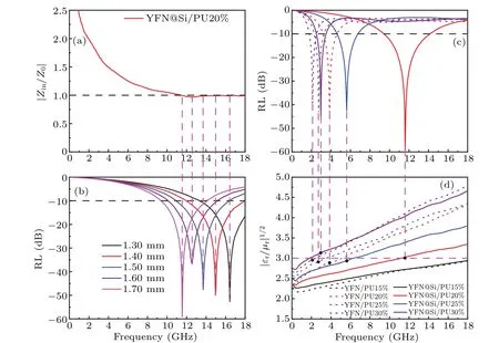
Fig. 9. (a) The |Zin/Z0|–f curv■e and (b) RL of YFN@Si/PU (20 vol%) absorber vary between 11.60 GHz–18 GHz at different thicknesses. (c) The RLmin and(d)reflection factor(of YFN/PU and YFN@Si/PU absorbers depended on frequency under different volume fractions.
3.3. Influencing factors and bandwidth formula of effective absorption bandwidth(EAB:RL <-10 dB)
In the previous work,as the main parameter of microwave absorption property, effective absorption bandwidth has been concerned and studied. As the RL peak comes from the cancelation of the front interface reflection wave (Γ) and back interface reflection wave(Π),their phase difference should beπat the peak frequency point. When the frequency deviates from the peak frequency point by Δf, the peak intensity will decrease due to that the phase difference of the two reflected waves deviates fromπtoπ-θorπ+θ.[23,27]Figure 10 is a schematic analysis of the microwave absorption bandwidth based on the origin of bandwidth and mathematical model. As shown in Figs. 10(a), 10(c), and 10(d), Δfis the half bandwidth at-10 dB,RL1is the reflection loss at a specified point,RL0is the reflection loss at the peak frequency point,Ais the amplitude of the reflection wave (A=|Γ+Π|). Starting from microwave amplitude,the derivation process of effective bandwidth formula is shown as follows taking YFN@Si/PU(25 vol%)absorber for example.
As shown in Figs. 10(a) and 10(b), when the reflection losses are RL0and RL1respectively,the amplitudes of reflection wave areA0andA1respectively which can be written as

Assuming thatθis small enough,it can be described by Taylor expansion recursion formula
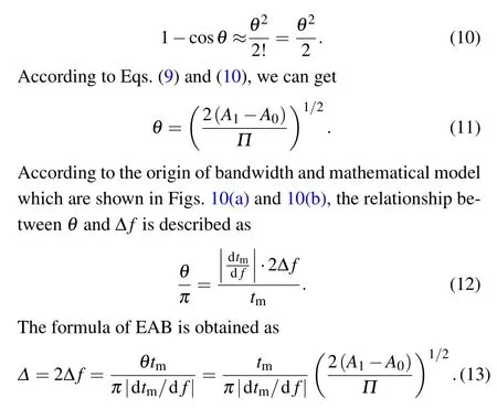
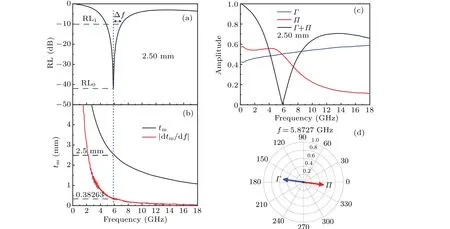
Fig. 10. (a) The RL–f, (b) tm–f and |dtm/d f|–f curves. (c) Γ, Π, and Γ +Π vary with frequency. (d) The vector pole figure of Γ and Π at 5.8726 GHz for YFN@Si/PU(25 vol%)absorber with thickness of 2.50 mm.
When absorber is in perfect matching and enough complex permeability and permittivity data points are measured,RL0=-∞,A1=10-(10/20)=0.3162,A0=10(-∞/20)≈0. Finally,the formula of EAB can be expressed by
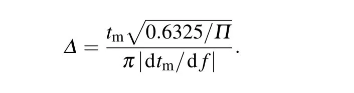
Equation (13) demonstrates that EAB is mostly influenced by the thickness, the derivation of matching thickness to frequency and the amplitude of the front interface reflection wave. In the above factors, bandwidth is most sensitive to the|dtm/df|. According to Eq. (13), the related parameters of the calculated and experimental bandwidth are listed under various thicknesses as shown in Table 3. Obviously,the bandwidths from the theoretical calculations under various thicknesses agree well with those of the experimental results.
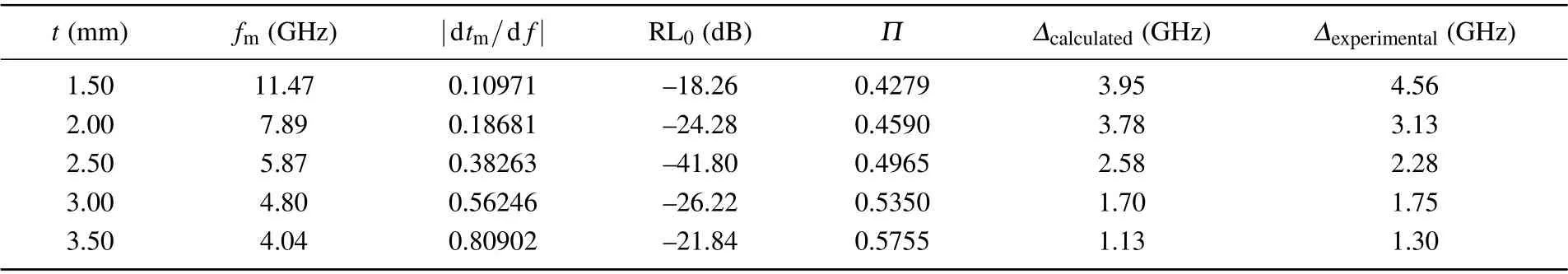
Table 3. The parameters of the calculated and experimental bandwidth(RL <-10 dB)for YFN@Si/PU(25 vol%)absorber under various thicknesses.
4. Conclusion
Acknowledgements
Project supported by the National Key Research and Development Program of China(Grant No.2021YFB3501300),the National Natural Science Foundation of China (Grant No. 51731001), and the Fund from the State Key Laboratory of Baiyunobo Rare Earth Resource Researches and Comprehensive Utilization’s Key Research and Development Projects.
猜你喜欢
走向世界(2022年18期)2022-05-17
理科爱好者(教育教学版)(2022年2期)2022-05-05
Plasma Science and Technology(2022年2期)2022-03-10
少儿美术·书法版(2021年7期)2021-10-20
大众文艺(2020年23期)2021-01-04
大众文艺(2020年22期)2020-12-13
作文大王·低年级(2018年5期)2018-06-20
作文大王·低年级(2018年4期)2018-05-24
故事林(2017年17期)2017-09-12
- Chinese Physics B的其它文章
- A design of resonant cavity with an improved coupling-adjusting mechanism for the W-band EPR spectrometer
- Photoreflectance system based on vacuum ultraviolet laser at 177.3 nm
- Topological photonic states in gyromagnetic photonic crystals:Physics,properties,and applications
- Structure of continuous matrix product operator for transverse field Ising model: An analytic and numerical study
- Riemann–Hilbert approach and N double-pole solutions for a nonlinear Schr¨odinger-type equation
- Diffusion dynamics in branched spherical structure