
Significant suppression of residual nitrogen incorporation in diamond film with a novel susceptor geometry employed in MPCVD
2022-11-21 09:30WeikangZhao赵伟康YanTeng滕妍KunTang汤琨ShunmingZhu朱顺明KaiYang杨凯JingjingDuan段晶晶YingmengHuang黄颖蒙ZiangChen陈子昂JiandongYe叶建东andShulinGu顾书林
Chinese Physics B 2022年11期
Weikang Zhao(赵伟康), Yan Teng(滕妍), Kun Tang(汤琨), Shunming Zhu(朱顺明),Kai Yang(杨凯), Jingjing Duan(段晶晶), Yingmeng Huang(黄颖蒙),Ziang Chen(陈子昂), Jiandong Ye(叶建东), and Shulin Gu(顾书林)
School of Electronic Science&Engineering,Nanjing University,Nanjing 210046,China
This work proposed to change the structure of the sample susceptor of the microwave plasma chemical vapor deposition(MPCVD)reaction chamber,that is,to introduce a small hole in the center of the susceptor to study its suppression effect on the incorporation of residual nitrogen in the MPCVD diamond film. By using COMSOL multiphysics software simulation,the plasma characteristics and the concentration of chemical reactants in the cylindrical cavity of MPCVD system were studied, including electric field intensity, electron number density, electron temperature, the concentrations of atomic hydrogen,methyl,and nitrogenous substances,etc. After introducing a small hole in the center of the molybdenum support susceptor,we found that no significant changes were found in the center area of the plasma,but the electron state in the plasma changed greatly on the surface above the susceptor. The electron number density was reduced by about 40%,while the electron temperature was reduced by about 0.02 eV,and the concentration of atomic nitrogen was decreased by about an order of magnitude. Moreover,we found that if a specific lower microwave input power is used,and a susceptor structure without the small hole is introduced,the change results similar to those in the surface area of the susceptor will be obtained,but the spatial distribution of electromagnetic field and reactant concentration will be changed.
Keywords: plasma simulation, diamond, microwave plasma chemical vapor deposition (MPCVD), residual nitrogen
1. Introduction
There are many kinds of impurities in natural diamond and synthetic diamond, which have an important impact on various physical properties of diamond. In the chemical vapor deposition system,the presence of residual gas often pollutes the surface of the vacuum chamber, resulting in the incorporation of impurities in the growth process of the sample. Nitrogen is the most common impurity in the synthesis of CVD and HPHT diamond,and its existence affects the thermal conductivity of diamond and produces various optical centers responsible for absorption. As a deep level donor impurity, it has electrical activity and compensates for acceptor impurities such as boron.[1]If there is no special treatment,there will always be a certain amount of nitrogen doping in diamond samples. Many relevant reports have been given on the reasons for the existence of residual nitrogen. Michael N. R. Ashfordet al.reported nitrogen pollution caused by incompleted vacuum or air impurities in the source gas.[2]A.Tallaireet al.believed that the nitrogen impurities observed in the experiment come from the remnant of previous experiments,less than 1 ppm.[3]A.P.Bolshakovet al.pointed out that chamber leakage is the main source of nitrogen pollution in the system.[4]In the process of growing diamond films in microwave plasma chemical vapor deposition (MPCVD) system, even a small amount of nitrogen will have an important impact on the quality of diamond films. Therefore,the control of residual nitrogen doping in diamond is the focus of current research. Some researchers have proposed a variety of methods to suppress residual nitrogen doping in diamond films. T.Matsumotoet al.reduced the residual nitrogen content by introducing oxygen into the reaction process.[5]J.Achardet al.reported that using higher substrate temperature in the reaction process will help to suppress residual nitrogen.[6]S. V. Nistoret al.studied that increasing the hydrogen flow rate can effectively reduce the residual nitrogen content in diamond films.[7]
2. Simulation and theoretical methods
2.1. Simulation modeling
The bet-down coupling cavity used in the experiment in this article is approximately cylindrical as a whole. In order to appropriately simplify the simulation process, we use COMSOL software suitable for simulating a two-dimensional axisymmetric model to study the electric field and plasma discharge characteristic parameter distribution during gas ionization in the reaction chamber. The input microwave power used in the simulation process is 3.8 kW, the working pressure is 18 kPa,and the microwave frequency is 2.45 GHz. The flow rates of hydrogen, methane, and nitrogen are 500 sccm,20 sccm,and 1 sccm,respectively. During the growth process,pure hydrogen is firstly introduced into the reaction chamber,and plasma is formed under the excitation of the input microwave source.After reaching a steady state,methane and nitrogen are introduced. The plasma environment will enhance methane cracking, and the generated carbon atoms/ions will be deposited on the substrate and complete the diamond film growth.[16]
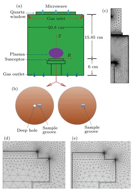
Fig.1. (a)The structure of MPCVD reaction chamber. (b)The top view of the susceptor with(left)/without(right)the small hole. (c)Two-dimensional grid model of the coupled waveguide and the discharge cavity. (d)The enlarged view of the susceptor area without the small hole. (e) The enlarged view of susceptor area with the small hole.
Figure 1 shows the simplified structure of the MPCVD reaction chamber and its two-dimensional axisymmetric grid model. Figure 1(a) shows the main structure of the MPCVD reaction chamber corresponding to our experimental equipment, HMPS-2050C microwave plasma CVD system. The plasma intensity is high and concentrated on the sample stage to avoid discharge in other areas of the cavity,which also improves the plasma stability and the quality of the deposited samples. Figure 1(b) compares the structural differences of the susceptor with (left) and without (right) the small hole.The diameter of the small hole is 2 mm and the square sample groove (side length 4 mm) is set 5 mm away from the center of the molybdenum support. Figures 1(c)–1(e)show the twodimensional axisymmetric grid model of coupling waveguide and discharge cavity in MPCVD system, as well as the enlarged grid view near molybdenum support, and the mesh is divided into free triangles.In order to optimize the accuracy of the simulation results,the rounded-corner structure is adopted at the edges of molybdenum susceptor and column support.
2.2. Electromagnetic field theory and reaction equations
All properties of the plasma domain excited by the microwave source are highly related to the electromagnetic field,and the electromagnetic field model used Maxwell’s equations and frequency domain-transient solver to solve the microwave field,

whereEis the electric field intensity vector,Bis the magnetic flux density,ρis the charge density,ε0is the vacuum permittivity,μ0is the vacuum permeability,Jis the conduction current density vector,andtis the time. The simulation structure of the reaction chamber is axisymmetric, so Maxwell’s equations are used to solve inrandzcoordinate space, and the origin of the space coordinates (r=0,z=0) is taken as the center point of the small hole on the surface of the susceptor.Due to the large number and complexity of chemical reactions involved in the diamond growth process,according to the main chemical reactions in the diamond growth process reported in relevant papers, we use COMSOL software to simplify the modeling and calculation. The main chemical substances and chemical reactions used are shown in Tables 1 and 2.

Table 1. Electron excitation and ionization reactions used in the calculation model of the reaction chamber.

Table 2.Surface reactions of heavy substances used in the calculation model of the reaction chamber.
The reactions with the symbol “↔” are regarded as reversible,and those with the symbol“→”are regarded as irreversible. The forward rate coefficientk=ATbexp(-E/RT),
where the units are cm3, K, kJ, mol and s, and the reverse rate coefficient is determined by the equilibrium constant.[15]Among them, H2s, CH4s and N2s are the corresponding excited states of the material,N2(A3)is the N2metastable state(the lowest energy triplet state),[12]and H+2, CH+4, N+2and CH+3are the corresponding material ion states.
3. Results and discussion
Figure 2(including the partial enlarged views)shows the comparison of the spatial distribution of the discharge characteristic parameters of the reaction chamber: with (down) and without (up) the small hole. It can be seen that the spatial distribution of the main parameters (including electron number density, electron temperature, electric field intensity and potential)are basically concentrated in the area above the surface of the susceptor, but there is no significant difference in the spatial distribution of discharge characteristic parameters between the two susceptor structure models.
In order to compare the discharge plasma characteristics of the two susceptor structures more clearly, we established aZ-axis cross-section line at the center of the sample growth groove (set the range of cross-section line coordinates: theRaxis is fixed at 5 mm, and theZaxis is from 0 to 15 cm), as shown in Fig. 3. We can see that the discharge characteristic parameters of the two models with and without the small hole in the susceptor differ slightly in spatial distribution. However,near the surface of the molybdenum support on the susceptor, for the model with/without small hole, such as electron number density, electron temperature values have obvious differences, which are 5.75×10¹³m-3/9.32×1013m-3,and 2.57 eV/2.59 eV, respectively. This means that after the susceptor in the reaction chamber is introduced into the small hole,the electron number density near the surface of the susceptor decreases by about 40% and the electron temperature decreases by 0.02 eV(about 230 K).
Since our research focus is on the change of reactant concentration distribution caused by the electromagnetic field near the surface of the susceptor, firstly, we use the threedimensional structure to more intuitively study the electric field distribution on the surface of the two susceptor. It can be seen that there is a certain difference between the two cases in the center of the susceptor, as shown in Fig. 4. Similar to theZ-axis two-dimensional cross-section line adopted above,we have established anR-axis two-dimensional cross-section line(set the range of cross-section line coordinates: theZaxis is fixed at 1.23 μm, which corresponds to the first data point in the spatial electromagnetic field distribution;and theRaxis is from 0 to 1.5 cm) to study the changes of electromagnetic field and the reactants concentration near the surface of the susceptor.
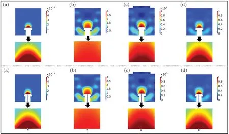
Fig. 2. The two-dimensional spatial distribution of the discharge characteristic parameters in the reaction chamber with (down) and without(up)the small hole and the partial enlarged view: (a)electron number density(1/m3);(b)electron temperature(eV);(c)electric field intensity(V/m);and(d)potential(V).

Fig.3. Distribution of discharge characteristic parameters in Z-axis direction in two-dimensional space of MPCVD reaction chamber models with and without the small hole: (a)electron number density;(b)electron temperature;(c)electric field intensity;and(d)potential.

Fig.4. Three dimensional electric field distribution on the surface of the susceptor: (a)without the small hole;(b)with the small hole.

Fig.5. Discharge characteristic parameters and concentration distribution of main reactants near the surface of the susceptor of MPCVD reaction chamber with and without the small hole: (a)electron number density;(b)electron temperature;(c)atomic hydrogen molar concentration;and(d)methyl molar concentration.
Figure 5 shows the distribution of the electronic state and the concentration of main reactants near the surface of the susceptor of MPCVD reaction chamber with and without the small hole. It can be seen that in the area where the small hole is introduced,the values of these characteristic parameters will increase first and then decrease rapidly, while in the central area near the surface of the susceptor,the distribution of them is relatively uniform. As can be seen from Figs.5(a)and 5(b),after the introduction of the small hole, the electron number density and electron temperature near the surface of the susceptor are reduced by about 40% and 0.02 eV, respectively.Figure 5(c) is a comparison of the distribution of atomic hydrogen concentration in the region of the surface of two susceptor structures. In the area near the center of the surface of the susceptor, after introducing the small hole, the atomic hydrogen concentration increased slightly. Because the currently generally accepted hydrogen desorption mechanism is that hydrogen atoms in the gas phase and atoms on the diamond surface form hydrogen molecules,[9]we believe that the decrease of electron temperature and density reduces the conversion of hydrogen atoms to hydrogen molecules,which will cause a decrease in hydrogen desorption. Figure 5(d) shows that the introduction of the small hole reduced the electron number density and electron temperature,resulting in a slight decrease in methyl concentration.
In order to study the change of nitrogen concentration in the small hole introduced into the susceptor, we adopted and simplified the reaction model of nitrogenous substances reported by Truscott B Set al.[12,20]The comparison of concentration changes of nitrogenous substances in the surface area of the susceptor is shown in Fig. 6. After the small hole is introduced into the susceptor,the concentrations of N and NH are reduced,especially the molar concentration of N decreases from 3.04×10⁻⁷mol/m3to 7.59×10⁻⁸mol/m3,that is,it decreased by an order of magnitude,and the molar concentration of NH is reduced by about 10%. These mean that the introduction of the small hole can effectively suppress the doping of residual nitrogen into the diamond film.

Fig. 6. The concentration distribution of nitrogenous substances near the surface of the susceptor of MPCVD reaction chamber with and without the small hole: (a) atomic nitrogen molar concentration; (b)NH molar concentration.
At the same time, corresponding to the relevant experiments in this paper,the electronic states and the concentration of nitrogenous substances in MPCVD reaction chamber are compared by using different microwave input power and reaction chamber structure, that is, reducing the microwave input power(2.9 kW)corresponds to the case that there is no small hole in the susceptor of the reaction chamber(defined as Condition 1),which is compared with the case with the small hole corresponding to the microwave input power of 3.8 kW used in the above content of this paper(defined as Condition 2),as shown in Figs.7 and 8. Figure 7 is a comparison of the electronic state results of the two simulation conditions. It can be seen that there are obvious differences in the spatial distribution of electron number density under the two conditions,and Condition 2 corresponds to a higher density of spatial electron distribution.

Fig. 7. Two dimensional spatial distribution and partial enlargement view of electron number density corresponding to different reaction chamber structures and microwave input power:(a)with the small hole-3.8 kW;(b)without the small hole-2.9 kW.
Figures 8(a) and 8(b) show the electronic state and nitrogenous substances concentration near the surface of the susceptor under the two simulated conditions. The electron number density and electron temperature also increased rapidly near the area of the small hole, and then decreased gradually in the central area of the susceptor away from the small hole.Most importantly, there is little difference between the electron number density and electron temperature under the two simulation conditions. While we used the above two simulation conditions to study and compare the changes of N and NH concentrations,as shown in Figs.8(c)and 8(d). As can be seen from Fig. 8(c), the N concentrations under the two simulation conditions are 7.58×10⁻⁸mol/m3(Condition 1) and 7.59×10⁻⁸mol/m3(Condition 2), and we can say that the difference between the two is very small; while the NH concentration difference between the two simulation conditions shown in Fig. 8(d) is even smaller. This seems to mean that the effect of the susceptor with the small hole on the growth state of diamond is equivalent to using a susceptor without the small hole and using lower input power (2.9 kW), but it will also change the spatial state distribution of electromagnetic field in the reaction chamber.

Fig.8. The distributions of electron number density and nitrogenous substances concentration near the surface of the susceptor corresponding to different reaction chamber structures and microwave input power: (a)electron number density;(b)electron temperature;(c)atomic nitrogen molar concentration;and(d)NH molar concentration.
4. Conclusion
In summary, we have used the COMSOL multiphysics software to study the plasma properties and substances concentration changes after the molybdenum support susceptor was introduced into the small hole in the MPCVD reaction chamber. The results show that after the small hole are introduced into the growth susceptor of the MPCVD reaction chamber, the electron number density and electron temperature near the surface of the susceptor of the reaction chamber decreased significantly;while the N concentration and NH concentration decreased, which will reduce the nitrogen doping efficiency in the diamond film and cause the growth rate of the film decreases (this corresponds to a decrease in electron temperature and density). It is generally believed that during the diamond growth process, high-energy electrons have an important influence on the hydrogen desorption on the diamond surface,[17–20]and changes in electron temperature and density have a great influence on the hydrogen coverage of the growth surface. We believed that the decrease of electron temperature and density reduced the conversion of hydrogen atoms to hydrogen molecules,which caused a decrease in hydrogen desorption, then the growth-limiting kinetics changed from mass transport to surface kinetics. In this case, the nitrogenous substance formed at the center of the plasma is not easy to be incorporated into the diamond surface due to the high hydrogen surface coverage.
Acknowledgements
The authors acknowledged financial support from the National Natural Science Foundation of China (Grant Nos.61974059,61674077,and 61774081)and the Fundamental Research Funds for the Central Universities,China.
猜你喜欢
疯狂英语·新悦读(2021年5期)2021-06-08
少儿科技(2021年5期)2021-01-20
歌海(2020年5期)2020-11-16
——江苏邳州老年大学校歌
老年教育(老年大学)(2020年10期)2020-10-22
作文评点报·低幼版(2020年32期)2020-07-23
商周刊(2019年18期)2019-10-12
青年生活(2019年3期)2019-09-10
老友(2019年1期)2019-01-30
故事作文·低年级(2018年1期)2018-01-16
学生之友·最作文(2017年11期)2018-01-11

- Chinese Physics B的其它文章
- A design of resonant cavity with an improved coupling-adjusting mechanism for the W-band EPR spectrometer
- Photoreflectance system based on vacuum ultraviolet laser at 177.3 nm
- Topological photonic states in gyromagnetic photonic crystals:Physics,properties,and applications
- Structure of continuous matrix product operator for transverse field Ising model: An analytic and numerical study
- Riemann–Hilbert approach and N double-pole solutions for a nonlinear Schr¨odinger-type equation
- Diffusion dynamics in branched spherical structure