
Enhanced and tunable circular dichroism in the visible waveband by coupling of the waveguide mode and local surface plasmon resonances in double-layer asymmetric metal grating
2022-11-21 09:30LiuLiWang王刘丽YangGu顾阳YiJingChen陈怡静YaXianNi倪亚贤andWenDong董雯
Chinese Physics B 2022年11期
Liu-Li Wang(王刘丽) Yang Gu(顾阳) Yi-Jing Chen(陈怡静) Ya-Xian Ni(倪亚贤) and Wen Dong(董雯)
1School of Physical Science and Technology,Soochow University,Suzhou 215006,China
2Soochow College,Soochow University,Suzhou 215006,China
Circular dichroism(CD)has shown very interesting possibilities as a means to characterize the chiral signal of a chiral structure. Here, we theoretically demonstrated enhanced and tunable CD in the visible light regime using a composite structure consisting of a double-layer metal grating gaped by a dielectric waveguide layer. Based on the coupling of the waveguide modes and the localized plasmonic resonances, the CD could reach a maximum value as high as 0.52 at 635 nm,which is four times higher than the CD value obtained in a conventional double-layer grating without the waveguide coupling effect. Furthermore, the spectral positions of the enhanced CD bands could be easily tuned by controlling the structural parameters. The proposed hybrid double-grating and waveguide structures could have potential applications in chiral selective imaging,sensing and spectroscopy,especially where the transmission measurement is required.
Keywords: circular dichroism,chiral metamaterial,waveguide,surface plasmon
1. Introduction
Chirality refers to the characteristic in that the mirror image of a structure cannot coincide with itself, which is a geometric description of structural symmetry.[1]Since Pasteur first proved the existence of chiral molecules,it has been found that chiral phenomena are common in nature, such as DNA and proteins.[2]In recent years,the different characteristics of chiral structures in asymmetric electromagnetic fields have attracted extensive attention.[3–6]From the classical electromagnetic point of view,chiral structures show different optical responses under the irradiation of left-handed circularly polarized light (LCP) and right-handed circularly polarized light(RCP), and the different optical coefficients lead to circular dichroism(CD).As one of the means used to characterize the asymmetric optical response of chiral structures,CD is widely used in chiral molecular detection,nonlinear imaging,and chiral catalysis.[7–9]
Usually, the CD response of natural chiral materials is very weak, which makes it difficult to detect.[10]To solve this problem,researchers combined metal metastructures with chiral materials, where the local field enhancement associated with the excitation of plasmonic resonances was employed to effectively enhance the chiral optical response of chiral materials.[11–14]It is worth noting that the CD signals of most biomolecules are in the ultraviolet region;if the plasmonic resonance frequency of a metal metastructure is in the visible region, its interaction is still weak.[15–17]Therefore,for biomolecules with CD bands in the UV region, the plasmonic resonance frequency could be adjusted in the ultraviolet region,[18]which provides a possible way to enhance CD in the ultraviolet band.
Meanwhile,chiral surface plasmon structures with strong CD signals have attracted great attention.[19–22]Compared with chiral molecules in nature,the CD signal of a chiral surface plasmon structure could be several orders of magnitude stronger and easier to manipulate. For example,based on engineered CD signals and the hot electron transfer process in plasmonic nanostructures,Valentineet al.designed a light detector with the ability to directly distinguish left-hand from righthand circularly polarized light.[20]Unlike the traditional circularly polarized photodetector that requires additional optical elements,chiral plasmon based circularly polarized photodetectors are simpler and more compact, and thus suitable for use in integrated optical devices.[23]Moreover, the resonance frequency of surface plasmons strongly depends on the shape, size, material and surrounding dielectric medium,which provides an efficient way to tune the operation bands of the CD signals. Although relatively strong gap-plasmon based CD responses have been achieved in plasmonic nanostructures consisting of zigzag nanowires and a metal backplane separated by a dielectric spacer,[20,22]such types of chiral plasmonic structures could only operate in the reflectance mode due to the existence of the thick metal layer. Double-layer gold crossed gratings have been demonstrated to exhibit CD responses in the transmission.[19]However, its generated CD is still weak and further enhancement of the transmittance CD remains a challenge.
In this paper, we investigated the CD response from hybrid chiral plasmonic nanostructures,which consist of doublelayer gold crossed gratings separated by a waveguide layer,in the visible light region. We demonstrated that the CD in the transmittance could be greatly enhanced with the aid of the coupling between the chiral plasmon resonances and the waveguide modes. Compared with conventional double-layer gold gratings without the waveguide coupling effect,the maximum CD of the proposed hybrid plasmonic nanostructures could be improved more than 4 times. We also demonstrated that by varying the period of the gratings or the thickness of the waveguide layer, the enhanced CD band could be easily tuned in the visible light region.
2. Structure and simulations
Figure 1(a) schematically shows the hybrid chiral plasmon nanostructure. The top and bottom gold (Au) gratings are separated by a layer of Al2O3. As will be demonstrated later,the thickness of the Al2O3layer could be used to control whether or not the waveguide mode could be excited. Figure 1(b) shows the top view of the unit cell of the structure.The light is incident along the-zaxis. If we look along the+zaxis, the top grating rotates anticlockwise with respect to the bottom grating. The anticlockwise rotation angleθwithin the range of (0°, 90°) corresponds to the right-handed (RH)chiral structure, while the rotation angle within the range of(90°, 180°) corresponds to the left-handed (LH) chiral structure.

Fig. 1. (a) Schematic of the chiral plasmon structure, which consists of the double-layer gold(Au)nanogratings periodically arranged on glass substrate, separated by a thin Al2O3 spacer layer. The illustration in this figure corresponds to the right-handed structure. (b) A top view of one periodic unit in the structure. It can be seen that the top layer Au nanogratings makes a cross-angle θ with the bottom layer Au grating.ttop=tbot=30 nm,Wtop=Wbot=110 nm,hwg=250 nm,θ =45°.
To investigate the optical response and physical mechanism of the hybrid double-layer grating and waveguide structures, numerical simulations were conducted using the threedimensional finite-element method(FEM)software COMSOL Multiphysics. In the calculations, four sides along the orientation of the two gratings of the unit cell were applied with periodic boundary conditions, and its top and bottom boundaries were terminated with perfectly matched layers to absorb the reflected and transmitted light in thez-direction. The circularly polarized light(CPL)was assumed to be normally incident on the nanostructures. The CPL could be regarded as the coupling of two linearly polarized lights with a phase difference of 90°, and field vectors of the right-handed circular polarization (RCP) and the left-handed circular polarization(LCP)could then be written as

The transmission coefficient of the CPL is also obtained by the superposition of transmission polarized light. Therefore, the total transmittance of the structure (TRfor RCP andTLfor LCP) can be calculated using the cross- and copolarized transmission coefficient under RCP light and LCP light:TR=|t++|2+|t-+|2andTL=|t--|2+|t+-|2. For the transmission coefficient(t),the two subscriptst+/-denote the transmitted and incident waves,respectively. For light propagating along the-zdirection,the subscript+donates the RCP light and-donates the LCP light. Finally,CD can be calculated using the definition of CD=TR-TL.In the calculations,the dielectric constants of Au are taken from the experimental data,[24]and the refractive indexes of Al2O3and glass are assumed to be 1.7 and 1.459, respectively. Thettop,tbot, andWtop,Wbotare represented as the thickness and linewidth of the top and bottom grating,respectively. Details of the model and calculation settings can be found in the supporting information(Fig.S1).

wheremis the order of the waveguide mode (m=0,1,2,3,...),k0=2π/λ0is the wave vector in free space withλ0being the incident wavelength,hwgis the thickness of the waveguide layer,andnwg,nsup,andnsubare,respectively,the refractive indices of the waveguide layer, air layer and substrate layer. For a fixed waveguide thickness ofhwg=250 nm,the dispersion curves of the first-order (m=1) TE and TM waveguide modes are obtained from Eqs. (3) and (4) and shown in Fig. S2. It could be seen that the effective refractive index decreases when increasing the wavelength,and the effective refractive index of TE mode is larger than that of TM mode at the same wavelength. It should be noted that to excite the waveguide modes,the momentum mismatch between the free-space wave and the waveguide modes needs to be compensated by the reciprocal vector of the gratings, i.e.,(2π/λ0)sinα+m(2π/P)=neff(2π/λ0),wherePis the periodicity of the grating andαis the angle of the incidence. For normal incidence (α=0), the periodicity of the grating that is required to fulfill the phase matching conditions of the firstorder waveguide modes(m=1)is thus given by

As shown in Fig. S3, for each resonance wavelength of the first-order TE and TM modes, the corresponding periodicity of the grating could then be determined.
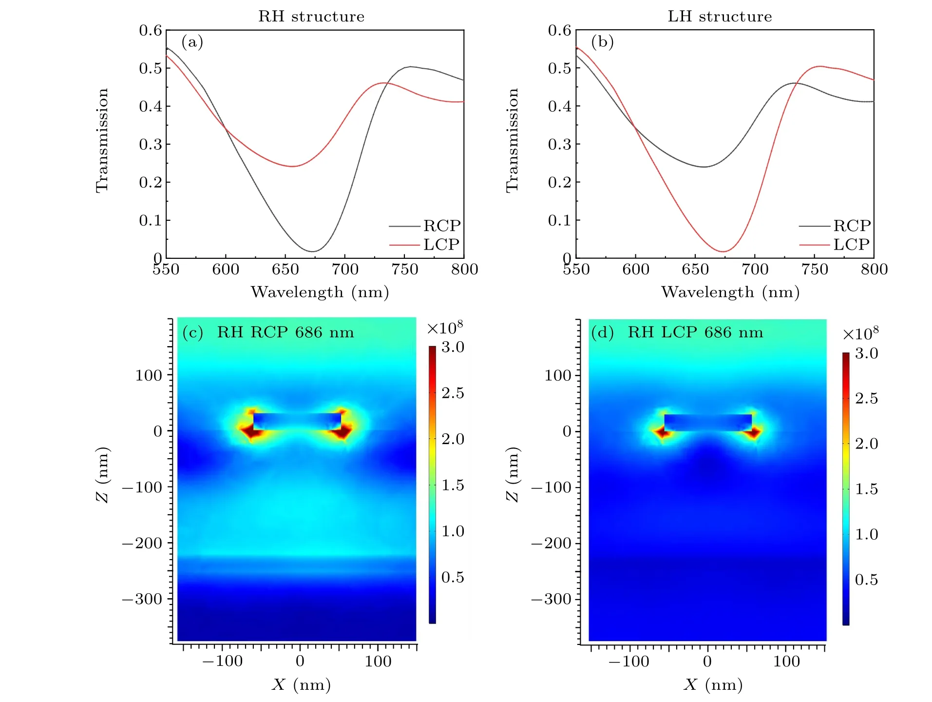
Fig. 2. (a)–(b) Simulated optical transmission spectra of (a) RH and (b) LH metamaterials without considering the waveguide modes, under the incidence of RCP(black line)and LCP(red line)light. (c)–(d)Intensity distributions of the electric field on the cross section at the wavelength of 686 nm(y cut),corresponding to the circular dichroism spectra dips under the(c)RCP and(d)LCP light of RH metamaterials,respectively.
3. Results
Let us first investigate the optical response of a conventional double layer Au grating. Here, the periodicities of the top and bottom gratings are both set to bePtop=Pbot=300 nm,and the thickness of the Al2O3layer is set to behwg=250 nm.In this case, the first-order TE and TM waveguide modes locate well below 500 nm (see Fig. S3), i.e., out of the range of (550 nm, 800 nm). The rotation angleθis chosen to beθ=45°for the RH structure andθ=135°for the LH structure, since the maximum CD could be achieved at these two rotation angles(see Fig.S4). Figure 2(a)shows the transmission spectra of the RH structure under LCP(red line)and RCP(black line) illumination. In either case, a transmission dip could be observed around 650 nm, which could be attributed to the excitation of the localized surface plasmon resonances(LSPRs)of the metal grating.It can also be seen from Fig.2(a)that the transmission for RCP is significantly smaller than that for LCP, which indicates that RCP illumination could excite the LSPR in the RH structure more efficiently. As shown in Fig.2(b), an opposite phenomenon could be found in the LH chiral structure,where the transmission for LCP is lower than that for RCP. To identify the transmission dips observed in Fig. 2(a), the spatial distributions of the electric field intensity are calculated for LCP and RCP illumination at the wavelength of 686 nm and are shown in Figs. 2(c) and 2(d), respectively. In both cases, the electric fields are found to be localized around the corners of the metal gratings,which correspond to the excitations of the LSPRs.

Fig. 3. (a)–(b) Simulated optical transmission spectra of (a) RH and (b) LH metamaterials with considering the waveguide modes, under the incidence of RCP(black line)and LCP(red line)light. (c)–(d)Intensity distributions of the electric field on the cross section at the wavelengths of 635 nm(y cut),corresponding to the circular dichroism dips under the(c)RCP and(d)LCP light of RH metamaterials,respectively. (e)–(f)Intensity distributions of the electric field on the cross section at the wavelengths of 660 nm(y cut),corresponding to the other CD spectra dips under the(e)RCP and(f)LCP light of RH metamaterials,respectively.
To investigate the waveguide mode coupling effect, the periodicity of the top Au grating needs to be increased to red-shift the first-order waveguide modes to overlap with the LSPRs. As seen in Fig. S3, when the periodicity of the toplayer grating is set toPtop=425 nm,the first-order waveguide modes forhwg=250 nm could be excited around 650 nm.Figures 3(a)and 3(b)show the calculated transmission spectra of RH and LH structures with a periodicity ofPtop=425 nm under RCP and LCP illuminations,respectively. Due to the coupling between the waveguide modes and the LSPRs, in each case three main transmission dips exist within a wavelength range from 600 nm to 720 nm. The transmission for RCP is lower than that for LCP in the RH structure,and vice versa in the LH structure. It is particularly interesting that the transmission features under RCP illumination exhibit a spectral position shift with respect to that under LCP illumination. In this case,the transmission peak may overlap with the transmission dip for the circular polarization with opposite handedness. For example, as shown in Fig.3(a), a transmission peak could be observed at 635 nm for LCP in the RH structure,while a transmission dip appears at the same wavelength for RCP,which is thus expected to generate a large CD.Similar situations could be found for the LH structure,as shown in Fig.3(b).
Figures 3(c)and 3(d)show the field intensity distributions of the transmission peak for LCP and the transmission dip for RCP at 635 nm in the RH structure. In the RCP case, the features of both the first-order TM waveguide mode and the LSPRs could be clearly seen,which indicates strong coupling between the waveguide mode and the LSPRs (Fig.3(c)), and thus resulted in the formation of a transmission dip. However,as shown in Fig.3(d),the intensity of the waveguide mode in the LCP case is much weaker than that in the RCP case,which indicates that, under LCP illumination, the coupling between the waveguide mode and the LSPRs at 635 nm is quite weak.Due to the large difference in coupling strength between the LCP and RCP cases at the same wavelength,the transmission dip for RCP overlaps with the transmission peak for LCP.The field intensity distributions are also calculated for RCP and LCP illuminations at 660 nm in the RH structure. It can be seen in Figs. 3(e) and 3(f) that the features of the first-order TE waveguide mode and the LSPRs under RCP illumination are much stronger than that under LCP illumination,which indicates that strong coupling between the TE waveguide mode and the LSPRs occurs at 660 nm for RCP,and weak coupling occurs at 660 nm for LCP.As a result,the transmission dip observed at 660 nm for RCP again overlaps with the transmission peak for LCP.

Fig.4. (a)–(b)Simulated circular dichroism spectra for both the RH structure(a)and the LH structure(b)without considering the waveguide modes(black line)and considering the waveguide modes(red line). (c)CD signal in the RH structures with different periodicities of the top gratings. (d)Change of CD signal of RH structure under different the period of the top grating in the wavelength of 600 nm–650 nm.
After obtaining the transmission spectra under LCP and RCP illumination, the CD values are calculated using CD=TR-TL. Figure 4(a) plots the CD value obtained from the hybrid RH structure (hwg=250 nm andPtop=425 nm, i.e.,with the waveguide-mode coupling effect)as a function of the wavelength. For direct comparison, the CD values for a conventional RH structure(hwg=250 nm andPtop=300 nm,i.e.,without the waveguide-mode coupling effect) are also shown in Fig. 4(a). It can be directly observed that the CD could reach a value as high as 0.52 at 635 nm and 0.43 at 660 nm in the hybrid structure. Compared with the CD value of~0.12 obtained in a conventional RH structure, the maximum CD value in the hybrid RH structure could be enhanced more than 4 times. As shown in Fig. 4(b), the same CD enhancement could be achieved in the hybrid LH structure at 635 nm and 660 nm, which provides evidence that the coupling between the waveguide modes and the LSPRs could significantly enhance the CD.
Figure 4(c) shows the calculated CD spectra in the RH structures with different periodicities of the gratings. Several bright branches with obvious anti-crossing behavior can be clearly seen, which verifies the occurrence of the strong coupling between the TE and TM waveguide modes and the LSPRs. The CD values initially increase with the increase in the periodicity of the top grating, and reach the maximum value aroundPtop=425 nm due to the coupling between the waveguide modes and the LSPRs. Further increasing the periodicity of the top grating moves the waveguide modes away from the LSPRs,i.e.,weakens the coupling between the waveguide modes and the LSPRs,and thus leads to a decrease in the CD value.
To more clearly demonstrate the spectral tunability of the enhanced CD bands, the CD spectra in the hybrid RH structures with typical periodicities ofPtop= 410 nm, 415 nm,420 nm, 425 nm, and 430 nm are plotted in Fig. 4(d). It is clearly seen that with the increase in the periodicity from 410 nm to 430 nm, the CD band continuously shifts from 624 nm to 638 nm, while keeping its maximum value higher than 0.45. This is because the change in the grating period could lead to a change in the spectral positions of the waveguide modes,[25]and eventually causes the shift of the CD band.In addition to the periodicity of the top grating,the other geometrical parameters,such as the thickness of the Al2O3layer(hwg) and the periodicity of the bottom grating (Pbot), could also be employed to tune the spectral position of the CD band.For example,as shown in Fig.S5,the CD band of the hybrid structure with fixedPtop=440 nm andPbot=300 nm could be tuned from 650 nm to 700 nm by increasinghwgfrom 260 nm to 310 nm,and the CD band of the hybrid structure with fixedPtop=440 nm andhwg=260 nm could be tuned within the wavelength range from 720 nm to 740 nm by increasingPbotfrom 420 nm to 480 nm.
4. Conclusion
In summary, we have demonstrated that, with the aid of the coupling between the waveguide modes and the LSPRs,the CD in the transmission spectra of a hybrid chiral structure consisting of double-layer Au gratings separated by a dielectric waveguide layer could be significantly enhanced. Compared with the CD value of the conventional double-layer grating without the waveguide coupling effect,the maximum CD in the hybrid structure could be enhanced more than 4 times.We also demonstrated that by varying the geometrical parameters, such as the periodicity of the grating and the thickness of the waveguide layer,the enhanced CD band could be tuned in a wide spectral range. We hope the proposed hybrid double grating and waveguide structures could have potential applications in chiral selective imaging, sensing and spectroscopy,especially where transmission measurement is required.
Acknowledgment
Project supported by the National Natural Science Foundation of China(Grant No.11474215).
- Chinese Physics B的其它文章
- A design of resonant cavity with an improved coupling-adjusting mechanism for the W-band EPR spectrometer
- Photoreflectance system based on vacuum ultraviolet laser at 177.3 nm
- Topological photonic states in gyromagnetic photonic crystals:Physics,properties,and applications
- Structure of continuous matrix product operator for transverse field Ising model: An analytic and numerical study
- Riemann–Hilbert approach and N double-pole solutions for a nonlinear Schr¨odinger-type equation
- Diffusion dynamics in branched spherical structure