
Electromagnetic and Thermal Characteristics of Molybdenite Concentrate in Microwave Field
2023-12-28 09:11JIANGYonglin蒋永林WUQuan
JIANG Yonglin(蒋永林), WU Quan(伍 权)?剼?
School of Metallurgical and Electrical Engineering, Guizhou Normal University, Guiyang 550025, China
Abstract:In modern metallurgical industry, microwave thermal technique has many advantages as one efficient energy treatment in an electromagnetic form, such as internal self-generated heat, easy access to control a volumetric heating process, and consensus on cleanliness, convenience and high efficiency of energy use. Both permittivity and permeability of molybdenite concentrate were measured for a further discussion about its electromagnetic heating coupling. A bidirectional coupling physics field in numerical modeling was undertaken to evaluate the microwave absorption potential and dielectric heating performance of molybdenite concentrate by the multi-physics finite element method. The electromagnetic morphology and the field distribution strength were described in the microwave reaction cavity. The electromagnetic field strength and the dissipation coefficient induced by temperature variation were represented throughout the whole heat chamber and at key parts of interest. Dependent temperature distribution was compared with that being obtained from a scenario by thermal conduction with a stable heat source. The molybdenite concentrate would be heated at surrounding temperature up to 593 ℃ for 10 min by microwave energy that was transmitted by a rectangular waveguide. Scanning electron microscopy (SEM) patterns suggested that the polished and neat crystalline molybdenum trioxide(MoO3) products were achieved by the microwave heating process. The superiority via utilizing microwave thermal technique is expounded in the preparation strategy for molybdenum oxide or molybdenum metal.
Key words:microwave energy; temperature characterization; thermal analysis; molybdenum trioxide(MoO3)
0 Introduction
Microwave is an electromagnetic wave within the frequency range of 3×10⁸to 3×10¹¹Hz[1]and has various applications in the field of material heat processing or pyrometallurgical technologies. With a radiation of microwave into a sample, the heat can be generated from the transformation of electromagnetic energy due to polarization effects of inner dipoles[2]in the sample that then will be heated up to a high temperature. As well-known, heat generated by microwave is beneficial for a specimen which is natively characterized from a good dielectric property and homogeneity because of microwave’s superior thermal generating properties such as heating selectivity, temperature uniformity, a fast heating rate, easy control and high efficiency in saving energy[3]. Many products prepared from microwave thermal technique will get a more regular microstructure, and thus their microstructural and mechanical characteristics can be enhanced. The frequency of 915 or 2 450 MHz is independently utilized in the present microwave heating equipment in order to eliminate interference from abundant frequencies by other wave generators like radar and communications and to standardize microwave apparatuses and practice conditions. The waveguide device, which can guide the directional transmission of electromagnetic waves, is generally classified into three sorts as rectangular, circular and coaxial lines[4-5], with kinds of matching model components and frequency ranges, conforming to the requirements by different technical specifications.
Molybdenite concentrate is the primary mineral source for diverse molybdenum productions. The preparation of molybdenum trioxide(MoO3) is a fundamental project in modern molybdenum industry. The melting point of MoO3is 795 ℃[6]. Microwave energy is eco-friendly and economic[7], alternative in pyrometallurgical decomposition of molybdenite concentrate. The introduction of microwave thermal technoique into the preparation of molybdenum products will be prospective. Therefore a clear understanding of the systematical controlling mechanism is necessary. A previous work involved the good dielectric properties of the molybdenite material, and the potential absorption capacity to electromagnetic energy[8]. Yet, for the elimination of time-consuming, high-cost and trial-and-error experiments, and for enhanced predictability and theoretical support on the veritable microwave heating process, a valuable mathematical model combining intrinsic equations with finite element interpolation calculation is developed with a prospective electromagnetic field and associated evolution mechanism. It would make the whole processes more tunable, predictable, efficient and feasible, and naturally lead to the reduction in manufacturing and energy consumption. Studies on microwave thermal analysis and effects of internal reaction mechanism upon various production applications have been done[9-11]. However, the representation of expected benefits by usefulness and accuracy from the perspective of theoretical assessment somewhat remains absent. Apparently, a novel experimental phenomenon may need to be expounded, drilled down and unified ulteriorly with the insights of theoretical explanations. Experimental implementation would receive inventiveness or new definability from theoretical support of models.
By means of an electromagnetic-thermal physics coupling approach[12], the electromagnetic shape within the concentrate sample and the Joule heat density distribution under the microwave condition is presented in this investigation. The temperature distribution within the samples generated by a conventional heating process and a microwave one respectively has been compared. Referring to relevant measurement results, the excellent performance of microwave heating is evaluated. The developed three-dimensional model with a better approximation of actual conditions can enhance the reliability of prediction on real physical environment. Pilot experimental result is involved to validate the modelling method. This numerical calculation is assessed to be concise and effective, with certain significance in theoretical guidance for material design and preparation of target products. The present model is also valuable in eliminating time-consuming, expensive and trial-and-error experiments. This numerical model would also make a clearer and profounder understanding for novel experimental phenomena and potential mechanism, and rationally construct a required circular feedback between theory and practicality.
1 Theoretical Expression
1.1 Electromagnetic equations

(1)
whereε=ε′-jε″,μ=μ′-jμ″, and they are respectively the complex permittivity and the complex permeability, with the real parts being devoted respectively asε′=εrε0andμ′=μrμ0, byε0andμ0respectively representing the permittivity and the permeability in free space, andεrandμrrepresenting the relative permittivity and the relative permeability, respectively. It should be noted that the magnetic conductivity is absent because the flow of magnetic charges is from a fictitious source only for a mathematical convenience, and the actual magnetic current source is followed by the loop of the electric current or some analogous types of magnetic dipole.
The power absorbed volumetrically by the dielectric molybdenite concentrate in microwave radiation is
(2)
which principally pertains to one equivalent results from Joule’s law. Even for non-magnetic materials, the second term on the right side of Eq. (2) is always present. Internal heat[14]is generated along the high frequency excitation of particulates under microwave radiation at a certain transmission range within the lossy material and transferred throughout the interrelated molecules. Consequently, the temperature of the material rises, and its microstate in thermodynamics would be constantly updated. Thus with a bidirectional coupling of the electromagnetic field and the thermal field, the energy conversion between medium polarizability and heat generation can be portrayed through resolving iteratively the heat transfer govern equation[15]for the temperature variation that is a function of time and space:
(3)

Many researches in microwave application involve a perfect electric conductor boundary which generally exists in a modal or harmonic analysis of high-frequency electromagnetic field simulation. With a finite conductivity by the perfect conductor whose electric field in the tangential component is considered to be “shorted out”, the skin depth is limited to be infinitesimal as the conductivity goes to infinite. The boundary is an electric wall and the related analysis concept can be cast asn×Et=0, wherenis the normal unit vector pointing out of the surface of a perfect conductor, andEtdevotes the electric field component in the continuous interface tangential direction.
It is similar to the explanation above for relative permeability, where magnetic current is hypothesized to be a fictitious source from mathematical considerations instead of physical constitutive. The magnetic wall boundary condition is not actually existed in practice and may be estimated by a corrugated surface, but it ensures a degree of completeness in general expressions at arbitrary interface and could be a reasonable assessment. To avoid leaks and losses of microwave from the heating oven, copper and aluminum were adopted to be the shielding surface[16]that were coated inside the walls of the waveguide and the furnace chamber, respectively.
1.2 Modelling and boundary conditions
In the present work, a three-dimensional model was considered into the better construction on actual working conditions instead of a symmetrically simplified two-dimensional model which might give rise to deficiency for real self-heating processes[17]and be less reliable in predicting production procedures. The establishment of the finite element model and the iterative process of solving the governing equations, coupling with different physics fields, were implemented by the Comsol Multiphysics program package in the present numerical investigation. A cylindrical cavity crucible with silicon carbide composition is utilized to load the molybdenite concentrate and is considered as the media domain rather than the boundary state in the simulation. The waveguide and the furnace cavity are established with the outside boundary of the air domain being copper and aluminum substrates, respectively. A rectangular waveguide equipped with the magnetron in a TE11dominate model was exploited as a microwave source. Figure 1 shows the geometry model as the schematic configuration, with relative dimensions shown in Table 1, in whichL,W,HandRpresent the length, width, height and radius to the corresponding component, respectively, and subscripts c, rw, cw, cr and hw denote the components of the cavity, rectangular waveguide, circular waveguide, crucible and heating wire. The circular waveguide with good effectiveness is believed to be appealing to audience, while relevant report about the selection of the circular type remains unavailable to a large extend. The efficiency of the circular waveguide on microwave heating was studied with comparison to that of the rectangular waveguide. For two types of waveguides, the cross-sectional area is the same in order to ensure the same power density.

Fig.1 Microwave heating chamber for an assessment on predefined finite element: (a) geometric model; (b) mesh model (unit: m)
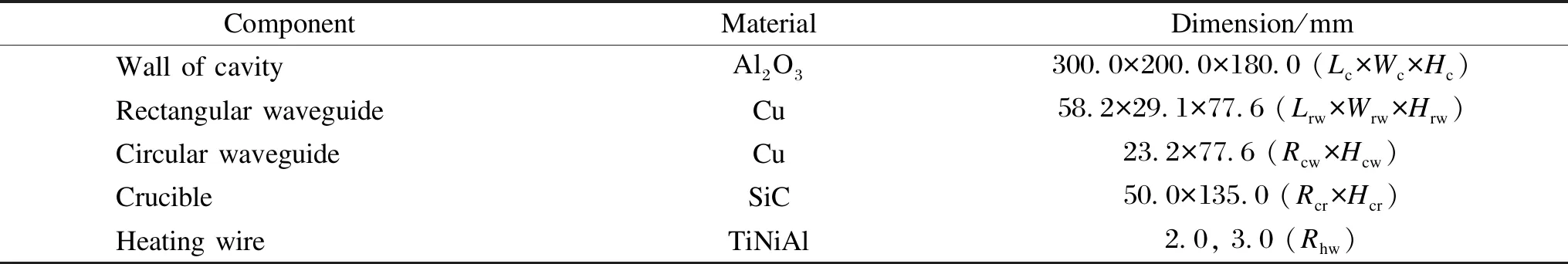
Table 1 Dimensions of model geometry and corresponding materials
In addition to the rationality of the geometric model itself, the meshing is also a key factor in the establishment of the finite element model, with the purpose of maximizing forwardly the accuracy of the numerical analysis. The geometric part with prismatic conformation was subdivided into a tetrahedron element. While for those parts with curved surfaces, it is necessary to consider the division by mapping or sweeping fineness, with the maximum element size of the air domain being 1/10 of the wavelength of the electromagnetic wave in the lossless medium. The overall grid has sufficient uniformity and continuity to prevent the difficulty of convergence of the iterative process and casual use of the calculation results without good precision.
The microwave heating is demonstrated as the solution sequence alternating between an electromagnetic harmonic analysis and a transient heat transfer analysis. The former calculates Joule heat generation result, and the latter is used to predict a time-dependent temperature solution. The temperature distribution obtained from each solution step changes the dielectric strength distribution within the dielectric material and vice versa. Therefore, this analysis requires an iteration between two kinds of calculation procedures until the desired level of convergence is achieved. The entire electromagnetic-thermal coupling process is thus a numerical process of solving the Maxwell’s equation and the heat transfer equation alternately.
The microwave field generated by a continuous wave magnetron is transmitted through the waveguide into the heating chamber. Microwave would be absorbed and attenuated by the dielectric sample. The heat is generated from the transformed electromagnetic energy through the high-frequency motion combining vibration and rotation of polaron inside the material. This thermodynamic behavior of the target material could not be efficiently described by the finite element method. In the infancy stage, the interaction between microwave polaron and material particles at the contact surface is induced by a physical reaction, where the reflection of microwave is ignored. In the simulation processes, microwave also fails to be 100% converted. Then the thermal composition of the active components in the chemical reaction system, would quantitatively describe the thermodynamic behaviors for micro-components in the specified specimen, and the reaction efficiency and potential advantages are compared.
1.3 Experimental characteristics
The physicochemical properties of a molybdenite sample were generally defined through some physicochemical testing principles and computational techniques. The mineralogical analysis of the molybdenite concentrate was implemented by an X-ray fluorescence spectrometer (XRF, AXIOSmAX, Netherlands). The dielectric coefficients of the molybdenite concentrate were measured by a vector network analyzer (E5071C, Agilent, America) at a certain temperature range. Samples were heated up to the predetermined temperature in each measurement on dielectric properties. A water cooling device was assembled to maintain the reactor chamber and detector arrangement at appropriate low temperature. A tablet computer was connected from the inner control module to record the test results. The thermal conductivity and the heat capacity in a heat transfer analysis were determined by the LFA-457 HyperFlash (Netzsch, Germany)[18]. The apparent density was 1 250 kg/m3within a particle size of 50-200 mesh, and it was the initial value for the iterative computation[19].
2 Results and Discussion
2.1 Dielectric permittivity
Most of intrinsic properties induced upon temperature in a determined material involve a nonlinear solution in the transient thermal analysis. The dielectric property of molybdenite concentrate in Fig.2 is the principal factor, and it is the function of temperature and activation energy. The dielectric characterizations at high profile show that the molybdenite concentrate has a strong interaction with microwave. Key coefficients suggest the potential thermodynamic behaviors of the molybdenite concentrate under microwave treatment, and all of them are defined in an initial boundary condition and would cause substantial influence on the relevant results in a numerical assessment. Overally, the eigen characteristics which are associated in the specified specimen are of importance for target schemes.

Fig.2 Essential attributes of molybdenite concentrate along with temperature variation: (a) dielectric constant; (b) dielectric loss factor; (c) thermal conductivity; (d) specific heat
2.2 Permeability
The results shown in Fig.3 demonstrate a flatly steady for the magnetic dielectric constant (i.e.permeability related to magnetization or magnetic polarization and susceptibility) at a low frequency range. The magnetic constant would be intensely excited under high-frequency excitation and it leaves a peak of 0.55 H/m at 2.66 GHz. Although the permeability parameter is approximately lower by an order of magnitude than that of permittivity (Fig.2(a)), the molybdenite concentrate would be induced a higher polarization intensity in magnetic response near the universal microwave frequency of 2.45 GHz. The magnetic susceptibility at 2.45 GHz is caused by spin magnetic dipole moments, and the relative polarization dynamics[20]would be contributed to energy transformation between the electromagnetic field and the thermal field.
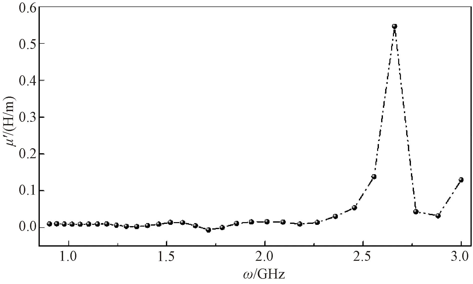
Fig.3 Permeability constant versus frequency ω of molybdenite concentrate
The constituents from molybdenite concentrate have been determined by the chemical elemental analysis method as indicated in Table 2. The mass fractions of Mo and S are about 44.64% and 28.17%, respectively. This may be attributed to the fact that dominant component of molybdenite concentrate is MoS2. Many impurities like SiO2, Cu, CaO, and Pb are determined in the composition detection. It could be assumed that the proper treatment process of wet leaching could lead to a further purification of this molybdenite concentrate. Notably, the magnetic elements (generally regarded as Fe, Co and Ni) are absent.

Table 2 Main elemental components from molybdenite concentrate
Contrasting to measurement results in Fig.3, the permeability susceptibility of the specimen is not involved in the intrinsic magnetism of its internal atoms, but in the inherent formation of intermolecular magnetic dipoles in the component system of the specimen considered. This result might has been overlooked in Refs.[13, 19].
2.3 Electromagnetic characterization
Once the microwave is fed into the heating cavity, penetration and reflection are sustained around the crucible that loads the sample of molybdenite concentrate, and the high-frequency vibration and rotation among the material molecules would be induced to the generation[21]of heat energy under microwave radiation. The electromagnetic field distribution and power flow strength are firstly of interest. Figure 4 shows the electric field vector, the magnetic field vector and the power flow by microwave treatment imposed through the rectangular waveguide and the circular waveguide. The electric field, the magnetic field and the power flow direction are tended to be perpendicular to each other at one cross-section and simultaneously perpendicular to the transmission direction of microwave, thus forming a space right angle coordinate orientation. Because the power flow direction in the electromagnetic field represents the transmission direction of microwave itself, the orthogonal vector relationship among the electric field component, the magnetic field component, and the direction in energy travel (Poynting vector) is constantly presented in the microwave field. From the illustration of these vector relationships, the real propagation form in the microwave is represented. The vibrating directions of the cosine wave from the electric field or magnetic field are perpendicular to each other and again to the propagating direction (also to the direction in energy flow) in a microwave field. It should be noted that the average power flow delivered by the rectangular waveguide is higher than that by the circular waveguide, and the energy transfer efficiency from the former would be more significant. In addition, the dielectric strength is higher than the magnetic strength of the molybdenite concentrate, the absorption of the electric field mode by the molybdenite concentrate from the microwave propagated through a rectangular waveguide is stronger than that through a circular waveguide, and then a higher power density is distributed in the central region of the absorbing material. It can be presumed that a higher temperature would be achieved when the material is heated by the microwave which is propagated by a rectangular waveguide other than that by a circular waveguide. Besides, the entire heating chamber is full of the electromagnetic field, which is mainly attributed to the occurrence of scattering and reflecting loss when the microwave is fed into the heating chamber.
Field vectors in Fig.4 reveal the orientation, the morphology and the flux density for the electromagnetic fields in the maximum probability, but somewhat fail to show the distribution of field components at the media surface. A surface map is displayed for the electromagnetic field intensity distribution as shown in Fig.5. It should be noted the electric field intensity is numerically higher than the magnetic field intensity by three orders of magnitude. The result might expound the interaction between material particles and the electric field is higher than that between the particles and the magnetic field. Then the absorption intensity of the electric field by the material is higher than that of the magnetic field. According to characterization results mentioned, the magnetic properties of the molybdenite concentrate is insignificant compared with the dielectric performance. Because of the absence of magnetic atoms, the existence of slight magnetism may be due to the formation of little magnetic moments caused by the arrangement of internal atoms. Hence the contribution on loss mechanism and the efficiency of energy conversion from the microwave into a thermal source or heat eventually rise from the dielectric loss. For non-metallic magnetic substance, for example ferrites, the absorption to the microwave is determined by both the permittivity and the permeability. But for a non-magnetic material, the magnetic effect would be neglected. This could be a reason that so many reports mainly focus on the interaction of electric fields in the microwave but little on that of magnetic fields. Further, the transverse electric fields of a rectangular waveguide validate that the transverse electric field components are dominated in the propagation of the microwave along into a furnace chamber, and the electromagnetic distribution in a specified furnace cavity is related to the selection of the waveguide modes. In the following discussion about the microwave penetration depth in a lossy material, the skin depth will be equivalently expressed as a function of the dielectric constant. The electric field components are more often considered in the application of microwave technology.
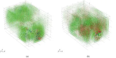
Fig.4 Schematics of electric field vector (red arrow), magnetic field vector (green arrow) and power flow (blue arrow) within microwave treatment chamber in a front view by a production on the transmission: (a) rectangular waveguide; (b) circular waveguide (vector modes schematically indicate orientation and distribution density without color bar existed in a contour map)

Fig.5 Field intensity distribution in heating oven by microwave feeder through rectangular waveguide: (a) electric field; (b) magnetic field
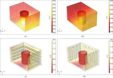
Fig.6 Temperature generation in molybdenite concentrate that was loaded inside a cylindrical alumina crucible from heat generation by microwave radiation and thermal conduction: (a) rectangular waveguide; (b) circular waveguide; (c) helical-coil wire; (d) U-type wire
2.4 Thermal characterization
The energy conversion efficiency from electromagnetic energy to heat through different microwave transmission modes can be estimated by temperature rising under the same radiation time and microwave power. Figure 6 shows the temperature range formed by the same heating process under the microwave treatment. A higher temperature of 750 ℃ achieved via the rectangular waveguide is compared to 650 ℃ achieved via the circular waveguide. The result is obtained from a transient process with a time step in 10 s up to 10 min, and the port input power of 10 kW in the microwave is defined similarly to both the rectangular waveguide and the circular waveguide. The fact that the temperature from the circular waveguide is lower than that from the rectangular waveguide may be due to a lower power density induced upon an incongruity between the size of the cross-section and that of the transverse field components at corresponding transverse modes. This result indicates that the rectangular waveguide might be more widely favourable in a practical application.
To gain a clearer vision of what goes on at the temperature dependence by different heat generation methods, a similar temperature result is displayed between the microwave and conventional heat sources which are held by a hot-wire with two types of configurations, namely a U-form tube and a helical-coil tube. The heat treatment process is natively influenced by the thermodynamic mechanism of a heat transfer in solids. As shown in Figs. 6 (c) and 6 (d), the temperature of molybdenite concentrate from the hot-wire heating is lower than that from the microwave heating. The temperature obtained by the helical-coil wire heating is higher than that by the U-type wire heating. This is due to the fact that a larger surface area held by the former can conduct more heat than that by the latter under the same heat source. Therefore, for a higher heat transfer efficiency, the helical spring in a resistance furnace would be more considered in practical application. In addition, it is obviously seen that the temperature rising to high value by the microwave is generated at the beginning and inside of the material, and it is inevitably in a tendency of diffusion to the outside. This is roughly the opposite to the way how thermal heat diffuses in conventional heating pathways. The advantage of the microwave heating by self-generated heat from the molybdenite concentrate with high temperature-rising efficiency and heat energy utilization, is substantially demonstrated in this study. The microwave energy is sufficiently converted to heat in the raw material under a certain microwave penetration.
The average temperature simultaneously indicates the temperature uniformity and the heating rate. The result for the molybdenite concentrate is shown in Fig.7. It might be expected that the heating efficiency for the molybdenite concentrate decreases sequentially in the scenario for the rectangular waveguide, the circular waveguide, the helical-coil wire, and the U-type wire at the established model scale. This result may provide a theoretical guidance for optimal selection of waveguides and furnace wires in the pyrolysis process by an upgraded industrial-grade high-temperature furnace.

Fig.7 Average temperature of molybdenite concentrate by different methods: (a) rectangular waveguide; (b) circular waveguide; (c) helical-coil wire; (d) U-type wire
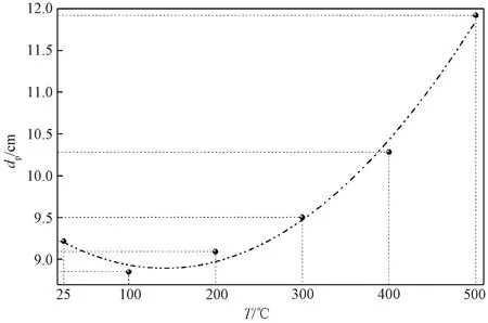
Fig.8 Penetration depth variation along with temperature in molybdenite concentrate
2.5 Microwave penetration depth
Along with the propagation of the microwave into a material, the conversion of electromagnetic energy into heat occurs and consequently makes an attenuation in electromagnetic energy because of the interaction between the microwave and the microparticles in the material. The electromagnetic energy of the microwave is reduced by 37%[22]of its initial value at the surface of material. The distance along with the dissipation of energy is defined as the penetration depthdpof the microwave into the material and is mathematically derived:
(4)
whereωis the frequency of the electromagnetic wave, andω=2.45×10⁹s-1;ε0andμ0are respectively the permittivity and the permeability in free space,ε0=8.854×10¹²F/m andμ0=4π×10-7H/m;ε′ is the real relative permittivity or dielectric constant, and universally represents the absorbing and storing capacity for the microwave by a specified material; the imaginary part of complex permittivityε″ is the dielectric loss coefficient and stands for a proportion of attenuation and degradation by the microwave among molecular interstitials along the travel route of the electromagnetic wave within a considerable media; tanδ=ε″/ε′, and is the loss tangent at a certain frequency and identified as the transformation efficiency from microwave energy into heat within the specified dielectric material. It is worth noting that the penetration depth is very low in a good conductor like the most metals. For example, the penetration depth of copper is 6.6×10⁻⁷m. Thus good conductors are usually used to shield microwaves.
The characteristic penetration depth of the regular material (lossy media) lies in the sample dimension and thus meets the microwave heating conditions for those materials. Figure 8 shows variation of the microwave penetration depth of molybdenite concentration with temperature rising from 25 ℃ to 500 ℃ measurably. At an initial stage, the penetration depth slightly decreases because of the domination of microwave absorption at the full reaction period between the microwave and microparticles. As the temperature rises, the thermal movement of the internal molecules intensifies, the molecular spacing increases and the overall structure expands to a certain extend. Hence the penetration of the microwave is enhanced. It can be inferred that the penetration is related to an apparent density of the specified material, and a systematic detection would be expected. Consequently, the penetration depth gives a rational assessment on uniformity and attenuation intensity in the interaction range.
2.6 Microscopic patterns
According to the discussion above, under the excitation of microwave radiation, the efficiency of heat and mass transfer can be promoted, the internal molecules tend to be arranged regularly, and then the adjusted nucleation and crystallization might be more strongly induced. By an oxidation roasting and sublimation-condensation routine of molybdenum concentrate, MoO3can be prepared. A preliminary survey has been conducted, and a systematic research would be worth looking forward. As shown in Fig.9, MoO3obtained under the microwave process holds obviously higher crystallinity, regularity and homogeneity than that obtained under the conventional conduction heating, for which the MoO3structure is loose. Then the refinement of MoO3from the molybdenite concentrate by microwave energy could be predictable with an efficient and continuous pyrolysis process, and the final product exhibits superior microscopic morphology[23]. In view of an improved microstructure and enhanced mechanical strength of the final product, the advantages of the microwave heating processing for many dielectric minerals have been divulged to a desired preparation process.

Fig.9 Micrography pattern of MoO3 products: (a) microwave heating; (b) conduction heating
An earlier effort inspected the dielectric properties and the penetration depth varying with the temperature and the apparent density, and the good adsorption properties of the microwave for the molybdenite concentrate were suggested[24]. Here, MoO3obtained by microwave heating has higher purity and crystallinity compared to that obtained by electric furnace heating. This numerical result significantly supports the feasibility and the efficiency of microwave thermal technique in pyrolysis or heat sublimation. A systematical clarification concerning with microscopic mechanisms of active components in this type of mineral materials would be expected in a further research.
3 Conclusions
In this paper, the microwave field construction was described by a three-dimensional finite element model through a microwave treatment cavity with certain domain parameters. The measurement on permittivity and permeability indicated that molybdenite concentrate possessed good dielectric properties and microwave adsorption potential. The electromagnetic field model in the propagation of the microwave was presented, and it was found that the effect of the electric field component on the generation of heat energy was better than that of the magnetic field component in the TE11mode of the rectangular waveguide within the molybdenite concentrate. The thermal progress of the molybdenite concentrate was developed and discussed through microwave excitation and through a heat field by convection and radiation from the heat source respectively by a helical-coil wire and a U-type wire. The heating rates for the condition at rectangular waveguide, circular waveguide, helical-coil wire and U-type wire were 0.989, 0.808, 0.740 and 0.717 ℃/s in 10 min, respectively. Thermal decomposition for molybdenite concentrate by the microwave would be appraisal, and the rectangular waveguide might be selective in an experimental synthesis or in a molybdenum industry. Microwave penetration depth within the molybdenite concentrate was evaluated to be reasonably well, and thus the good heating uniformity was obtained. The micrographs demonstrated that MoO3with better crystallization property could be prepared from molybdenite concentrate through microwave thermal technology. The advantages from microwave metallurgy with clean and efficient process are prospective, and a systematical study on the production of MoO3by microwave energy might be done under certain process conditions.
 Journal of Donghua University(English Edition)2023年6期
- Journal of Donghua University(English Edition)的其它文章
- Laser-Induced Graphene Conductive Fabric Decorated with Copper Nanoparticles for Electromagnetic Interference Shielding Application
- Toughness Effect of Graphene Oxide-Nano Silica on Thermal-Mechanical Performance of Epoxy Resin
- Photoactive Naphthalene Diimide Functionalized Titanium-Oxo Clusters with High Photoelectrochemical Responses
- Preparation and Thermo-Responsive Properties of Poly(Oligo(Ethylene Glycol) Methacrylate) Copolymers with Hydroxy-Terminated Side Chain
- Synthesis, Characterization and Water Absorption Analysis of Highly Hygroscopic Bio-based Co-polyamides 56/66
- Design of Online Vision Detection System for Stator Winding Coil