
Effect of ion stress on properties of magnetized plasma sheath
2024-03-19 02:36LongCHEN陈龙ZuojunCUI崔作君WeifuGAO高维富PingDUAN段萍ZichenKAN阚子晨CongqiTAN檀聪琦andJunyuCHEN陈俊宇
Plasma Science and Technology 2024年2期
Long CHEN (陈龙),Zuojun CUI (崔作君),Weifu GAO (高维富),Ping DUAN (段萍),Zichen KAN (阚子晨),Congqi TAN (檀聪琦)and Junyu CHEN (陈俊宇)
School of Science,Dalian Maritime University,Dalian 116026,People’s Republic of China
Abstract In the plasma sheath,there is a significant gradient in ion velocity,resulting in strong stress on ions treated as a fluid.This aspect has often been neglected in previous sheath studies.This study is based on the Braginskii plasma transport theory and establishes a 1D3V sheath fluid model that takes into account the ion stress effect.Under the assumption that ions undergo both electric and diamagnetic drift in the presheath region,self-consistent boundary conditions,including the ion Bohm velocity,are derived based on the property of the Sagdeev pseudopotential.Furthermore,assuming that the electron velocity at the wall follows a truncated Maxwell distribution,the wall floating potential is calculated,leading to a more accurate sheath thickness estimation.The results show that ion stress significantly reduces the sheath thickness,enhances ion Bohm velocity,wall floating potential,and ion flux at the wall.It hinders the acceleration of ions within the sheath,leading to notable alterations in the particle density profiles within the sheath.Further research indicates that in ion stress,bulk viscous stress has the greatest impact on sheath properties.
Keywords: magnetized plasma sheath,ion stress,Bohm criterion
1.Introduction
In a plasma device,the different motion properties of ions and electrons cause the plasma in the region near the wall to deviate from electric neutrality.This region,with a scale ranging from a few to several Debye lengths,is referred to as the plasma sheath.The plasma sheath exhibits various unique properties,and studying it helps in understanding plasma transport processes,particle density profile,and the wall energy deposition at the boundaries of all kinds of plasma devices,such as experimental low-temperature discharging [1,2],tokamak scrape-off layer (SOL) and divertor [3,4],and industrial applications of plasmas [5,6].
In studies on the sheath,it is generally assumed that electrons are in a state of thermal equilibrium,with their density following a Boltzmann distribution,while ions are considered as a cold fluid,and their motion follows the fluid equations [7-9].When there is a velocity gradient in the fluid,adjacent fluid elements experience compression and friction against each other,which is known as viscosity.Friction acting parallel to the surface of the fluid element is called shear viscosity stress,while compression acting normal to the fluid element is called bulk viscosity stress.Additionally,the fluid element may also experience pressure normal to the surface.The composition of viscous stresses and pressure is known as fluid stress,which can be quantitatively described using a fluid stress tensor.The stress on the fluid element is shown in figure 1,whereprepresents fluid static pressure,Πij(i≠j) represents shear viscous stress,and Πi j(i=j)represents bulk viscous stress,i,j=x,y,z[10].
In 1845,Stokes extended Newton’s law of internal friction to arbitrary flow states of viscous fluids,deriving the generalized Newtonian stress formula:
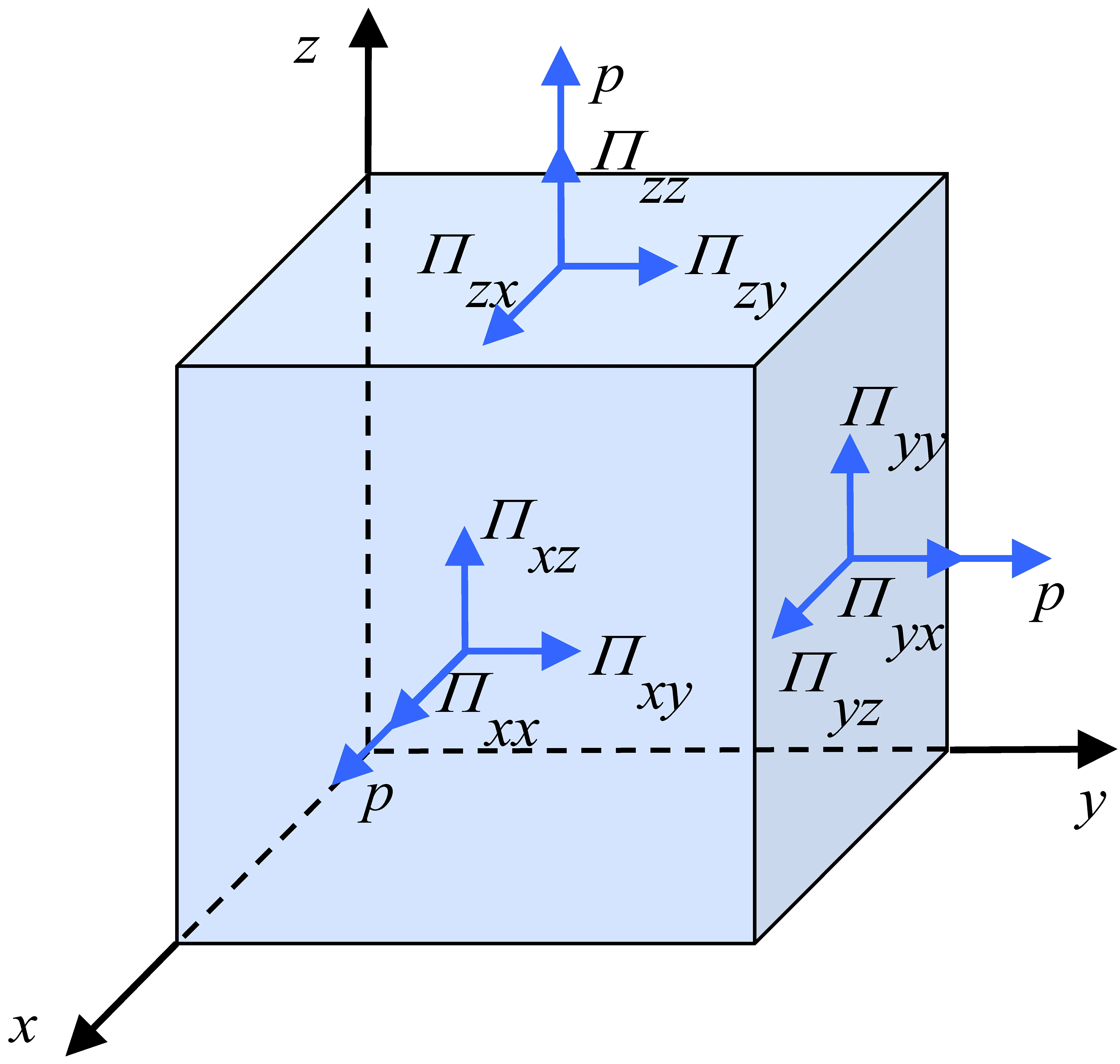
Figure 1.Stress on a fluid element.
wherePis the fluid stress tensor,Iis the unit tensor,and the
symmetric second-order tensor Π is the fluid viscous stress tensor:
where µ and µ′are the viscosity coefficients,vis the fluid velocity,S=[∇v+(∇v)T]/2 is the strain rate tensor,T represents transpose.Accordingly,the Navier-Stokes equation can be obtained:
which,together with the fluid continuity equation:
forms the partial differential equations describing the motion of the viscous fluid,where ρ is the fluid density,fis the external force on the fluid per unit volume [11-13].
In previous studies on the properties of the magnetized sheath,the stress tensor in the ion motion equations is often neglected,meaning that the influence of stress on ion motion is not considered [14-17].Some studies only consider the effects of thermal pressure and external fields [18-27].Generally,when ions enter the sheath,their velocity rapidly increases to several times the ion sound speed under the influence of the electric field.Due to the complex physical processes such as collisions and ionization that often accompany ions during acceleration [28],the ion density profile may exhibit fluctuations within a certain range [29].Constrained by the continuity equation,the ion velocity does not increase indefinitely,and its profile may also generate corresponding fluctuations locally.Because the scale of the sheath is only a few Debye lengths,resulting in significant velocity gradients of ions within the sheath.Therefore,the impact of viscous stress becomes non-negligible in this scenario.When supersonic fighter jets are flying at high speeds,the action of viscosity results in significant velocity gradients within the air layer adjacent their surfaces.Therefore,when conducting aerodynamic studies of aircraft in flight,it is imperative to consider the influence of viscous stress on the surrounding airflow [30,31].For even faster high-hypersonic vehicles such as satellites and intercontinental missiles,when they re-enter Earth’s near-space environment,their peak flight speeds can often reach several tens of Mach.The intense friction generates high temperatures,leading to ionization of the air around the vehicle’s surface,thus forming a plasma sheath and producing the phenomenon known as the “blackout” effect [32-35].Similar to the high-velocity airflow near the surface of fighter jets,there are significant gradients in ion velocity within the plasma sheath around high-hypersonic vehicles.Therefore,when analyzing the motion characteristics of ions,it is essential to account for the effects of viscous stress.
Wanget alhave conducted separate studies using a 1D3V fluid model to investigate the effects of ion shear and bulk viscous stresses on the properties of the steady-state magnetized sheath [36,37].The results indicated that these two stresses have a significant impact on the structure of the sheath.Moreover,the extent of their influence changes with variations in sheath parameters such as the magnetic field strength and ion-electron temperature ratio.In fact,both ion shear and bulk viscous stresses are related to the gradient of ion velocity and are not independent.Therefore,these two types of viscous stresses should be studied together as a unified entity.In previous studies,the electric drift velocity of ions at the sheath edge has commonly been used as the boundary condition for their transverse velocity [24,38-42].However,there exists a weak gradient in ion density within the presheath actually.Therefore,in addition to the electric drift motion,ions also undergo diamagnetic drift [43],this should be considered in the study of boundary conditions for ion velocities.
This work systematically investigates the impact of ion stress on the properties of magnetized plasma sheath using fluid simulation,with hydrogen plasma as the specific case.In section 2,a fluid model for magnetized sheath considering ion stress is established,where ion motion satisfies the steady-state fluid continuity equation and Navier-Stokes equation with the ion viscous stress tensor formulated by Braginskii [44].In section 3,considering the diamagnetic drift and electric drift motion of ions,the Bohm criterion and other boundary conditions that are well-fitted to the model are rigorously derived using the property of the Sagdeev pseudopotential.Additionally,by assuming a truncated Maxwell distribution for electron velocity at the wall,the wall floating potential is obtained,leading to a more accurate determination of the sheath thickness.In section 4,the definite problem of the sheath model is numerically solved,and the effects of ion stress and its different components on the sheath characteristics are compared and analyzed.Finally,a summary is provided in section 5.
2.Fluid model of sheath considering ion stress
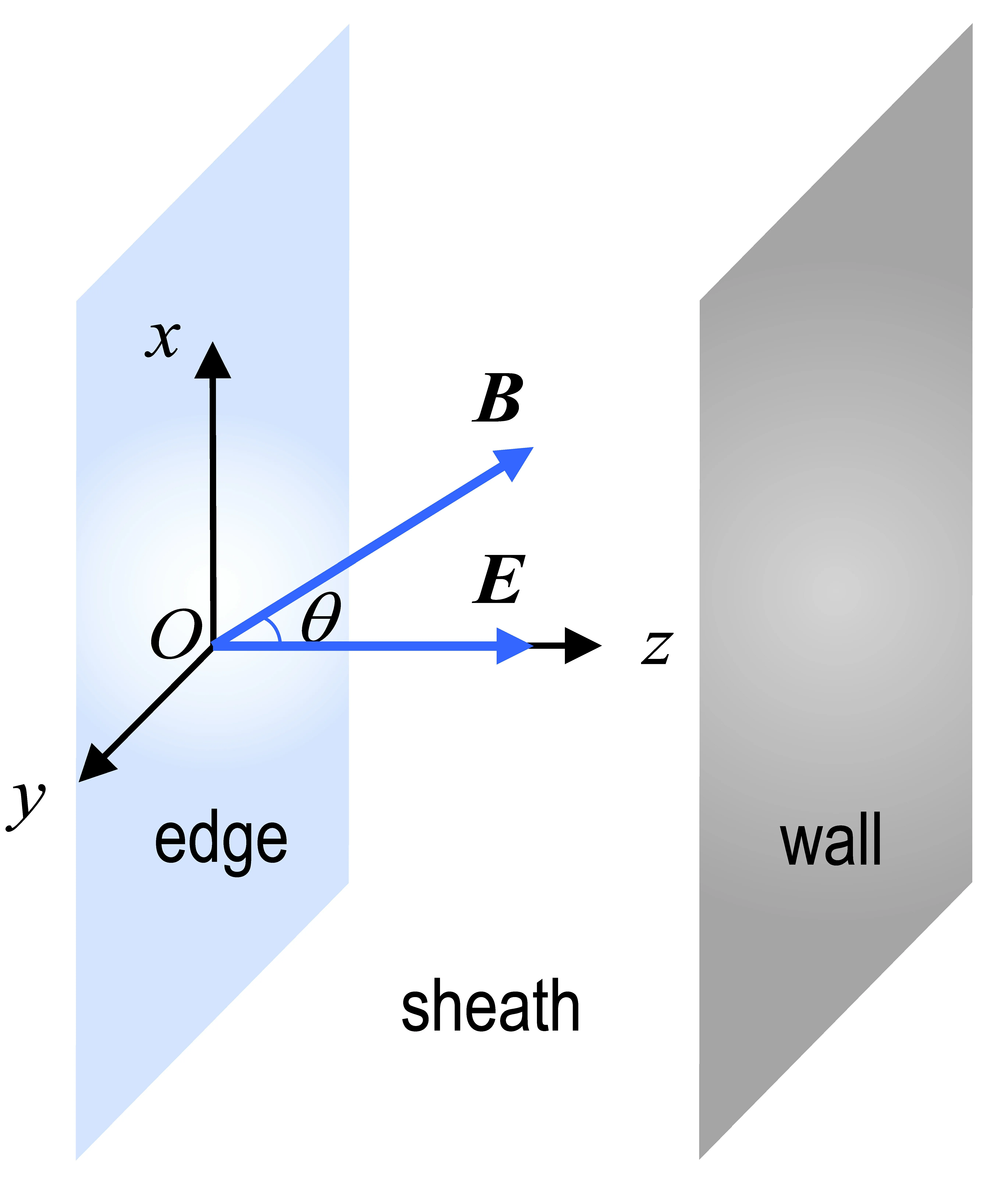
Figure 2.Geometry of the magnetized sheath model.
Firstly,the magnetized sheath model is established in the 1D3V domain shown in figure 2,where thez-axis is normal to the wall,and the coordinate origin is located at the sheath edge.There is an electric fieldEand a uniform magnetic fieldB=Bsinθex+Bcosθezpresent in the sheath,with θ representing the angle betweenBand they-zplane [45].
The scale of a plasma sheath typically ranges between a few and several Debye lengths,which is much smaller than the dimensions of most surfaces that contact with the plasma.Therefore,it can be approximated that the wall surface is an infinitely large plane.Physical quantities within the sheath possess translational invariance in the direction parallel to the wall,and they only vary in the direction normal to the wall surface,i.e.,∇=ezd/dz,andU=U(z),whereUis any vector field or scalar field in the sheath.
The electron density in the sheath follows a Boltzmann distribution:
wherene0is the electron density at the sheath edge,neandTeare the electron density and temperature in the sheath,eis the electron charge,and φ is the potential in the sheath.
The ion motion satisfies the steady-state continuity equation and Navier-Stokes equation:
wheremi,ni,vi,andpiare the mass,density,velocity,and thermal pressure of the ion in the sheath respectively.Πiis the ion viscous stress tensor,andfiis the external force on of statepi=niTi,equation (7) becomes:the ions per unit volume,which is assumed to be only the electromagnetic force in this work.Considering the equation
whereTiis the ion temperature.
The continuity equation (6) can be rewritten asniviz=const .Supposing thatni0andviz0are the ion density and velocity at the sheath edge,we have:
The potential and particle density in the sheath follow the Poisson equation:
where ε0is the vacuum permittivity.
A set of typical tokamak edge plasma parameters are taken to perform this study: the plasma densityn~1019m-3,the ion temperatureTi~5 eV,the electron temperatureTe~10 eV and the magnetic field strengthB~1 T.It can be estimated that the ion gyro frequency ωci=eB/mi≈9.6×107s-1,the ion plasma frequency4.2×109s-1,the electron-ion mean collision frequency νei≈6.9×10⁶s-1,and the ion-ion mean collision frequency νii≈9.1×10⁵s-1.The parameters satisfy ωci/νei,ii≫1,so for the ion viscous stress tensor Πi,we can use the expression provided by Braginskii in the presence of a strong magnetic field [44]:
where
and ηi(i= 0,1,2,3,4) are the ion viscosity coefficients:
From the previous discussion of the parameters,η0/η3= 1.92ωci/νii~2×102≫1 and η3/η1= 2η4/η2=5ωci/3νii~1.8×102≫1 ,so the terms containing η1and η3in equations (11) and (12),the term containing η1in equation (14),and the terms containing η2in equations (15) and(16) are negligible.It is worth noting that the aforementioned viscous stress tensor is in the form provided by Braginskii for a magnetic field parallel to thez-axis.Given that this work investigates a titled magnetic field,a coordinate transformation is necessary before applying Braginskii viscous stress tensor to account for ion motion under the tilted magnetic field.Consideringvi=vi(z),we have:
and
The main diagonal element of Πirepresents the ion bulk
viscous stress,and the off-diagonal element of Πirepresents the ion shear viscous stress.
To facilitate the analysis and the numerical calculation,we introduce the following dimensionless variables:ζ=z/λD,T=Ti/Te,Ω=ωci/ωpi,γ=νii/ωpi,Ne,i=ne,i/n0,Φ=eφ/Te,andu=vi/cs,wheren0is the plasma density at the sheath edge,is the electron Debye length,andis the ion sound speed.Substituting equation (22) into equation (8),and assuming that the plasma satisfies the quasi-neutrality condition at the sheath edge:
we then have:
where H1=T/Ω ,H2=0.96T/γ.According to equations (21)and (22),the force terms in equations (26) and (27) containing the coefficient H1are derived from the ion shear viscous stress,and the force term in equation (28) that contains H2is derived from the ion bulk viscous stress.H1and H2can be referred to as the shear and bulk viscosity coefficients,respectively,which can be used to describe the strength of these two viscous stresses.
3.Boundary conditions and modified Bohm criterion
Equations (24)-(29) constitute the ordinary differential equations (ODEs) describing the properties of magnetized hydrogen plasma sheath with six unknowns,which areNi,Ne,Φ,ux,uyanduz.It is necessary to give the boundary conditions for these unknowns to solve the ODEs above.The boundary conditions forNiandNehave been given in equation (23).Next,we derive the boundary conditions for the remaining variables by investigating the behavior of the plasma in presheath.
3.1.Ion velocities parallel to the wall
It is generally believed that there is a transition region between the sheath and the bulk plasma with a scale much larger than the sheath,in which ions enter the sheath at a certain velocity under the influence of a weak electric field,called the presheath.In fact,there is no strict boundary between the sheath and the presheath.Typically,the sheath edge is usually chosen as the location where the ion velocityuzreaches the ion Bohm velocityMi.In addition,it is considered that the electron density in the presheath follows a Boltzmann distribution and the quasi-neutrality condition still holds:
Then the Poisson equation in the presheath is:
The potential at the sheath edge Φ0is usually assumed to be 0,and the electric field strength is assumed to be a small amountE0:
Assuming that the electromagnetic field in the presheath is uniform and steady,under the influence of the electric field and the gradient of ion density,ions in the presheath will undergo electric drift and diamagnetic drift motion.The electric drift velocity is:
and the diamagnetic drift velocity is:
Applying the operator d/dzto equation (30),we have:
Substituting the above equation into equation (34),we have:
In summary,the ions in the presheath have a drift velocity along they-direction:
whose values at the sheath edge can be taken as the boundary conditions foruy.Considering equations (31) and (32),we t hen have:
The boundary conditions foruxcan be derived from the motion properties of the ions in the presheath.From the perspective of the single-particle motion,the motion of the ions in the presheath with a uniform and steady electromagnetic field can be decomposed into the helix motion along the magnetic induction line and the transverse drift motion.Since the scale of the presheath is much larger than the gyroradius of ions,from the perspective of the fluid,the gyromotion of all the ions within the same fluid element can cancel each other out,and the ion velocity can be regarded as the composition of the transverse drift velocityvdand the parallel velocityvp,at which the guiding center moves along the magnetic induction line.Therefore,at the sheath edge,we have:
and:
As can be seen,once the boundary conditions foruzare determined,the boundary conditions foruxare obtained as a consequence [36].The motion of the ions in the presheath and their macroscopic velocity at the sheath edge are shown in figure 3.
3.2.Modified Bohm criterion
Deriving the boundary conditions foruzrequires the property of the Sagdeev pseudopotentialat the sheath edge [28-31]:
i.e.,
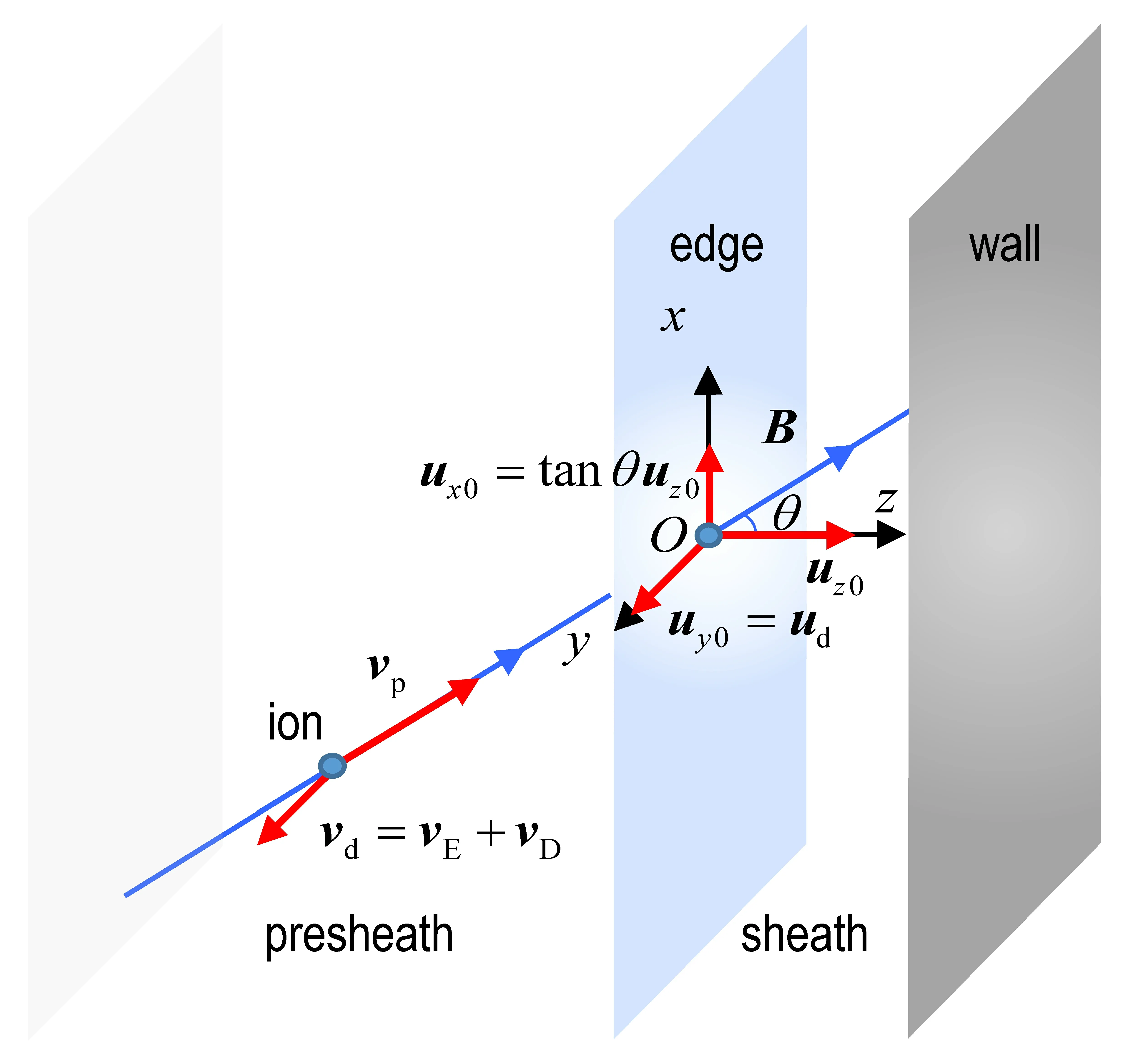
Figure 3.Diagram illustrating the motion of ions in the presheath and their macroscopic velocity at the sheath edge.
Applying the operator d/dΦ to equation (24) and taking the value at the sheath edge,we can directly obtain:
Next,we start with equations (25) and (28) to solve for(dNi/dΦ)0.First of all,applying the operator d/dζ to equation (25),we have:
Substituting the above equation into equation (28),we can derive:
By the chain rule,we have:
Considering equations (23),(32),(38),and (42),the value of the above equation at the sheath edge is:
Applying the operator d/dζ to equation (46),we have:
whose value at the sheath edge is:
By applying the operator d/dζ to equation (30) twice,we have:
From equations (23),(31),and (32),we have:
Substituting the above two equations back into equation(51),we have:
Substituting the above equation back into equation (49),we then have:
So far,we have obtained the expression of (dNi/dΦ)0.Substituting equations (45) and (57) into equation (44),and considering the case of,we can derive:
which is the expression of ion Bohm velocity of the magnetized sheath considering ion stress.Accordingly,the ion Bohm velocity is represented bywhen considering only ion thermal pressure,and byMi=cosθ when neglecting ion stress.Figures 4(a) and (b) show the ion Bohm velocity as a function of ion temperature and collision frequency in these three cases,respectively.It can be observed that the ion stress significantly enhances the ion Bohm velocity.For the unmagnetized plasma sheath with cold ions,the ion Bohm velocity is further reduced toMi=1[43].
In the numerical calculation,we take:
then equation (57) becomes:
From equation (46) and the chain rule,it is not difficult to obtain:
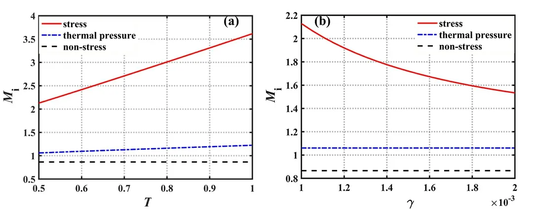
Figure 4.(a) The ion Bohm velocity as a function of ion temperature among the three cases for E0=0.01 ,Ω=0.0125 ,θ=30°,and γ=0.001 ,(b) the ion Bohm velocity as a function of collision frequency among the three cases for E0=0.01 ,Ω=0.0125 ,θ=30°,and T =0.5.
Accordingly,from equations (40) and (41),we have:
3.3.Wall floating potential
The wall floating potential Φwis an important parameter of the steady-state plasma sheath.The numerical solution domain can be determined by solving Φw,and then the sheath thickness ζwcan be obtained.When the sheath reaches a steady state,thez-components of ion and electron fluxes at the wall should be equal:
Considering equations (9) and (59),we have:
In this work,we assume that the wall absorbs electrons without emitting them,so the electron velocity at the wall can be considered to follow a truncated Maxwell distribution:
wheremeis the electron mass andnew=ne0exp(eφw/Te) is the electron density at the wall,we have
Substituting equations (65) and (67) back into equation (64),the wall floating potential can be derived:
It can be observed that,for a specific type of ion,the wall floating potential is only related to the ion Bohm velocity.
4.Numerical simulation
4.1.Potential and particle density
To investigate the impact of ion stress,we solved the ODEs for three different cases under the same sheath parameters:considering ion stress,considering only thermal pressure,and not considering ion stress.These cases are referred to as case 1,case 2 and case 3,respectively.Figure 5(a) shows the potential profiles among the three cases,respectively.It can be observed that in all three cases,the overall trend of the electric potential in the direction normal to the wall is similar,with a relatively gradual decrease near the sheath edge and a rapid drop near the wall.The wall floating potential decreases in the order of the three cases,consistent with the ion Bohm velocity shown in figure 4.This is because the wall floating potential is only related to the ion Bohm velocity,as shown in equation (68).Figure 5(b) depicts the profiles of electric field in the three cases.It can be observed that the electric field profile is opposite to that of the potential.The electric field strength is weaker at the sheath boundary and increases rapidly near the wall,showing an overall upward trend.Additionally,the sheath thickness increases in the order of the three cases,and the sheath thickness in case 1 is significantly smaller than those in case 2 and case 3,which will be explained in figure 6.
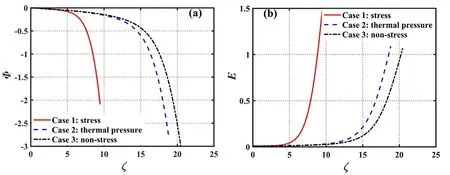
Figure 5.(a) The potential profiles and (b) the electric field profiles among the three cases,for E0=0.01 ,Ω=0.0125 ,T =0.5 ,θ=30°,and γ=1×10⁻³.
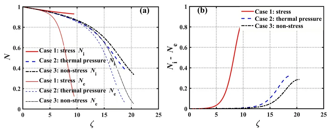
Figure 6.(a) The particle density profiles and (b) the net space charge density profiles among the three cases,for E0=0.01 ,Ω=0.0125,T =0.5 ,θ=30° ,and γ=1×10⁻³.
Figure 6(a) shows the electron and ion density profiles among the three cases.It can be observed that,in the direction normal to the wall,both ion density and electron density decrease in all three cases,with ion density consistently higher than electron density in each case.Additionally,it can be observed that the particle density profiles between case 2 and case 3 are similar.In contrast,the electron density decays more rapidly in case 1,while the ion density decays more slowly.To explain the higher ion density profile in case 1,we first examine the impact of ion stress on ion velocityuz.Equation (28) describes the motion of ions in thez-direction in case 1.On the right-hand side,each term represents the electric field force,magnetic field force,thermal pressure force,and viscous force,respectively,which we will denote asf1,f2,f3,andf4in sequence.We have calculated the profiles of these forces as well as their resultant force Σfwithin the sheath region,and the results are shown in figure 7.As observed,the forces accelerating ion motion are the electric field forcef1and the thermal pressure forcef3,while the forces hindering ion motion are the magnetic field forcef2and the viscous forcef4.The resultant force acting on the ions Σfremains positive,and it rapidly decreases in the direction normal to the wall.Consequently,ions experience continuous acceleration in thezdirection,with the acceleration diminishing as they approach the wall.The magnitudes off1andf4are comparable and significantly larger than those off2,f3,and Σf.Thus,in case 1,the dominant forces responsible for ion acceleration and deceleration are the electric field force and the viscous force,respectively.The presence of the latter greatly diminishes the ion’s acceleration in thez-direction,particularly as it approaches the wall.From duz/dζ =Σf/uzand equation(46),it follows that.In the direction normal to the wall,the ion velocityuzincreases monotonically while the ion density decreases monotonically.Combining this with the profile of Σfwithin the sheath,it can be inferred that the ion density gradient |dNi/dζ| rapidly decreases near the wall and its magnitude is smaller compared to Σf.Therefore,looking at the overall scenario in case 1,the ion density reduction is extremely gradual.For the sudden drop in electron density within the sheath region,we can explain it through the Boltzmann relation it satisfies.By applying the operator d/dζ to equation (24),we have dNe/dζ=-NeE.Due to the electric field strength in the sheath model considering that ion stress (case 1) is higher compared to the other two cases (as noted in figure 5(b)),the electron density gradient |dNe/dζ| in case 1 is larger.This,in turn,contributes to a faster decay in electron density.
Figure 6(b) shows the profiles of net space charge densityNi-Neamong the three cases.It can be seen thatNi-Nein case 1 is significantly higher than those in case 2 and case 3.Due to the higher net charge density,a stronger electric field is generated,which quickly screens the negative potential at the floating wall.As a result,the electric field strength in case 1 is significantly higher compared to case 2 and case 3.Conversely,the sheath thickness in case 1 is much smaller than those in case 2 and case 3.This observation is consistent with the computed results shown in figure 5.
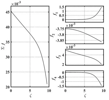
Figure 7.Forces acting on ions in case 1 for E0=0.01 ,Ω=0.0125,T =0.5 ,θ=30° ,and γ=1×10⁻³.
Figure 8 illustrates the ion velocity profiles in the three cases.As evident from figure 8(a),in case 1,the ion velocity increases very gradually in the direction normal to the wall.Conversely,in case 2 and case 3,the increase is rapid.This has been discussed earlier in figure 7.Furthermore,it can be observed that the ion entry velocityuz0into the sheath decreases successively across the three cases,which aligns well with the computational results in figure 4.As indicated by equation (62),it can be deduced that the initial ion velocitiesux0in the three cases should satisfy the same relationship asuz0,which aligns with the description in figure 8(c).From figure 8(b),it is evident that in case 1,the ion entry velocity into the sheathuy0is equal to that in case 2 and greater than that in case 3.This is due to the fact that both case 1 and case 2 take into account the ion thermal pressure.Therefore,in addition to the electric drift velocity,they also consider the ion diamagnetic drift velocity at the sheath boundary.From figures 8(b) and (c),it can be observed that the variations in ion velocitiesuxanduyexhibit similar trends for all three cases,unlike the notable discrepancy inuz.This behavior can be explained by solving the ion momentum equations in thexandy-directions,as given by equations (26) and (27).Through the discussion on the forces acting on ions in thez-direction,it is evident that among the forces experienced by ions,the influences of magnetic and thermal pressure forces on ion motion are minor,while the primary influencing factors are electric field and viscous forces.The viscosity coefficients in thexandydirections,H1=40,are much smaller than the viscosity coefficient in thez-direction,H2=480.Consequently,in comparison to thez-direction,the effect of viscosity on ion motion in thexandy-directions is relatively weak,resulting in similar ion acceleration processes among the three cases.From figure 8(d),it can be observed that the profiles of ion total velocityuamong the three cases is similar to that ofuz.This is due to the fact thatuzis significantly larger thanuxanduyoverall,and it plays a dominant role in the total velocityu.
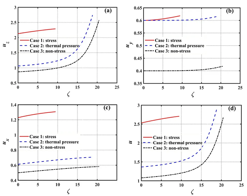
Figure 8.The ion velocity profiles among the three cases for E0=0.01 ,Ω=0.0125 ,T =0.5 ,θ=30° ,and γ=1×10⁻³.
Lastly,we calculated the ion flux Γiw=niwviwat the wall for the three cases,whereniw=n0Niwandviw=csuiwrepresent the ion density and velocity at the wall,respectively.The results are presented in table 1,with the ion flux expressed in unit of 1023m-2s-1.It can be observed that the ion fluxes Γixw,Γiyw,Γizwand Γiwfor the three cases decrease sequentially.This indicates that both ion stress and thermal pressure enhance the ion flux at the wall,with the former exerting a more pronounced influence.
In summary,ion stress significantly reduces the sheath thickness,elevates the wall floating potential,increases the ion Bohm velocity,and augments the ion flux at the wall surface.Additionally,it accelerates the decay of electron density within the sheath,while retarding the decay of ion density and the acceleration of ions within the sheath.Furthermore,the ion thermal pressure has effects on the sheath that are similar to the ion stress in many aspects.For example,it can reduce the sheath thickness to some extent and enhance the ion Bohm velocity,wall floating potential and ion flux at wall.However,ion thermal pressure does not change the profiles of the potential,the electric field,theparticle density and the ion velocity obviously,and its influence on the sheath is far less than that of ion stress.As mentioned above,ion stress is actually the composition of ion viscous stress and thermal pressure,so it can be inferred that the dominant component affecting the sheath is viscous stress,which should not be ignored in the studies on magnetized plasma sheath.
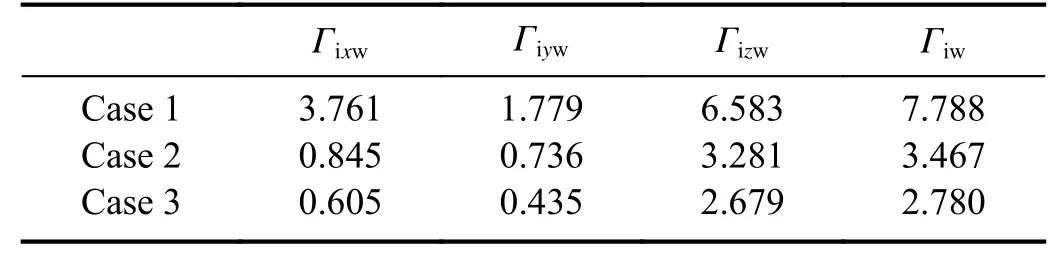
Table 1.Ion fluxes at the wall among the three cases for E0=0.01,Ω=0.0125 ,T =0.5 ,θ=30° ,and γ=1×10⁻³.
4.2.Sheath thickness and wall floating potential
A more detailed investigation is conducted to study the impact of the two distinct ion viscous stresses,ion shear and bulk viscous stresses,on the sheath structure by studying the variations in sheath thickness and wall floating potential.
Figure 9(a) shows the sheath thickness as a function of ion temperature and the magnetic field strength.From the graph,it can be observed that as the value ofTincreases and Ωdecreases,which corresponds to an increase in the viscosity coefficient H1=T/Ω ,the sheath thickness ζwslightly increases.Figure 9(b) illustrates the variation of the sheath thickness with ion temperature and collision frequency.From the figure,it can be observed that asTincreases and γ decreases,corresponding to an increase in the viscosity coefficient H2=0.96T/γ,the sheath thickness gradually decreases.As mentioned earlier,the viscosity coefficients H1and H2respectively characterize the influential strength of ion shear and bulk viscous stresses.Therefore,it can be inferred that the presence of ion shear viscous stress causes the sheath to thicken,while the presence of ion bulk viscous stress causes the sheath to thin.
Figure 10(a) depicts the variation of wall floating potential with ion temperature and magnetic field strength.It can be observed that the wall floating potential Φwincreases only with the increase ofTand does not change with Ω.This is because the wall floating potential is solely related to the ion Bohm velocity,while the latter is independent of the magnetic field strength,as discussed in equations (58) and(68).Overall,as the shear viscosity coefficient H1increases,the wall floating potential slightly increases.Figure 10(b)depicts the variation of the wall floating potential with ion temperature and collision frequency.It can be observed that asTincreases and γ decreases,i.e.,in the direction of increasing the bulk viscosity coefficient H2,the wall floating potential continuously increases.Consequently,it is concluded that both the ion shear and bulk viscous stresses contribute to an increase in the wall floating potential.Considering equation (68),it is not difficult to infer that these two viscous stresses have similar effects on the ion Bohm velocity as they do on the wall floating potential.
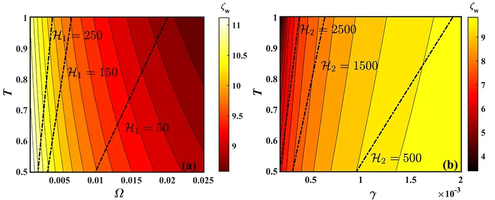
Figure 9.(a) The sheath thickness as a function of ion temperature and the magnetic field strength for E0=0.01 ,γ=1×10⁻³ ,and θ=30°,(b) the sheath thickness as a function of ion temperature and collision frequency for E0=0.01 ,Ω=0.0125 ,and θ=30°.
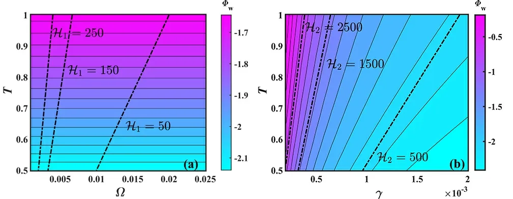
Figure 10.(a) The wall floating potential as a function of ion temperature and magnetic field strength for E0=0.01 ,γ=1×10⁻³,and θ=30° ,and (b) the wall floating potential as a function of ion temperature and collision frequency for E0=0.01 ,Ω=0.0125 ,and θ=30°.
Since,in this work,the bulk viscosity coefficient H2is much larger than the shear viscosity coefficient H1,the dominant effect on the sheath thickness is caused by the ion bulk viscous stress.Its presence leads to a significantly thinner sheath compared to the case without considering ion viscosity,which is consistent with the conclusion obtained from figure 5.Similarly,the contribution to the increase in the wall floating potential and ion Bohm velocity should also be primarily attributed to the ion bulk viscous stress.
5.Conclusions
In this work,a fluid model of magnetized plasma sheath in a 1D3V domain is established to systematically study the effects of the ion stress and its components on the properties of the sheath.The findings indicate that ion stress significantly diminishes the sheath thickness,amplifies ion Bohm velocity,elevates wall floating potential,and augments ion flux at the wall.Furthermore,it expedites the decay of electron density,while decelerating the decay of ion density and the acceleration of ions within the sheath.The dominant component of ion stress affecting the sheath is ion viscous stress.Further study indicates that the ion shear viscous stress causes the sheath thickness,wall floating potential,and ion Bohm velocity to increase slightly,whereas the ion bulk viscous stress contributes to a great reduction in the sheath thickness and significantly increases the wall floating potential and ion Bohm velocity.It is concluded that among the ion stress,the most significant influence on the properties of the magnetized plasma sheath is exerted by the ion bulk viscous stress.
Acknowledgments
This work is supported by National Natural Science Foundation of China (Nos.11975062 and 11605021) and the Fundamental Research Funds for the Central Universities (No.3132023192).
猜你喜欢
风流一代·青春(2021年9期)2021-09-23
疯狂英语·新阅版(2021年6期)2021-07-19
测控技术(2018年4期)2018-11-25
当代教育(2018年4期)2018-01-23
教师·下(2017年10期)2017-12-10
教育教学论坛(2017年40期)2017-10-26
电信科学(2017年6期)2017-07-01
数学年刊A辑(中文版)(2015年3期)2015-10-30
美与时代·美术学刊(2015年10期)2015-05-30
应用数学与计算数学学报(2014年3期)2014-09-26
 Plasma Science and Technology2024年2期
- Plasma Science and Technology的其它文章
- Phase field model for electric-thermal coupled discharge breakdown of polyimide nanocomposites under high frequency electrical stress
- Characteristics of laser-induced breakdown spectroscopy of liquid slag
- Airfoil friction drag reduction based on grid-type and super-dense array plasma actuators
- Non-thermal atmospheric-pressure positive pulsating corona discharge in degradation of textile dye Reactive Blue 19 enhanced by Bi2O3 catalyst
- The characteristics of negative corona discharge and radio interference at different altitudes based on coaxial wire-cylinder gap
- Experimental study on the effect of H2O and O2 on the degradation of SF6 by pulsed dielectric barrier discharge