
Enhanced resonance frequency in Co2FeAl thin film with different thicknesses grown on flexible graphene substrate
2024-03-25 09:30CaiZhou周偲ShaokangYuan袁少康DengyuZhu朱登玉YumingBai白宇明TaoWang王韬FufuLiu刘福福LuluPan潘禄禄CunfangFeng冯存芳BohanZhang张博涵DapingHe何大平andShengxiangWang汪胜祥
Chinese Physics B 2024年3期
Cai Zhou(周偲), Shaokang Yuan(袁少康), Dengyu Zhu(朱登玉), Yuming Bai(白宇明), Tao Wang(王韬),Fufu Liu(刘福福), Lulu Pan(潘禄禄), Cunfang Feng(冯存芳), Bohan Zhang(张博涵),†,Daping He(何大平), and Shengxiang Wang(汪胜祥),‡
1Hubei Engineering and Technology Research Center for Functional Fiber Fabrication and Testing,Wuhan Textile University,Wuhan 430200,China
2School of Electronic and Electrical Engineering,Wuhan Textile University,Wuhan 430200,China
3School of Mathematical and Physical Sciences,Wuhan Textile University,Wuhan 430200,China
4School of Integrated Circuits,Huazhong University of Science and Technology,Wuhan 430074,China
5Key Laboratory for Magnetism and Magnetic Materials,Ministry of Education,Lanzhou University,Lanzhou 730000,China
6Beijing National Center for Condensed Matter Physics and Institute of Physics,Chinese Academy of Sciences,Beijing 100190,China
7Hubei Engineering Research Center of RF-Microwave Technology and Application,Wuhan University of Technology,Wuhan 430070,China
Keywords: enhanced resonance frequency,magnetic resonance field,flexible graphene substrate
1.Introduction
Recently,with improvement in the standard of living,the flexible electronic devices have received wide attention owing to perfect stretchability, low cost, biocompatibility, and light weight,which have great potential in application of sensitive skin,flexible circuit boards,and paper-like displays.In these flexible materials, the advanced carbon material-based films,including carbon fibers,[1]carbon nanotubes,[2-4]multishelled fullerenes,[5,6]and especially graphene,[7,8]exhibit more favorable properties than most rigid substrates in flexibility,weight saving,mechanical reliability,and excellent environmental toughness.The flexible graphene films can be extensively explored in high frequency devices due to the unique mechanical properties.[9-11]He’s group has reported flexible graphene films for radio-frequency antennas, multi-beam radiation, highly sensitive wearable sensor, etc.[12-14]In fact,the graphene film as flexible substrate is expected to Heusler metallic materials are considered to be ideal compounds as high spin polarized current sources, and some of them generally have a high Curie temperature, high spin polarization and low damping,[15,16]Among the Heusler metallic materials, with the formula ofX2YZ(whereXis a transition metal element,Yis another transition metal element, andZis a main group sp element),particularly Co2FeAl(CFA),have attracted intense research interest due to the half-metals even at room temperature.[17-19]Belmeguenai’s research group have investigated the static and dynamic magnetic property in CFA thin films by sputtering on Si and MgO substrates annealed at different temperatures.[20]Our group has reported the electric field tuning magnetic anisotropy in CFA thin film grown on PMN-PT substrate.[21,22]In these cases,the CFA thin film was fabricated on the above conventional rigid substrate.This greatly limits the application scope of flexible thin film materials.Therefore,it is essential to study the magnetic properties of magnetic thin films fabricated on flexible substrate.In this work,the high frequency property of CFA thin film with different thicknesses grown on flexible graphene substrate(FGS)is analyzed in detail at room temperature.With the thickness of CFA thin film grown on FGS varying from 20 nm to 200 nm,the increase of grain size can be obtained.The in-plane magnetic anisotropy field decreases with increasing the thickness of CFA thin film from 20 nm to 100 nm measured by ferromagnetic resonance,which can be attributed to the change of structure of CFA thin film with different thicknesses grown on FGS.However, in-plane magnetic anisotropy field increases with continuing to increase thickness to 200 nm, which can lead to the resonance frequency shifting to higher frequency measured by using a vector network analyzer with the microstrip method.
2.Experimental details
The CFA thin films with different thicknesses (20 nm,50 nm, 100 nm, 150 nm, and 200 nm) were deposited by direct current(DC)magnetron sputtering on FGS at a common base pressure<8×10⁻⁴Pa and work processing Ar pressure of 0.1 Pa, a power of 150 W.A field emission scanning electron microscope(SEM,Hitachi SU5000)was employed to observe the cross-section microstructures and the surface morphologies.The x-ray diffraction (XRD) measurements were performed on X’Pert x-ray powder diffractometer with CuKαradiation (1.54056 °A).The ferromagnetic resonance (FMR)measurements were carried out with a PNA 8722ES vector network analyzer using the coplanar waveguide method.Permeability spectra were carried out with a PNA E8363B vector network analyzer using the microstrip method.
3.Results and discussion
The cross-sectional and highly magnified SEM images of the FGS show that the film based on orderly stacked graphene layers with a thickness of 108µm as shown in Figs.1(b)and 1(c).The cross-section image of CFA thin film with different thicknesses grown on FGS is also observed by SEM.For brevity, only the 200 nm-thick CFA grown on FGS is shown in Fig.1(a).The columnar structure of CFA can be obviously observed,which is comparable to the sample grown on Si substrate.[23,24]The exciting finding lays the foundation for the good quality of CFA/FGS structure.In addition, surface morphologies of the CFA/FGS structure with various thicknesses are shown in the inset of Fig.2(b).Firstly,the smooth surface morphologies of FGS can be obtained as shown in the top inset of Fig.2(b).Then,we can observe that with increasing thickness of CFA thin film,the grain continues growth and corresponding size becomes larger.This result indicates thickness has a great influence on microstructure of CFA thin film grown on FGS.
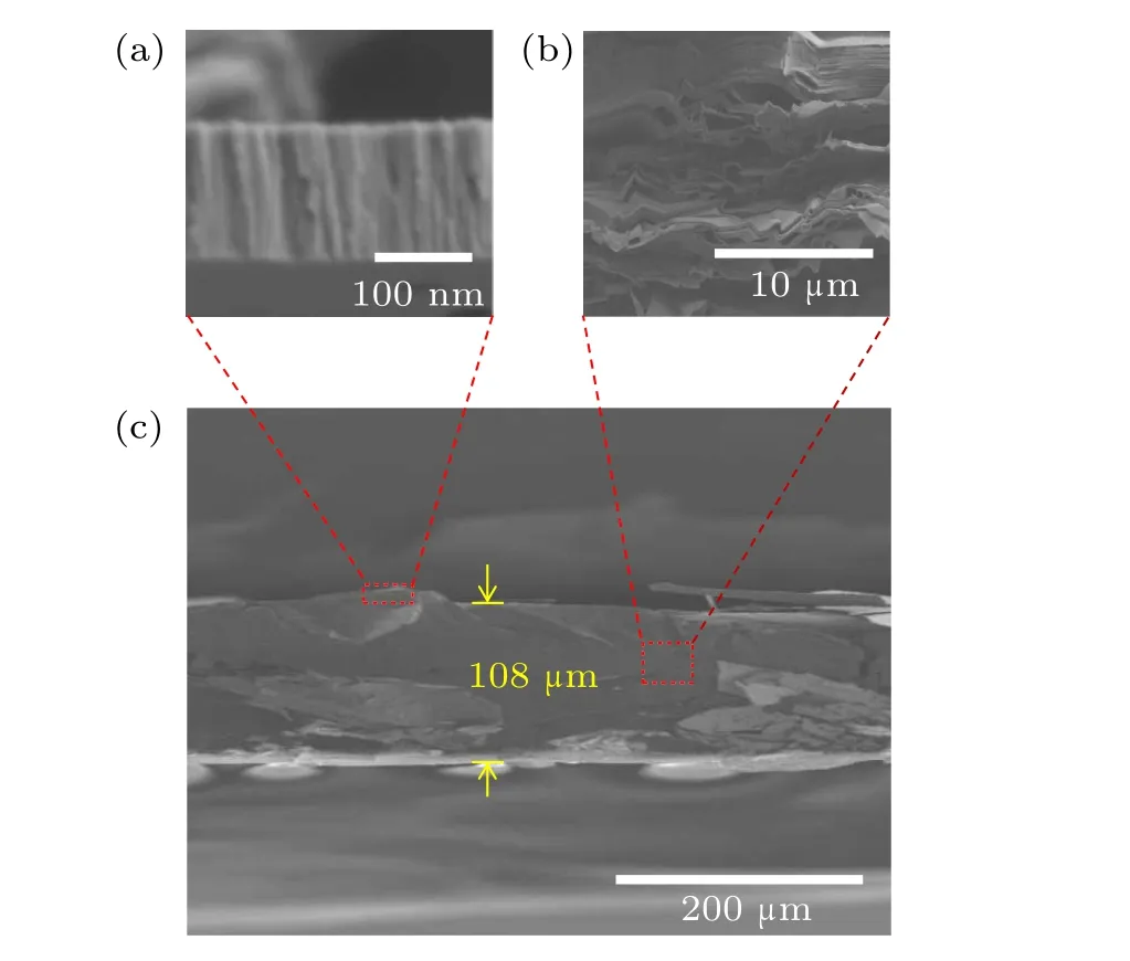
Fig.1.The SEM cross-section images of(a)CFA thin film,(b)FGS and(c)CFA/FGS structure,respectively.

Fig.2.(a)XRD patterns of CFA/FGS structure with different thicknesses of CFA thin film and(0 nm)pure graphene substrate.The inset shows digital photograph of FGS.(b)The grain size versus thickness of CFA thin film.The inset images show surface morphologies of CFA/FGS structure with different thicknesses and FGS.
A piece of rolled FGS is shown in the inset of Fig.2(a),which demonstrates FGS has good flexibility.The crystal structures for all thin films were measured by XRD as shown in Fig.2(a).The sharp diffraction peak(002)and peak(004)of FGS are located at 26.3°and 54.5°.The(022)peak of CFA thin film appears at 44.7°.Moreover, the intensity of (022)peak of CFA thin film increases with increasing thickness of CFA thin film as shown in the top inset of Fig.2(a),which indicates the enhancement of crystallization.However, the position of(022)peak of CFA thin film remains unchanged.According to the Scherrer equation,grain sizes of CFA thin films are 28.6 nm,29.7 nm,31.1 nm,31.8 nm and 34.2 nm with increasing thickness of CFA thin films,respectively,as shown in Fig.2(b), which is consistent with variation tendency of surface morphologies measured by SEM as shown in the inset of Fig.2(b).The increase of grain size with increasing thickness of CFA thin film can indirectly influence the change of in-plane magnetic anisotropy field.The above results confirm the good quality of CFA/FGS structure we prepared, which has huge impact on the physical properties, especially highfrequency magnetic properties.

Fig.3.(a)The schematic illustration of ferromagnetic resonance(FMR)using a vector network analyzer.(b)These curves under unfolded state,and after being fold twenty cycles and twenty-fifth cycles.The top inset shows more cracks with increasing folding cycles.The bottom inset shows the folding schematic diagram.(c)The experimental data(dots)and fitting curves(lines)of FMR for 150 nm-thick CFA thin film.The inset shows the device schematic of microstrip method.(d) The applied microwave frequency versus resonance magnetic field with different thicknesses of CFA thin film.
The high-frequency magnetic properties of CFA thin films were measured by ferromagnetic resonance(FMR)using a vector network analyzer with coplanar waveguide method as shown in Fig.3(a) and the top inset of Fig.3(c).In order to prove the good flexibility of graphene film and the stability of high frequency magnetic property of Co2FeAl thin film grown on flexible graphene substrate, we choose the sample with 150-nm thick CFA thin film to fold over twenty cycles and then take FMR measurement at fixed 10 GHz every five cycles.The folding schematic diagram is shown in the bottom inset of Fig.3(b).As shown in Fig.3(b),the curves basically remain unchanged within twenty cycles.The resonance magnetic field of approximately 875 Oe is obtained by fitting these curves according to Eq.(1).However, the dramatic change of the FMR curve occurs in folding twenty-fifth cycles.The shape of curve becomes slightly shaking and the curve deforms, which indicates the quality of CFA thin film deteriorates after being folded twenty cycles.The more cracks can be distinctly observed after twenty cycles as shown in the top inset of Fig.3(b), which can be measured by RX50M series metallurgical microscope.The similar result can be obtained for CFA thin film with 20 nm, 50 nm, 100 nm and 200 nm.Figure 3(c)shows under different frequencies the typical FMR spectra for 150 nm-thick CFA thin film.In general,the magnetization is probed using a special phase correlation under the microwave excitation, and the FMR spectrum does not correspond to the imaginary part of the susceptibility alone, but in fact represents a mixture of the imaginary and real parts.Therefore, the actual function of the absorption curve can be fitted by an asymmetric Lorentzian function[25]
whereHis the external magnetic field,Hris the magnetic resonance field, ΔHis the half-width at half-maximum of the linewidth,δis the phase that mixes the real and imaginary parts of the dynamic susceptibility,andAis the integral coefficient.The fitting solid curve is shown in Fig.3(c) in light gray color.The fitting result reveals thatHrshifts towards higher magnetic field with increasing frequency.For 150 nmthick CFA thin film, the resonance magnetic field increases from 0.258 kOe to 1.268 kOe with the microwave frequency increasing from 6 GHz to 12 GHz as shown in Fig.3(c).In addition, frequency-dependentφ(H) curves were measured for all thin films.As a result, the data of frequency-dependentHrunder different thicknesses of CFA thin film are shown in Fig.3(d),which is fitted using the Kittel’s equation[26]
where gyromagnetic ratioγ/2π=2.8 GHz/kOe,[27,28]4πMsis the saturation magnetization,andHkis the in-plane magnetic uniaxial anisotropy field.The data of frequency-dependentHrwas fitted using Eq.(2) to extract 4πMsandHk.The fitting curve is shown in Fig.3(d) with red color.With increasing thickness of CFA thin film, the value of 4πMsis almost unchanged.However,Hkis found to decrease from 0.243 kOe to 0.062 kOe with increasing thickness from 20 nm to 100 nm as shown in Fig.4(a).This can be explained as follows.The crystallization of CFA thin film is enhanced with the increase of thickness of CFA thin film as shown in the inset of Fig.2(b).Meanwhile, the grain size becomes larger.The competition between uniaxial magnetic anisotropy and magnetocrystalline anisotropy can appear, which can lead to the decrease of inplane magnetic uniaxial anisotropy field.Nevertheless,Hkincreases from 0.134 kOe to 0.180 kOe with thicknesses increasing from 150 nm to 200 nm.The sudden increase inHkfor CFA thin film with 150 nm-thick can be attributed to releasing of substrate induced strain,[29]which can lead to the higher resonance frequency.
The dependence of permeability on the frequency with different thicknesses of CFA thin film was measured using a vector network analyzer with the microstrip method,as shown in the bottom inset of Fig.4(b).When the thickness of CFA thin film is less than 100 nm, there is no resonance peak detected in this method,which can be attributed to the disorderly arrangement of magnetic moment.This is related to roughness of surface morphologies.With continuing to increase the thickness of CFA thin film, the resonance peak can be obviously observed for CFA thin film with 150 nm and 200 nmthick.The resonance frequency enhances from 3.4 GHz to 5.6 GHz, which is consistent with the result ofHk-dependent thickness of CFA thin film.Moreover,the resonance magnetic field and resonance frequency are quite stable though folded over ten times, which demonstrates that good flexibility of graphene film and the ultrastability of high frequency property of CFA thin film grown on FGS.
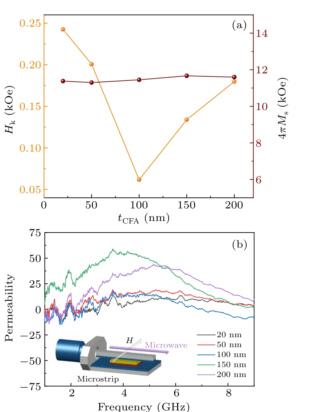
Fig.4.(a)The change of Hk and 4πMswith different thicknesses of CFA thin film.(b)The permeability spectra of CFA thin film.The inset shows the device schematic of coplanar waveguide method.
4.Conclusion
In summary, we identified characteristics of CFA/FGS structure and high frequency magnetic property of CFA thin film with different thicknesses grown on FGS.With increasing thickness of CFA thin film,the surface becomes smoother,and grain size gradually increases,which can influence the change of in-plane magnetic anisotropy field.The in-plane magnetic anisotropy field gradually decreases when the thickness of CFA thin film increases from 20 nm to 100 nm by measurement of FMR.However,with thickness increasing to 100 nm,in-plane magnetic anisotropy field suddenly increases.The measurement result of the dependence of permeability on the frequency demonstrates that the resonance peak can be obviously observed at 3.4 GHz and 5.6 GHz with thickness 150 nm and 200 nm, which is in agreement with the result of FMR.Moreover,the high frequency parameter remains stable though folded over twenty cycles,which indicates the good flexibility of graphene film and the ultrastability of high frequency property of CFA thin film grown on FGS.These results can be used to remove the obstacles that communication system transmission distance and signal quality.
Acknowledgments
Project supported by the National Natural Science Foundation of China (Grant Nos.51901163 and 12104171) and the Fundamental Research Funds for the Central Universities(Grant No.2021XXJS025).
猜你喜欢
党员生活(2023年1期)2023-05-30
数学大王·趣味逻辑(2022年12期)2022-12-11
Chinese Physics B(2022年9期)2022-09-24
Chinese Physics B(2021年10期)2021-10-28
小小说月刊(2021年6期)2021-06-10
国际汉学(2020年1期)2020-05-21
经济技术协作信息(2018年30期)2018-11-22
行政法论丛(2018年2期)2018-05-21
人民中国(日文版)(2016年10期)2016-08-23
微型小说选刊(2015年25期)2015-11-17

- Chinese Physics B的其它文章
- Does the Hartman effect exist in triangular barriers
- Quantum geometric tensor and the topological characterization of the extended Su–Schrieffer–Heeger model
- A lightweight symmetric image encryption cryptosystem in wavelet domain based on an improved sine map
- Effects of drive imbalance on the particle emission from a Bose–Einstein condensate in a one-dimensional lattice
- A new quantum key distribution resource allocation and routing optimization scheme
- Coexistence behavior of asymmetric attractors in hyperbolic-type memristive Hopfield neural network and its application in image encryption