
A polarization sensitive interferometer: Delta interferometer
2024-03-25 09:32ChaoQiWei卫超奇JianBinLiu刘建彬YiFeiDong董翼飞YuNongSun孙雨农YuZhou周宇HuaiBinZheng郑淮斌YanYanLiu刘严严XiuShengYan闫秀生FuLiLi李福利andZhuoXu徐卓
Chinese Physics B 2024年3期
Chao-Qi Wei(卫超奇), Jian-Bin Liu(刘建彬),†, Yi-Fei Dong(董翼飞), Yu-Nong Sun(孙雨农),Yu Zhou(周宇), Huai-Bin Zheng(郑淮斌), Yan-Yan Liu(刘严严),Xiu-Sheng Yan(闫秀生), Fu-Li Li(李福利), and Zhuo Xu(徐卓)
1Key Laboratory of Multifunctional Materials and Structures,Ministry of Education&International Center for Dielectric Research,School of Electronic Science and Engineering,Xi’an Jiaotong University,Xi’an 710049,China
2MOE Key Laboratory for Nonequilibrium Synthesis and Modulation of Condensed Matter,Department of Applied Physics,Xi’an Jiaotong University,Xi’an 710049,China
3Science and Technology on Electro-Optical Information Security Control Laboratory,Tianjin 300308,China
Keywords: phase sensitive interferometer,Fresnel formula,first-order interference
1.Introduction
Interferometers have played an essential role in the development of physics, especially optics.For instance, light was first thought to consist of particles.[1]Young’s famous interference experiments confirmed that light instead consists of waves.[2]Later,it was demonstrated that a first-order interference pattern emerges when individual photons are input into a Mach-Zehnder (M-Z) interferometer, which indicated the wave-particle duality of photons.[3]Another example can be found in the Michelson-Morley experiment, which by utilizing light within a Michelson interferometer[4]confirmed that there is no such thing as ether and ultimately paved the way for the development of the theory of special relativity.[5]All currently reported interferometers,such as Young’s double-slit interferometer, the Michelson interferometer, the M-Z interferometer, the Sagnac interferometer, the Fabry-P´erot interferometer and so on,[6]have different schematics.However,they all have one important property in common,which is that the difference of light reflection times between the two interfering paths is even.This property guarantees that the polarizations of these two interfering beams are identical in the observation plane no matter what the input polarization is.In other words,these interferometers are insensitive to the polarization of input light.
In classical electromagnetic theory, it is well known that the reflection of an electric field is dependent on the polarization of the incidental field.[7,8]What happens if the difference between light reflection times of the two interfering paths is odd? Does the visibility of the interference pattern vary as the polarization of the input light changes? In order to answer these questions, we propose a new type of interferometer, in which the difference of light reflection times between the two interfering paths is odd.The simplest interferometer of this type, which is called a Delta interferometer due to it being shaped like the Greek letter Δ, is employed to study how the first-order interference pattern changes as the polarization of the input light varies.
It is noteworthy that the difference of light reflection times between the two interfering light beams in Lloyd’s mirror interferometer is also odd.[9]However, our proposed interferometer is polarization sensitive,but Lloyd’s mirror interferometer is polarization insensitive, i.e., the visibility of the first-order interference pattern in Lloyd’s mirror interferometer is independent of the polarization state of the employed light.Most studies related to interferometers confirm that Lloyd’s mirror interferometer is polarization insensitive.[10-16]The reason why is that Lloyd’s mirror is usually used in the glancing incidence condition, in which the reflection coefficients equal-1 for all polarization states of incidental light.[9]The polarization state of the reflected light beam in Lloyd’s mirror interferometer is the same as the one directly incidental to the observation plane.Theπphase shift due to the reflection will not change the visibility of the first-order interference pattern in Lloyd’s mirror interferometer for different polarization states of the incidental light beam.
Another type of interferometer is called a polarization interferometer.[17-20]The differences between a polarization interferometer and our proposed Delta interferometer are as follows.In a typical polarization interferometer, two orthogonally polarized electric fields are usually employed and the polarization difference is introduced by polarization components, such as a polarizing beam splitter,[19]a quarter waveplate[17]and so on.In a Delta interferometer,the polarizations of the two interfering electric fields are not always orthogonal.The polarization difference between the two interfering electric fields in a Delta interferometer is introduced by the reflection time difference.A more important difference between these two types of interferometers lies in how the interference patterns are obtained.In a polarization interferometer,two orthogonally polarized fields are usually measured after passing a polarizer oriented in 45°[20,21]or measured independently and then the difference between these two measured signals is calculated.[22]While in a Delta interferometer, the two interfering electric fields are combined directly to observe the first-order interference pattern,which is more like an M-Z interferometer than a polarization interferometer.The Delta interferometer provides a perfect tool to study the reflection of an electric field in different polarizations and may find possible applications in polarization-sensitive scenarios,such as the observation of phase objects,[23]polarization-modulated twophoton interference[24]and so on.
The remaining parts of the paper are organized as follows.In Section 2,the Delta interferometer is introduced and its first-order interference pattern is calculated.Section 3 includes experiments to verify the theoretical predictions.The discussions and conclusions are in Sections 4 and 5, respectively.
2.Theory
For comparison,an M-Z interferometer and the modified M-Z interferometer shown in Fig.1 are taken as examples to show the difference between existing interferometers and the proposed Delta interferometer.In the M-Z interferometer shown in Fig.1(a),there are two interfering paths.One is the light transmitting through beam splitter 1 (BS1), reflected by mirror 2(M2)and then reflected by BS2.Light traveling along this path is reflected twice.Light traveling in the other path is reflected by BS1and M1,respectively.The difference of light reflection time between these two paths equals zero,which is an even number.In the modified M-Z interferometer shown in Fig.1(b),the difference of light reflection time between the two interfering paths equals 4,which is also an even number.To the best of our knowledge, the difference of light reflection time between the two interfering paths is even for all the known interferometers, such as Young’s double-slit interferometer,the Michelson interferometer,the M-Z interferometer,the Sagnac interferometer,the Fabry-P´erot interferometer and so on.[6]
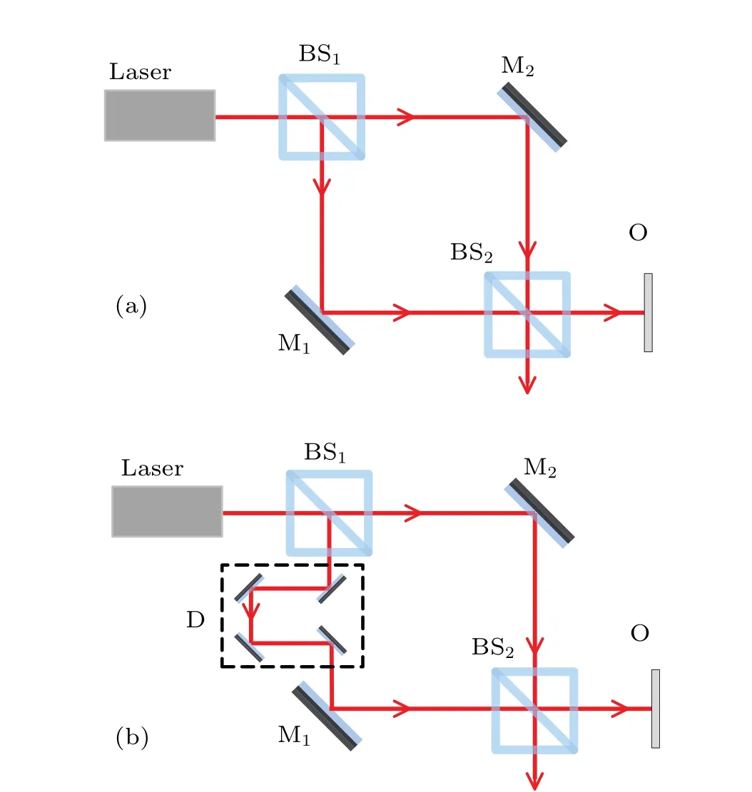
Fig.1.Mach-Zehnder interferometer(a)and modified Mach-Zehnder interferometer (b).The laser is a single-mode continuous-wave laser.BS is a non-polarizing beam splitter.M is a mirror.O is the observation plane.D represents the delay line in the modified Mach-Zehnder interferometer consisting of four mirrors.
Figure 2 shows the scheme of the proposed Delta interferometer.The laser is a single-mode continuous-wave laser.P is a half-wavelength plate employed to control the polarization of laser light.BS is a non-polarizing beam splitter, in which a plate beam splitter instead of a cubic beam splitter is employed.M is a mirror and O is the observation plane.There are two paths for laser light reaching the observation plane.One path is light transmitting through BS1and BS2.The other path is light reflected by BS1, M and BS2, respectively.The difference between the light reflection time in the two interfering paths equals 3,which is an odd number.
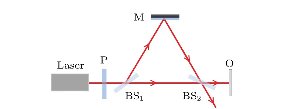
Fig.2.Delta interferometer.The laser is a single-mode continuouswave laser.P is a half-wavelength plate.BS is a non-polarizing beam splitter.M is a mirror.O is the observation plane.
In order to study the first-order interference pattern in the Delta interferometer, one has to take the reflection and transmission in different polarization states into account.We will follow the custom introduced in Ref.[25] to discuss the reflection and transmission of a light field.Figure 3 shows the electric field with arbitrary polarization being incident into a boundary between a medium of refractive indexn0and a medium of refractive indexn1.Any polarized electric field can be divided into the superposition of two orthogonally polarized fields.[7]It is convenient to choose these two orthogonally directions as being parallel and perpendicular to the reflection plane, respectively.EipandEisrepresent the parallel and perpendicular parts of the incident electrical fields,respectively.Erp,Ers,EtpandEtsare defined similarly,in which r and t in the subscript represent reflection and transmission,respectively.θi,θrandθtare the incidental,reflection and transmission angles,respectively.
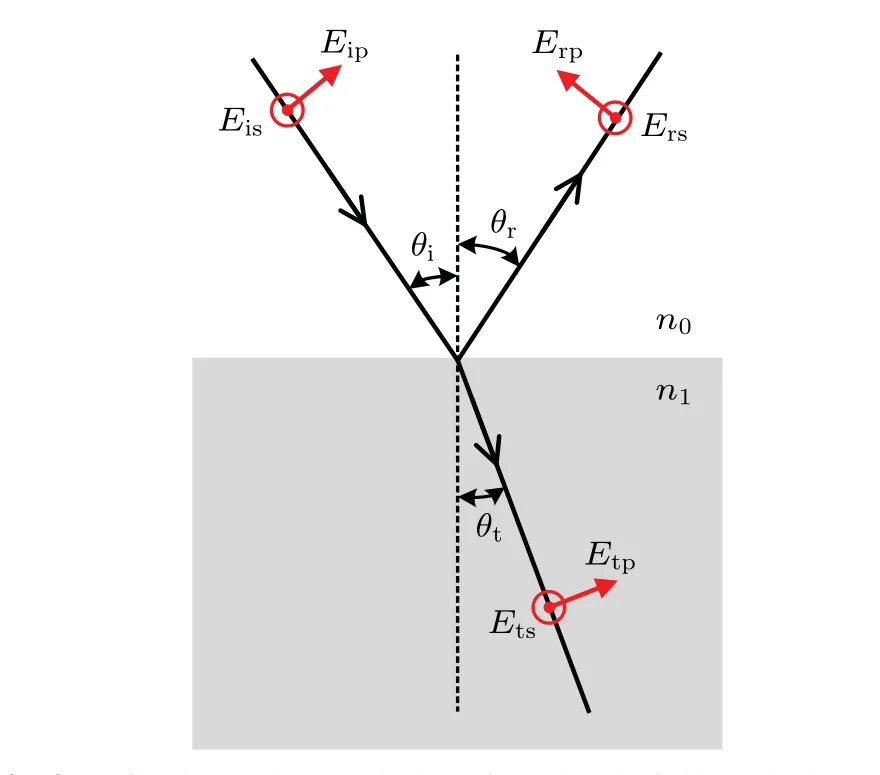
Fig.3.Reflection and transmission of an electric field on the boundary between two mediums. n0 and n1 are the refractive indexes of these two mediums. Eip, Erp and Etp are the incidental, reflected and transmitted electric fields parallel to the reflection plane, respectively. Eis,Ers, and Ets are the incidental, reflected, and transmitted electric fields perpendicular to the reflection plane,respectively. θi,θr and θt are the incidental,reflection and transmission angles,respectively.
The reflection and transmission coefficients of the parallel and perpendicular parts are dependent on the incidental angle,the polarization of the incidental field and the refractive indexes of the media,which can be expressed as[25]
HereRsandRpare the reflection coefficients of perpendicular and parallel components,respectively.TsandTpare the transmission coefficients of perpendicular and parallel components,respectively.The above equations are the well-known Fresnel formula in classical electromagnetic theory.[23,25]
For simplicity, we only consider the linearly polarized light case.The electric field of linearly polarized light emitted by a single-mode continuous-wave laser can be expressed as
whereΦis the phase difference betweenEplandEsl.EplandEslare the electric fields parallel and perpendicular to the reflection plane,respectively.
The electric field in the observation plane is the sum of two components.One component is the field traveling through BS1and BS2(written as path 1 for short),
whereEO1pandEO1sare the parallel and perpendicular components ofEO1, respectively.Tp(BSj) andTs(BSj) are the transmission coefficients of the parallel and perpendicular components for BSj(j=1 and 2),respectively.ωandkare the angular frequency and wave vector of the electric field,respectively.t1is the starting time of electric field in path 1.r1is the position vector along path 1.For simplicity, the laser light is considered as a single frequency in the following calculations.
The other component in the observation plane is the field reflected by BS1,M and BS2(path 2 for short),
where the meanings of all the symbols are similar to the ones in Eq.(3).
Since electric fields with orthogonal polarizations cannot interfere with each other,[23]the intensity of light in the observation plane equals the sum of the parallel and perpendicular parts
where|·|2means modulus square.Substituting Eqs.(3) and(4) into Eq.(5), it is easy to have the first-order interference pattern in the observation plane(see Appendix A for detailed calculations),
where paraxial approximation and one dimension are assumed to simplify the results.The assumptionsRs(M) =-1 andRp(M)=1 for reflection on a silver mirror are employed in the calculation because silver can be approximately treated as an ideal conductor.[8]|Epl|and|Esl|are the amplitudes of the electric field with parallel and perpendicular polarizations,respectively.Tp1is short forTp(BS1)×Tp(BS2).Rp2is short forRp(BS1)×Rp(BS2).Ts1is short forTs(BS1)×Ts(BS2).Rs2is short forRs(BS1)×Rs(BS2).φis the phase difference between the laser electric field att1andt2.B(Δz)is short for cos[ω(t1-t2)]cos[k0(d1-d2)] and Δzis proportional to the light path difference between the two interfering beams.2Δkis the difference betweenk1andk2in the transverse direction.
Equation(6)indicates that the first-order interference pattern of polarized laser light in the Delta interferometer equals the sum of two sets of interference patterns.The periods of these two interference patterns are the same.However, there is aπphase shift between these two sets of interference patterns.The position of the maximum of the first interference pattern coincides with the position of the minimum of the second interference pattern.If|Epl|22Re(Tp1R*p2eiφ) equals|Esl|22Re(Ts1R*s2eiφ),there will be no interference pattern observed even if there is a first-order interference pattern for parallel or perpendicular polarization individually.
3.Experiments
In the last section, we have theoretically calculated the first-order interference pattern of the linearly polarized singlemode continuous-wave laser light in the Delta interferometer.It is found that the visibility of the first-order interference pattern is dependent on the polarization of the incidental laser light.In this section,we will experimentally verify the prediction with linearly polarized laser light.
The experimental setup is shown in Fig.4.A He-Ne laser with a central wavelength of 632.8 nm and frequency bandwidth of 1.5 GHz is employed.A half-wave plate(WP1)combined with a polarizing beam splitter (PBS) is employed to control the intensity of laser light incidental into the Delta interferometer.S is a beam stopper to collect the light transmitting through the PBS.The polarization of the electric field reflected by the PBS is perpendicular to the reflection plane.Another half-wave plate(WP2)is used to control the polarization of the incidental light.BS1and BS2are two non-polarizing 1:1 beam splitters.M is a silver mirror.CA is a circular intensity attenuator to control the intensity of transmitted light in the Delta interferometer.A lens(L)and a CCD camera are employed to record the first-order interference pattern.
As mentioned above, there are two interfering paths in the Delta interferometer.One is reflected by BS1,M,and BS2.The other one is transmitted by BS1and BS2.The observed interference pattern is a result of the superposition of these two light fields.A typical interference pattern in the Delta interferometer is shown in Fig.5.The observed interference pattern is a typical two-beam interference pattern,which is similar to the one observed in Michelson or M-Z interferometers when the angle between the two interfering beams is not zero.

Fig.4.Experimental setup of the Delta interferometer.Laser: singlemode continuous-wave laser.WP: half wavelength plate.PBS: polarizing beam splitter.S: beam stopper.BS: non-polarizing beam splitter.M: silver mirror.CA:circular intensity attenuator.L:lens.CCD:charge-coupled device.

Fig.5.Typical first-order spatial interference pattern observed in the Delta interferometer.
Two groups of interference patterns were measured.The first group was measured by keeping the intensity of the reflected light equal to the one of the transmitted light by tuning the circular intensity attenuator.The calculated visibilities of the observed interference patterns are shown in Fig.6.The empty squares are the calculated visibilities from the observed interference patterns.The blue curve is the theoretical visibility of the interference pattern based on Eq.(6), which is calculated by assumingTp1=Rp2,Ts1=Rs2,φ=0, andB(Δz)=1.With the simplification above,it is straightforward to obtain the relation between the visibility of the interference pattern and the polarization angle of the input laser light(see Appendix B)
whereVECis the calculated visibility of the interference pattern with equal intensities.φis the polarization angle of the input laser light.φis set to be 0 for p polarized light and in the range of(-π/2,π/2].The red curve is the theoretical fitting of the experimental data based on Eq.(7)by adding a parameterαin front of Eq.(7),whereαis in the range of[0,1]and is the visibility of the interference pattern of s or p polarized laser light in the Delta interferometer.
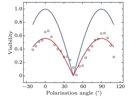
Fig.6.Visibility of the interference pattern with equal intensities vs.polarization angle of 633 nm laser light.The empty squares are experimental results.The blue curve is the theoretical prediction of Eq.(7).The red curve is the theoretical fitting of the experimental data by tuning the visibility.
The second group was measured by keeping the position of the circular intensity attenuator fixed so that the intensities of the two superposed laser light beams are equal when p polarized light is incidental into the interferometer.Due to the transmission and reflection coefficients of the beam splitter being dependent on the polarization angle of the incidental light, the ratio between the intensities of the two interfering light beams changes as the polarization angle of the incidental laser light changes.The red empty circles are the measured ratios between the intensities of the transmitted and reflected laser light beams.The red line connecting the red empty circles serves as a guide for the eye.The black empty squares in Fig.7 are the calculated visibilities of the measured interference pattern in this case.The blue curve is the theoretical visibility of the interference pattern with equal intensities based on Eq.(7).
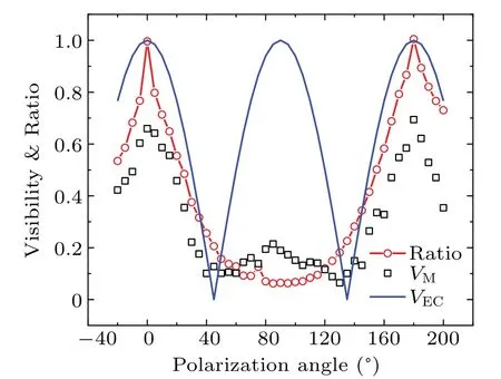
Fig.7.Visibility of the interference pattern with unequal intensities vs.polarization angle of 633 nm laser light.The empty squares are measured visibility of the interference patterns.The empty circles are measured ratios between the intensities of the transmitted and reflected light beams.The blue curve is the theoretical prediction of Eq.(7).Please see the main text for details.
The visibility of the interference pattern in Fig.7 is dependent on the ratio of the superposed laser light beams and the visibility of the interference pattern with equal intensities.When the polarization angle equals 0°,i.e.,the input laser light is p polarized, the observed visibility of the interference pattern gets its maximum value.As the polarization angle increases from 0°to 90°, the ratio between the reflected and transmitted laser light decreases monotonously.However,the visibility of the interference pattern decreases from 0°to 45°and then increases from 45°to 90°.The reason why is that when the polarization angle of the input laser light equals 45°,the visibility of the interference pattern is predicted to be zero,as shown by the blue curve in Fig.7.The observed visibility in this condition is 0.127.As the polarization angle of the input laser light increases from 45°to 90°,the ratio between the intensities of the transmitted and reflected laser light beams continues to decrease,while the visibility of the interference pattern increases.When the polarization angle of the input laser light equals 90°,the ratio equals its minimum,0.064,and the visibility in this condition equals 0.189.As the polarization angle increases from 90°to 180°, the ratio increases and the visibility gets its minimum when the polarization angle equals 135°,which is similar to the one in the 45°case.

Fig.8.Visibility of the interference pattern with equal intensities vs.polarization angle of 780 nm laser light.The empty squares are experimental results.The blue curve is theoretical prediction of Eq.(7).The red curve is the theoretical fitting of the experimental data by tuning the visibility.
The measured visibilities of the interference patterns in Figs.6 and 7 are obviously lower than the theoretical ones.The main reason why is that the path difference between these two interfering beams(~18.2 cm)is at the same level of the coherence length of the employed He-Ne laser (~20 cm).In order to decrease the influence of temporal coherence on the observed interference pattern, a semiconductor laser with central wavelength at 780 nm and a frequency bandwidth of 200 kHz was employed to repeat the experiments above.Figure 8 shows the measured visibilities of the interference patterns of a 780 nm laser in the interferometer by keeping the intensity of the reflected light equal to that of the transmitted light.The empty squares are the measured visibilities of the observed interference patterns.The blue curve is the theoretical visibility of the interference pattern based on Eq.(7).The observed visibility is much larger than the one with a He-Ne laser shown in Fig.6.
Figure 9 shows the measured results with a 780 nm laser with unequal intensities.The red empty circles are the measured ratios between the intensities of the transmitted and reflected laser light beams.The red line connecting the red empty circles serves as a guide for the eye.The black empty squares in Fig.9 are the calculated visibilities of the measured interference pattern in this case.The blue curve is the theoretical visibility of the interference pattern with equal intensities based on Eq.(7).The observed results are similar to the ones in Fig.7 except that better visibility of the interference pattern is observed in the 780 nm laser case.For instance,the minimal visibility equals 0.066 when the polarization angle equals 45°.
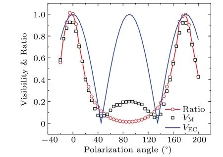
Fig.9.Visibility of the interference pattern with unequal intensities vs.polarization angle of the 780 nm laser light.The empty squares are measured visibility of the interference pattern.The empty circles are measured ratios between the intensities of the transmitted and reflected light beams.The blue curve is the theoretical prediction of Eq.(7).Please see the main text for details.
4.Discussion
In the previous section, we reported that the visibility of the interference pattern in the Delta interferometer changes as the polarization angle of the linearly polarized laser light changes.A simplified theoretical result based on Eq.(7) is employed to interpret the observed results.Even though the tendency of the experimental results and theoretical predictions are consistent,there are some departures between them.In this section, we will discuss why the departures exist and how to decrease them.
The first reason why the experimental results are different from the theoretical predictions is that the employed theoretical simplifications are usually not met in the experiments.For instance,Tp1=Rp2means the overall transmission coefficient of path 1 equals the overall reflection coefficient of path 2 for p polarized light.Ts1=Rs2means that a similar conclusion holds for s polarized light.These two assumptions hold only when the splitting ratio of the two employed beam splitters is 1:1 for both p and s polarized light, and there is no energy loss for transmission and reflection.These conditions cannot be met in real experiments.
The second reason is that the employed non-polarizing beam splitter (Daheng, GCC411112) is made for 45°incidence,which is different from the incidental angle of the beam splitter in the Delta interferometer.Hence the ratio between the intensities of the transmitted and reflected light may be different from the given parameter of the beam splitter.Furthermore,the ratio of the beam splitter being 1:1 is dependent on the polarization angle of the incidental laser light,which is confirmed by the measured ratio between the intensities of the transmitted and reflected laser light shown in Figs.7 and 9.Our theoretical model is based on the splitting ratio of beam splitter being 1:1 and is independent of the polarization angle of the incidental laser light,which is obviously different from the experimental conditions.
The third reason is that the transverse shape of the employed laser light beam is an ellipse when a semiconductor laser is employed.Even though the total intensities of the two superposed laser light beams are equal, the intensities of the superposed two light beams may not be equal at every superposed point.It is the reason why the visibility of the observed interference pattern cannot reach 1 for s or p polarized laser light with equal intensities shown in Fig.8.The maximal visibility observed in our experiments equals 0.95.
The fourth reason is that a silver mirror does not add an exactπphase shift for the reflection of s polarized light due to silver not being ideal conductor.When a 45°linearly polarized laser light beam is incidental into the Delta interferometer,the polarization of the reflected laser light is not 135°linearly polarized, but elliptically polarized.There is a 45°polarized component in the reflected light beam.The visibility of the interference pattern cannot reach 0 for a 45°linearly polarized laser light beam in the Delta interferometer.In fact, the observed visibility equals 0.07 for 45°linearly polarized laser light,as shown in Fig.8.
Based on the results above, it is straightforward to find ways to optimize the Delta interferometer.For instance, the main limitation listed above is the beam splitter.The modified Delta interferometer shown in Fig.10 could be employed to ensure that the incidental angle of laser light on the beam splitter equals 45°while keeping the difference between light reflection times of the two interfering paths odd.In terms of the transverse shape of the laser light, one could change the transverse shape of the semiconductor laser light beam into a Gaussian one with the help of some optical elements.As regards the splitting ratio of the beam splitter being dependent on the polarization angle of the input laser, one may find a type of beam splitter whose splitting ratio is independent of the polarization angle.It is worth noting that only linearly polarized laser light was employed in our experiment.In our future study, circularly and elliptically polarized light will be employed in the Delta interferometer.By considering all the possible polarization states, systematic data of the first-order interference pattern in the Delta interferometer can be built.In order to simplify the process to obtain Eq.(6), some simplifications are employed, which may be reconsidered to obtain more accurate predictions in future research.Once all the mentioned conditions are met,the differences between the theoretical and experimental results can be further decreased.
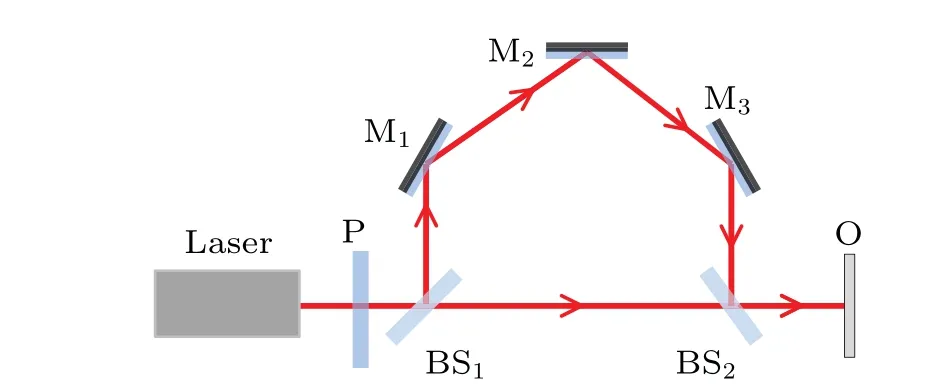
Fig.10.Modified Delta interferometer.Compared with the Delta interferometer shown in Fig.2, there are three mirrors instead of one.The main advantage of the modified Delta interferometer is that the incidental angle of light on BS equals 45°.All the symbols have the same meanings as those in Fig.2.
Figure 11 shows an example of a possible application of the Delta interferometer.OTmeans object for testing.It could be optically active materials or the birefringence of transparent materials under stress,which will change the polarization state of the incidental laser light.Before putting OTin the Delta interferometer, a first-order interference pattern is recorded for comparison.Then another first-order interference pattern is recorded by putting OTin the Delta interferometer as shown in Fig.11.By comparing the obtained interference patterns with the pre-measured results,such as those shown in Figs.8 and 9,one can obtain the polarization change of OTon the incidental laser with the help of the first-order interference pattern.

Fig.11.A possible application of the Delta interferometer.OT means object for testing and the meanings of other symbols are the same as those in Fig.2
5.Conclusions
In conclusion, we have proposed a new type of polarization-sensitive interferometer in which the difference of light reflection times between the two interfering beams is odd.As an example, the Delta interferometer was introduced to study the relationship between visibility of the interference pattern and polarization angle of the input laser light.It was found that visibility of the interference pattern is indeed dependent on the polarization of the incidental laser light,which is different from Michelson or M-Z interferometers.Two groups of interference patterns were measured and a simplified theoretical result was used to interpret the observed results.The experimental results and theoretical predictions were consistent.However, there were some departures.The reasons why the experimental results were different from the theoretical predictions were analyzed and corresponding suggestions to decrease the difference were given.With further improvements,this new type of polarization-sensitive interferometer may serve as a basic optical interferometer in physics, especially for the demonstration of the Fresnel formula.This polarization-sensitive interferometer may also find potential applications in polarization-sensitive application scenarios,such as experiments involving birefringent crystal and so on.
Appendix A:Calculating the first-order interference pattern in the observation plane
We will calculate the results for|EO1p+EO2p|2in detail and the results for|EO1s+EO2s|2can be obtained by analogy,

wherer0is set to be 0 for simplicity and can be done by setting the origin of the coordinate system at the output position of the employed laser light.The first two terms in Eq.(A2)are the constant background in the interference pattern.The last term corresponds to the interference part, which can be further simplified by considering the paraxial approximation in the symmetrical configuration shown in Fig.A1.
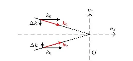
Fig.A1.Symmetrical configuration for the first-order interference. k1 and k2 are the wave vectors in Eq.(A2). k0 and Δk are the longitudinal and transverse components of the wave vector, respectively.O is the observation plane. ez and ex are unit vectors of the longitudinal and transverse direction, respectively.One-dimensional simplification is employed to calculate the transverse part.
With the help of Fig.A1,k1·r1-k2·r2can be simplified as
wherek0and Δkare the longitudinal and transverse components of the wave vector, respectively,djandxjare the longitudinal and transverse components of the position vectorrj(j=1 and 2), respectively,ezandexare the unit vectors in longitudinal and transverse directions, respectively, O is the observation plane.One dimension is assumed in the transverse part.Equation (A3) can be calculated ask0(d1-d2)-Δk(x1+x2).For the first-order interference pattern,x1always equalsx2and will be written asxhereafter.Hence, Eq.(A3)can be simplified ask0(d1-d2)-2Δkx.
Equation(A2)can be simplified as
where cos[ω(t1-t2)]corresponds to the temporal interference,cos[k0(d1-d2)] corresponds to the longitudinal spatial interference, and cos(2Δkx) corresponds to the transverse spatial interference.
By analogy of the results above,|EO1s+EO2s|2can be calculated as
where the plus sign between the constant background and the interference term in Eq.(A4) changes into minus sign in Eq.(A5)due toRp(M)=1 andRs(M)=-1.
The final interference pattern in the observation plane is the sum of these two interference patterns with the same period.However,there is aπphase shift between these two sets of patterns.IfEpl(t1)Tp1E*pl(t2)R*p2equalsEsl(t1)Ts1E*sl(t2)R*s2,there will be no interference pattern observed,even if there are interference patterns for parallel or perpendicular components individually.
For a single-mode continuous-wave laser, the amplitude of electric field does not change with time.|Esl(t1)| equals|Esl(t2)|and|Epl(t1)|equals|Epl(t2)|,which will be written as|Esl| and|Epl|, respectively.Since only the spatial transverse part is studied in our experiments,cos[ω(t1-t2)]cos[k0(d1-d2)]is written asB(Δz)for short,where Δzis proportional to the light path difference between these two interfering light beams.The final first-order interference pattern in the observation plane equals
whereφis the phase difference between the electric field att1andt2.|Epl|2and|Esl|2are the intensities of laser light components with parallel and perpendicular polarizations,respectively.The terms within the square brackets are interference patterns depending on the transmission and reflection coefficients of the beam splitter.Once the incidental angle and beam splitters are determined, the visibility of the interference pattern can be calculated.
By changing the polarization of the incidental laser light,one can change the visibility of the interference pattern.It is different from the first-order interference patterns in usual interferometers, such as Young’s double-slit interferometer,the Michelson interferometer and the M-Z interferometer, in which the first-order interference pattern is independent of the polarization of the incidental light.
Appendix B: Calculating the visibility of the first-order interference pattern
In this section,we will show how to calculate the visibility of the interference pattern in the Delta interferometer based on Eq.(6).For simplicity, we assumeTp1=Rp2,Ts1=Rs2,φ=0,andB(Δz)=1,with which Eq.(6)can be simplified as
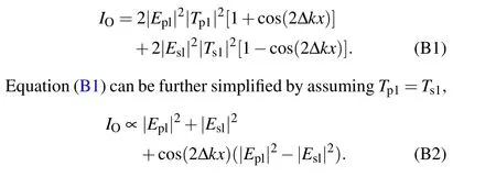
When|Epl|2-|Esl|2is larger than 0,the visibility of the interference pattern can be expressed as
whereIOmaxandIOminare the maximum and minimum intensities of the interference pattern,respectively.With the help of Fig.B1,Eq.(B3)can be simplified as

Fig.B1.The relationship between the polarization angle φ and the perpendicular and parallel electric field components. Esl and Epl are the perpendicular and parallel electric fields,respectively.
With the same method above, it is easy to have the visibility of interference pattern when|Epl|2-|Esl|2is less than 0,
Hence the visibility of the interference pattern in the Delta interferometer shown in Fig.4 equals
where polarization angleφis in the range of(-π/2,π/2].For the polarization angle outside of(-π/2,π/2],one can obtain the visibility based on the periodicity of the triangle function.
Next, we will calculate the visibility of interference pattern in the Delta interferometer for non-ideal conditions, i.e.,the visibility of interference pattern for s or p polarized light is not 100%.Equation(B1)should be re-written as
whereαis the visibility of s or p polarized light in the Delta interferometer and is in the range of[0,1].With the same method above,the visibility of the interference pattern in the Delta interferometer equals
Whenαequals 1,Eq.(B8)becomes identical to Eq.(B6).
Acknowledgements
Project supported by the Shanxi Key Research and Development Project (Grant No.2019ZDLGY09-08) and Shanxi Nature and Science Basic Research Project (Grant No.2019JLP-18).
猜你喜欢
湘潮(上半月)(2023年6期)2023-08-11
作文大王·笑话大王(2022年8期)2022-07-10
作文大王·笑话大王(2022年11期)2022-05-30
小学教学研究(2022年3期)2022-04-08
语数外学习·初中版(2021年11期)2021-09-17
少年博览·小学高年级(2021年6期)2021-08-06
中国现当代社会文化访谈录(2016年0期)2016-09-26
消费者报道(2015年8期)2015-05-30

- Chinese Physics B的其它文章
- Does the Hartman effect exist in triangular barriers
- Quantum geometric tensor and the topological characterization of the extended Su–Schrieffer–Heeger model
- A lightweight symmetric image encryption cryptosystem in wavelet domain based on an improved sine map
- Effects of drive imbalance on the particle emission from a Bose–Einstein condensate in a one-dimensional lattice
- A new quantum key distribution resource allocation and routing optimization scheme
- Coexistence behavior of asymmetric attractors in hyperbolic-type memristive Hopfield neural network and its application in image encryption