
High-order Bragg forward scattering and frequency shift of low-frequency underwater acoustic field by moving rough sea surface
2024-03-25 09:30YaXiaoMo莫亚枭ChaoJinZhang张朝金LiChengLu鹿力成QiHangSun孙启航andLiMa马力
Chinese Physics B 2024年3期
关键词:马力
Ya-Xiao Mo(莫亚枭), Chao-Jin Zhang(张朝金), Li-Cheng Lu(鹿力成),Qi-Hang Sun(孙启航), and Li Ma(马力)
1Key Laboratory of Underwater Acoustic Environment,Institute of Acoustics,Chinese Academy of Sciences(CAS),Beijing 100190,China
2China State Shipbuilding Corporation Systems Engineering Research Institute,Beijing 100094,China
3Little Bird Co.,Ltd,Beijing 100089,China
Keywords: high-order Bragg scattering,frequency shift,low-frequency acoustic field,moving rough sea surface
1.Introduction
As a key component of underwater acoustic waveguide,the undulation of the sea surface induces an evident acoustic scattering modulation, which is an important topic in underwater acoustic research,particularly in the reverberation of active sonar detection.[1]To directly describe the acoustic scattering field, empirical formulas, perturbation theory, Kirchhoff approximation, small-slope approximation methods, and their combined methods have been widely used.[2,3]Moreover,for the sea surface acoustic scattering in underwater acoustic propagation, range-dependent models are effectively established by using parabolic equation methods, ray methods,coupled normal wave methods,and other methods.[4,5]In addition to conventional backscattering, forward scattering has attracted considerable attention with the development of multistatic underwater acoustic detection.[6,7]
Comparing with a static rough sea surface,[8,9]the acoustic scattering modulation effect of a moving rough sea surface has been rarely studied.In theory, the motion of the waveguide boundary produces a Doppler frequency shift.According to the sound field calculation model of moving medium in aeroacoustics,[10,11]the Doppler frequency shift and spectrum expansion of the received signal are not prominent when the sea surface is regard as a context of waveguide medium.This can be explained by the Mach number, which is the ratio of the motion speed of the medium to the speed of sound.Meanwhile, based on the conventional acoustic Doppler frequency shift analysis,[12]the frequency shift depends on the sound frequency and relative speed between the source and receiver.The frequency shift is almost negligible for the lowfrequency acoustic band.
Low-frequency acoustic detection experiments near the coast[13]and simulation calculations[14]have obtained inconsistent frequency modulation effects.Obvious frequency shift and frequency expansion phenomena are observed when lowfrequency acoustic waves are scattered by a moving rough sea surface.According to the results of frequency modulation,the rough sea surface moving in the acoustic field cannot be simply equated with the relative motion of the medium or sound source-receiver.Instead, it should be similar to “grating” to form the Bragg scattering phenomenon and modulate the frequency of the acoustic scattering field.The Bragg scattering process of a sea surface is equivalent to the Fourier series expansion of the sea surface period under the Rayleigh assumption.[15,16]Compared with limited research on underwater acoustic, numerous studies have focused on the Bragg scattering of a moving rough sea surface in an electromagnetic wave area, which has been applied to monitor sea surface fluctuations and differentiate the types of sea surfaces.[17]Even if the high-order perturbation theory in underwater sound is adopted, the high-order Bragg scattering in the above lowfrequency acoustic detection test and simulation calculation is not well explained except for the first order Bragg scattering.Especially in shallow sea environment, the waveguide effect makes the resonant Bragg scattering no longer a second-order effect, and the regular perturbation theory fails.For this reason, a singular perturbation theory allowing for strong scattering was introduced.[18]Based on the singular perturbation theory and the multiple scale analysis, the first-order Bragg scattering is studied for only one guide mode in shallow water.
For underwater acoustic simulation and detection, the rough sea surface is often directly generated by wind waves or a Gaussian spectrum,[2,6,8]however, the different characteristics of the various types of sea surface waves are often ignored.According to their causes,the undulation of a rough sea surface can be divided into swell wave and wind wave,which generate different characteristics, such as wave crest lines and wave periods.[19,20]Existing researches of underwater acoustic propagation mainly focus on wind waves,whereas swell waves are rarely considered.On the northern continental slope of the South China Sea, experiments showed that swell waves have a strong influence on the acoustic propagation in the surface sound channel.In particular,the swell wave causes a difference of 10 dB in the acoustic field loss prediction over a distance of tens of kilometers.[21]
Herein, high-order Bragg forward scattering of lowfrequency acoustic field under a moving rough sea surface is analyzed.Moreover, the acoustic scattering and frequency shifts under swell wave and wind wave are compared with each other.The rest of this paper is organized as follows.In Section 2, two acoustic models are derived by qualitative approach and quantitative approach, respectively.The scattering intensity of a moving rough surface model is obtained from the integral equation in the qualitative approach, and the acoustic scattering field model is developed by using the parabolic equation and nonuniform grid meshing in the quantitative approach.In Section 3,according to the integral equation method and parabolic equation model, the acoustic scattering field and frequency shift phenomenon under a singleperiod rough sea surface are simulated.The characteristics of the high-order Bragg forward scattering and frequency shift are expounded by using the principle of grating and constructive interference.Furthermore, the acoustic scattering field and frequency shift under the sea surface of swell,fully grown wind,unsteady wind,and mixed waves are compared in Section 4.The conclusions are drawn from the present study in Section 5.
2.Acoustic scattering field model under rough sea surface
2.1.Acoustic scattering field model based on integral equation
The integral equation can accurately and reliably simulate a typical acoustic field and compute typical acoustic field characteristics.Therefore, for the qualitative approach, underwater acoustic scattering field model is derived from the integral equation in a moving rough surface environment.To simplify the analysis, a one-dimensional (1D) moving rough sea surface at momenttswis expressed asz=f(x;tsw) and a rectangular coordinate system is adopted.For the sea surface motion associated with gravity waves, it is so slow that the wavy surface appears frozen relative to the motion caused by sound.[18]The ocean waveguide with a moving rough sea surface can be viewed as a seriestswof relatively stationary range-dependent waveguides.
When a distant acoustic field is incident on the rough sea surface at the relatively stationary momenttsw,the Helmholtz integral formula satisfied by the total acoustic fieldp(r;tsw)=pi(r;tsw)+ps(r;tsw)with a single frequencyωcan be written as[16]
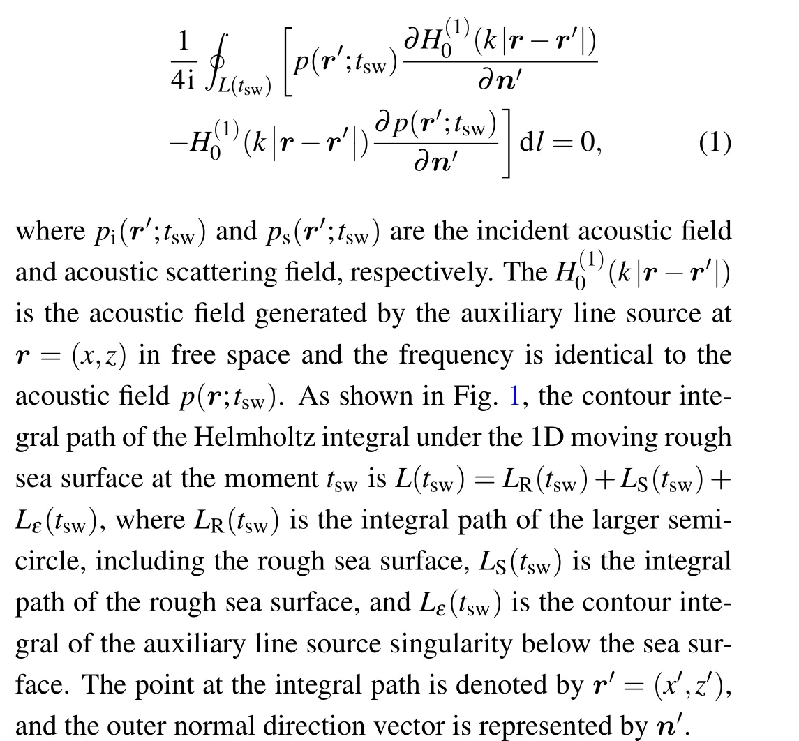
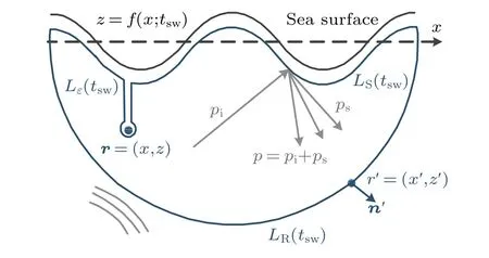
Fig.1.Helmholtz contour integral path for rough sea surface.
According to the division of the integral path and definingrs=|r-r′|:
ForLε(tsw), considering that its radius tends to approach 0,this path is almost a contour path around the singularity and the outer normal direction of this overall path is the inner normal direction of the small-radius contour path, that is,∂/∂n′=-∂/∂rs.Considering the polar coordinate system and asymptotic expansion of the Hankel function,the last term on the left-hand in Eq.(2)can be written as
ForLR(tsw), when its radius tends to approach infinity, according to the Helmholtz integral formula in a homogeneous medium and radiation condition of the scattered field,we obtain
Therefore,the total acoustic pressure field can be obtained as follows:
Due to the difference in acoustic impedance between air and water,the transmitted acoustic intensity in air is much smaller than the acoustic field in water.Even in the case of normal incidence, the transmitted acoustic intensity is much weaker than that in water.Meanwhile, considering that the fluctuation of the sea surface is relatively smooth on a low-frequency acoustic wavelength scale, the acoustic boundary condition can be viewed as absolute soft boundary for sea surface in the case of low-frequency acoustic wave incidence.As a result,we can obtain the low-frequency acoustic pressure field on the rough sea surface:p(r′;tsw)||r′=LS(tsw)≡0, and equation (5)can be written as
The first term and the second term on the right side of Eq.(6)are the contributions of the incident acoustic wave and the scattered acoustic wave by the rough interface to the total acoustic field,respectively.
For the moving rough sea surfacez=f(x;tsw), i.e.,r=(x,f(x;tsw)), considering the pressure-release boundary condition, the integral equation on the moving rough sea surface can be written as
Based on the incident acoustic wave field and derivative of the rough sea surface along the discretizing rough sea surface,∂p(r′;tsw)/∂n′will be calculated in all discretized areas, and this matrix equation obtained by discrete processing can be written as
Considering the singularity of the Hankel function,am(tsw),Amn(tsw),andbn(tsw)are represented as follows:[6]
whereeis a natural constant,am(tsw) is the incident acoustic field,Amnis theN-th-order symmetric matrix of the zeroorder Hankel function,rm(tsw)=xmˆx+f(xm;tsw)ˆz,xm=(m-1/2)Δx-L/2,Δx=L/N,andLis the calculated length of the sea surface.
According to Eq.(6) and the far-field approximation of the Hankel function, the acoustic scattering field atr=(x,z)can be expressed as
2.2.Acoustic field model based on parabolic equation
For actual ocean sound waveguides with rough sea surface, the calculation method based on the integral equation has limited the capability in quantifying the acoustic scattering field.Considering the ocean waveguide environment characteristics,the low-frequency band,and multistatic acoustic detection, an acoustic forward scattering field model is derived from the parabolic equation for the quantitative approach.Like the integral equation, we assume that the sea surface motion related to gravity waves is so slow that the wavy surface appears frozen relative to the motion caused by sound.[18]Consequently,the ocean waveguide with a moving rough sea surface can be viewed as a series of relatively stationary range-dependent waveguides.
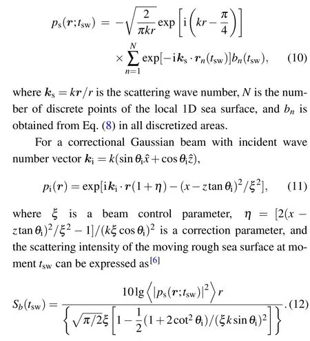
At the range-dependent waveguide in each stationary momenttsw,the harmonic acoustic fieldp(r,z;tsw)is generated by continuous source with a time factor exp(-iω0t)and is governed by the Hemholtz equation:
wherek1,2=ω0/cis the acoustic wave number,andω0is the angular frequency of the acoustic wave.Based on Fourier transform theory and the acoustic fieldp(r,z;tsw) in the series oftsw, the modulated acoustic field frequency spectrum¯p(r,z;ω)with acoustic frequencyωcan be written as
The acoustic fieldp(r,z;tsw) at the momenttswis shown in Fig.2,and based on the step approximation and energy conservation,the parabolic equation satisfied by harmonic the acoustic field can be obtained as follows:
wherek0=ω0/c0is a reference sound number,withc0being a reference sound velocity.
According to the high-order Pad´e rational approximation and taking the horizontal recursion step size as Δr,we obtain
According to the spatial variation scale of the sea surface and seabed and wavelength characteristics of the lowfrequency sound field, the operator can be solved by the Galerkin nonuniform discretion of a limitedzspace; the nonuniform discrete division is shown in Fig.2.The area near the sea surface is divided into small steps to fully characterize the influence of the rough sea surface.Meanwhile, the area below the sea surface after several wavelengths is divided into a sparse discrete area with a large step size to achieve rapid calculation.A transition discrete area exists between these two areas to avoid the large difference in step length, which may cause numerical instability.At the same time,a perfectly matched layer with functiong(z)is adopted to avoid affecting the reflection field at the boundary of the seabed truncation,and the calculation amount in the vertical direction is effectively reduced.The operator function of each vertical discrete pointzj(j=Nzs(r),...,Nz)can then be expressed as
3.High-order scattering mechanism of moving rough sea surface based on Bragg theory
3.1.Scattering intensity of sinusoidal rough sea surface
Regardless of swell, wind, and mixed waves, the rough sea surface can decompose into harmonics.Therefore,to characterize the effect of an actual rough sea surface, a rough sea surface composed of a single harmonic wave is analyzed.Considering the gravity force as the restoring force in rough sea surface,the following dispersion relation is satisfied by the sea surface wave numberksw=2π/λswand the sea surface wave angular frequencyωsw=2π fsw:[21]
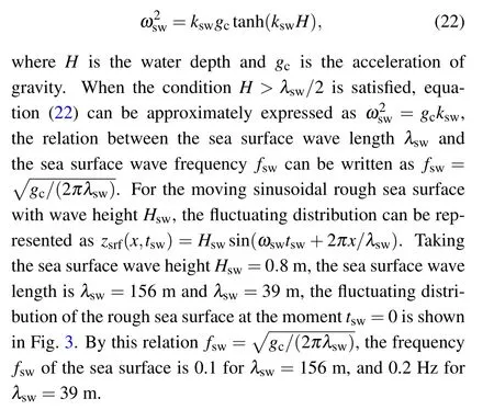
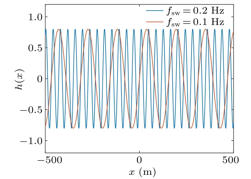
Fig.3.Sinusoidal rough sea surface.
When the modified Gaussian beams with different sound frequencies are incident at 30°, the comb-shaped distribution of the acoustic scattering intensity at a depth of 1 m is shown in Fig.4.In addition to the mirror reflection, multiple strong acoustic scattering sidelobes are noted along the discrete grazing angle.The strong scattering sidelobe distribution is consistent with the Fourier series result of the sea surface period under a Rayleigh assumption.[16]With the increase of acoustic wave frequency, the strong scattering sidelobe becomes narrower and the number of sidelobe increases.Furthermore,according to the dispersion of the gravity wave, the decrease in the frequency of the sea surface causes the sea surface wavelength to grow considerably.For instance,when the rough sea surface frequency decreases from 0.2 Hz to 0.1 Hz,the sea surface wavelength increases from 39 m to 156 m.This change in the sea surface wavelength considerably increases the number of strong scattering side lobes.
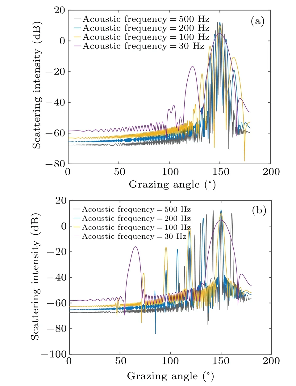
Fig.4.Acoustic scattering intensities of sinusoidal rough sea surface at(a)sea surface frequency=0.1 Hz(a)and 0.2 Hz(b).
3.2.High-order Bragg scattering and frequency shift under sinusoidal rough sea surface
Based on the first-order Bragg scattering theory and higher-order perturbation theory, Lynch and D’Spain discussed the first-order strong scattering sidelobe.[13]The firstorder Bragg scattering theory explains the generation of the first-order strong scattering sidelobe, the higher-order perturbation theory predicts its strength, consistent with the measurements.However,the higher-order perturbation theory cannot accurately predict higher-order scattering sidelobes.Thus,we use the high-order Bragg scattering theory to analyze the high-order strong acoustic scattering process.
The acoustic wavelength isλ,the incident acoustic beam isθi,the scattering acoustic beam isθs,and the grazing angle is taken to be positive in the counterclockwise direction.The periodic rough sea surface can be regarded as a“grating”with equal interval lengths, which is the wavelength of the rough sea surfaceλsw(Fig.5).The difference in path of the forward scattering field between adjacent acoustic beams is
When acoustic waves numberk=2π/λand path differenceLsatisfykL=±2nπ, the adjacent acoustic beams will form a constructive interference.Therefore, in addition to the mirror reflection, there are strong acoustic scattering side lobes in constructive interference directions.These directions of the strong acoustic scattering sidelobes are described by
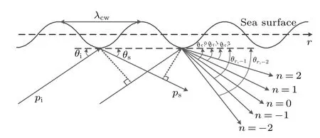
Fig.5.The high-order Bragg scattering under a rough sea surface.
Because|cosθs|≤1 and|cosθi|≤1 in Eq.(24), the order of the strong scattering sidelobe is affected by the incident acoustic wavelength and the rough sea surface wavelength.As the acoustic wave wavelength increases,the number of strong acoustic scattering side lobes will decrease.Meanwhile, as the sea surface wavelength increases,the number of the strong scattering side lobes will increase.These results are consistent with the simulated scattering intensity based on the integral equation.
When the rough sea surface moves horizontally at a velocityvsw=ωswλsw/(2π),the frequency of the coherent angular acoustic scattering field is obtained from the Doppler frequency shift as follows:
wherecis the acoustic speed in water.When the rough sea surface velocity direction is consistent with the horizontalrdirection, +vswis used; otherwise,-vswis used.By defining the rough sea surface velocity sign operator [vsw]=±vsw/|vsw|and according to Eqs.(24)and(25),we obtain
which shows that the strong scattering sidelobe Doppler frequency shift caused by the time-evolving sea surface is only related to the sidelobe ordernand frequency of the moving rough sea surfaceωsw.The frequency of the incident acoustic wave is unrelated to the sidelobe Doppler frequency shift.Even if the frequency of incident acoustic is very low,the scattering effect of the moving sea surface can produce an obvious frequency shift, which is different from the conventional Doppler frequency shift of moving sound source and receiver.
The periodic rough sea surface is represented aszsrf(r,tsw)=Hswsin(ωswtsw+2πr/λsw), and the sea surface movement direction is opposite to the horizontal direction(i.e.rdirection).The rough sea surface amplitude is 0.8 m,and the sea surface frequency is 0.2 Hz.Gravity is considered as the sea surface restoring force, that is,ω2sw=gcksw.The ocean sound velocity is 1500 m/s, the density is 1.0 g/cm3, and the sea water depth is 1800 m.The acoustic source frequency is 500 Hz, whereby the acoustic beam is uniformly distributed in 600 m-1000 m,and the grazing angle of the main acoustic wave beam is 30°.Based on this uniformly distributed acoustic source with wave beam towards sea surface, the effect of seabed is not considered to avoid further complications in the high-order Bragg scattering field,though this effect can be calculated by the parabolic equation.The acoustic field loss distributions under rough and smooth sea surfaces are shown in Fig.6.
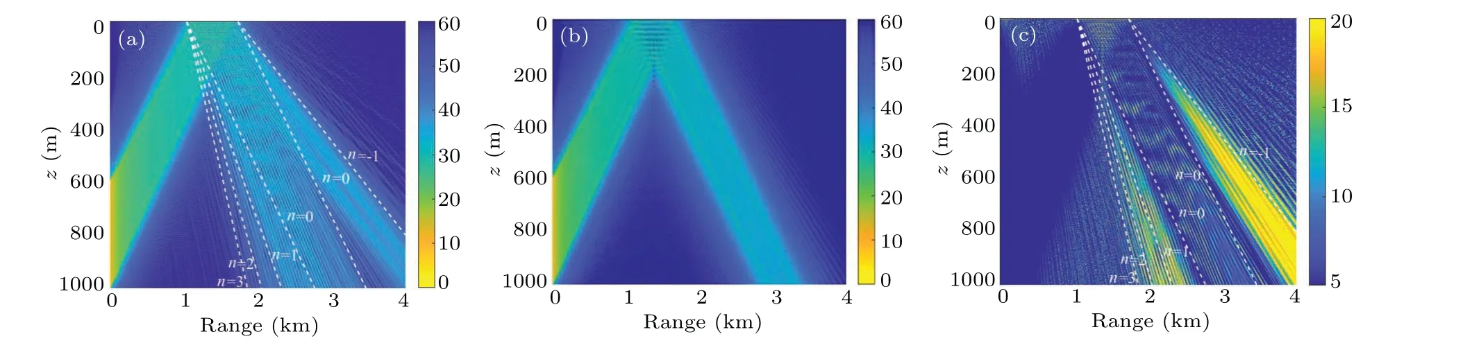
Fig.6.Acoustic field loss distribution under high-order Bragg acoustic scattering in(a)rough sea surface case, (b)smooth sea surface case,and for(c)differences in acoustic field loss distribution.
It can be seen that the constructive interference can cause the periodic rough sea surface to produce a multiorder obvious scattering field distribution as marked by the white dotted lines in Fig.6.The Bragg scattering angle distribution is consistent with the strong scattering sidelobe angle distribution in Fig.4(b).According to Eq.(24),multiorder Bragg scattering will appear in the positivendirection,whereas only one order Bragg scattering will appear in the negativendirection.However,in addition to these Bragg scattering fields at an incident angle of 30°, the other interference pattern represents higherorder Bragg scattering that can be observed outsiden=-1 andn=3,which can be explained by the acoustic field computation.Although the incident acoustic beam limits the grazing angle to 30°, additional grazing angle is considered the inappropriate local line source along the vertical direction in the parabolic equation.As shown in Fig.6, there are trajectories outside the main incident acoustic beam,which generate additional high-order Bragg scattering field after being incident on the rough sea surface.
When the underwater acoustic wave with a frequency of 500 Hz is incident on the rough sea surface,the periodic rough sea surface frequency represented aszsrf(r,t)=Hswsin(ωswt+2πr/λsw) is 0.2 Hz.The forward acoustic fields can be calculated at different time and sea surface states.Based on the fast Fourier transform of forward acoustic fields,the frequency shifts of the forward acoustic field at different receiving positions (r,zr) can be obtained, and the results are shown in Fig.7.After deducting,xaxis indicates the frequency shift from acoustic frequency.
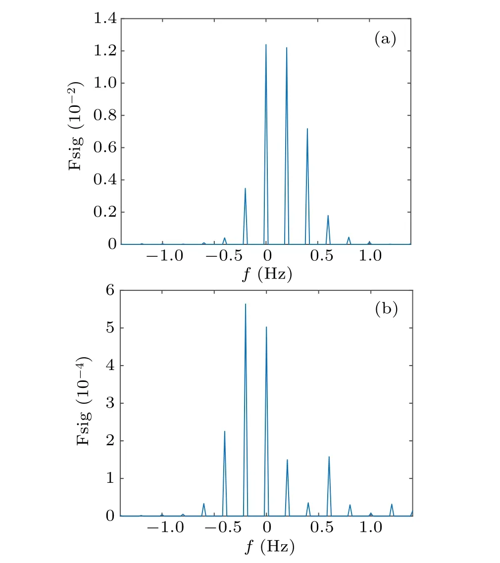
Fig.7.Acoustic frequency shift distribution under high-order Bragg scattering at receiver locations of (a) (2 km, 400 m) and (b) (4 km,500 m).
As shown in Fig.7,besides the 0 Hz frequency shift corresponding to mirror reflection, periodic sea surface motion produces an obvious frequency shift, which is a multiple of the moving rough sea surface frequency.It should be noted that the frequency shifts and scattering intensities are different at different receiver positions.For the receiver location(2 km,400 m), there is a strong first-order Bragg scattering control area,corresponding to the source at a depth of 600 m.Therefore,it has a strong positive frequency shift of 0.2 Hz with the acoustic wave amplitude similar to the mirror reflection wave amplitude.For the receiver location (4 km, 500 m), there is a strong first-order Bragg scattering control area corresponding to the source at a depth of 1000 m.Therefore, a strong positive frequency shift of 0.2 Hz is created, and its acoustic wave amplitude is higher than that of the mirror reflection wave without the frequency shift.That is,the peak frequency of the received acoustic wave signal may deviate from the actual incident acoustic frequency.At the same time,the calculated frequency shift order is higher than frequency shift order of the Bragg scattering,as shown by the white dotted lines in Fig.6, which further verifies the high-order Bragg scattering caused by the inappropriate local line source in the acoustic beam simulation.
4.Frequency shift of low-frequency acoustic field under wind and swell waves
4.1.Simulation of a moving rough sea surface under wind and swell waves
The actual sea surface is considerably more complicated than the assumed sinusoidal periodic sea surface.In particular, the sea surface waves are composed of wind wave and swell wave, which appear out of different causes.As such,they have different characteristic parameters,such as spectral peak frequency,wave height,and spectral moment,which are standards for their separation.
Fig.8.Spectral densities of different wave spectra under different wind speeds: (a) PM spectrum and (b) JONSWAP spectrum (wind distance of 7 km).
Considering the wind speed at the sea surface,wind area length, and sea depth, various wave spectra have been developed to describe rough sea surface, such as the Pierson-Moskowitz (PM) and Joint North Sea Wave Project (JONSWAP) spectra.Figure 8 illustrates the power spectral density under different wind speed parameters calculated from the PM spectrum and JONSWAP spectrum, which represent steady sea surface and unsteady sea surface,respectively.
The simulation results show that the fully grown sea surface waves represented by the PM spectrum have a low spectral peak frequency distribution and a steep spectral density distribution.The insufficiently grown sea surface waves represented by the JONSWAP spectrum have a flatter power spectral density distribution and a higher spectral peak frequency distribution.Swell waves are low-frequency components propagated by the fully grown sea surface waves at a distance,with their high-frequency sea surface components attenuated rapidly.Conversely, wind waves are affected by the local wind.Therefore, the sea surface under swell waves is smooth and can be depicted as a sine wave, whereas the sea surface under wind waves is randomly rough and has a higher sea surface high-frequency distribution and can be simulated by the Monte-Carlo and wave spectrum methods.According to the Monte-Carlo method, a sea surface with wind waves comprises multiple harmonic components, which have their own random intensity and phase.For a single-dimensional rough sea surface with lengthLand discrete numberN, the moving sea surface direction is opposite to the horizontalrdirection and the random rough sea surface height at discrete sampling pointsrnat timetcan be expressed as
whereS(kswj) is the power spectral density of the rough surface,ωswjis the angular frequency of the sea surface corresponding to wave numberkswj,andN(0,1)is a standard normal distribution random number.The harmonic spectrum of the negative wavenumberkswj=2π j/L(j=-N/2,...,-1)is the complex conjugate of the positive wavenumber harmonic spectrum.Based on this method,the sea surface of the wind waves represented by the PM spectrum is simulated,and the results are shown in Fig.9.The sea surface simulation of the swell wave is also depicted as a sine wave with a spectral peak frequency of 0.1 Hz,which is identical to that of the PM spectrum wind wave.
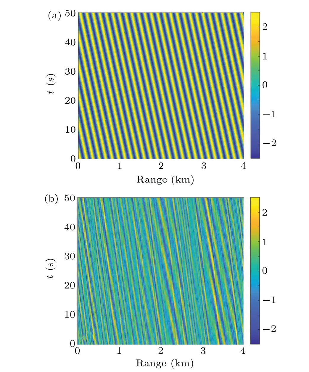
Fig.9.Sea surface simulations with the swell and fully grown wind waves: (a) sea surface with swell wave and (b) sea surface with wind waves(PM spectrum).
It can be seen from Fig.9 that both swell wave with a spectral peak frequency of 0.1 Hz and fully grown wind wave have identical amplitude peaks of approximately 2.5 m.The oblique stripes reflect the sea surface wave propagation characteristics.Compared with the swell waves simulated as sine waves,the wind waves have significant random and highfrequency components,which are reduced periodic regularity.
4.2.High-order Bragg scattering and frequency shift of rough sea surface with wind and swell waves
For the sea surface with swell waves and fully grown wind waves, when an acoustic wave with a frequency of 200 Hz is incident,the acoustic scattering field distribution and frequency shift can be calculated by the same method as that in Figs.6 and 7.Besides the acoustic wave frequency,other parameters are similar to those in the simulation in Fig.6.The results of the acoustic scattering field distribution and frequency shift at(3 km,250 m)with swell waves and fully grown wind waves are shown in Figs.10 and 11, respectively.The simulations illustrate that the sea surface with swell waves and fully grown wind waves can cause an obvious acoustic scattering field and frequency shift for low frequency acoustic wave.However, for the sea surfaces with different wave types, the acoustic scattering field and frequency shift are obviously different.
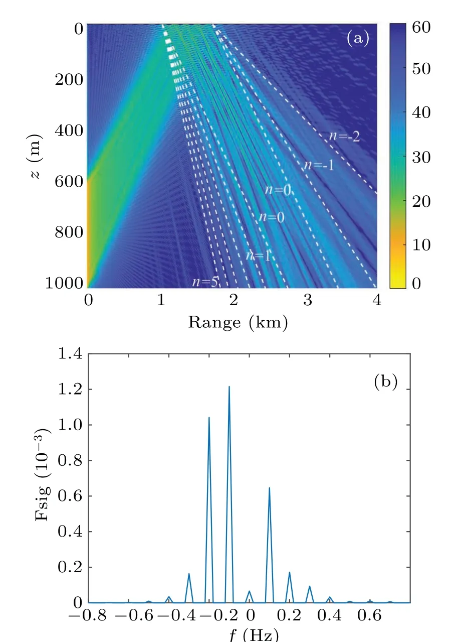
Fig.10.Higher-order Bragg scattering of rough sea surface with swell waves: (a) acoustic scattering field loss distribution and (b) frequency shift at(3 km,250 m).
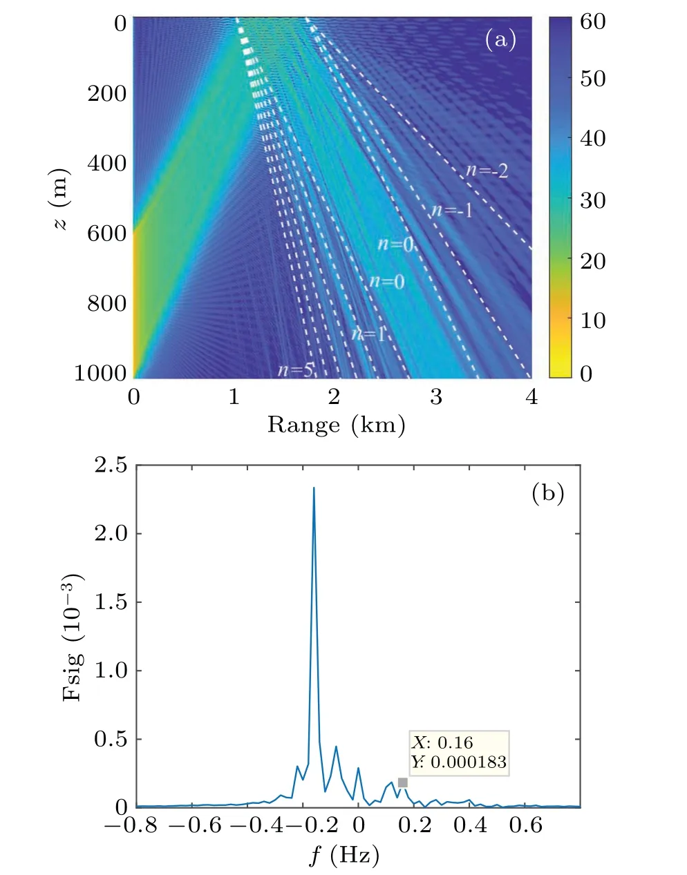
Fig.11.Higher-order Bragg scattering of rough sea surface with fully grown wind waves: (a)acoustic scattering field loss distribution and(b)frequency shift at(3 km,250 m).
As shown in Fig.10, the Bragg acoustic scattering field under the periodically time-evolving sea surface is not related to the incident acoustic wave frequency.It multiplies with the sea surface periodical frequency.Therefore, multiple frequency shifts of 0.1 Hz are noted.The sea surface with a large wave height produces a more obvious scattering field and frequency shift.At (3 km, 250 m), the Bragg scattering frequency shifts of ordersn=-1 andn=-2 are consistent with the scattering field distribution in Fig.10(a).Moreover,the acoustic intensity after the frequency shift is considerably higher than that of the mirror reflection without the frequency shift.Compared with the moving sea surface with swell waves characterized by a single frequency,the rough sea surface with fully grown wind waves has a more complex scattering field as shown in Fig.11.For the sea surface with fully grown wind waves, the interference of the sea surface wave with multiple fluctuating frequencies changes the strength of the acoustic scattering field.In addition to the strong Bragg acoustic scattering,a frequency shift is noted from-0.4 Hz to 0.4 Hz,and the strongest frequency shift is slightly different from the multiple with the wind wave spectral peak frequency of 0.1 Hz,as shown in Fig.8(a).For this difference in the strongest frequency shift, it can be explained from the wavelength selection of Bragg scattering and the interference between acoustic scattering beams.During the Bragg scattering of rough sea surface, only a narrow part of the sea spectrum gives rise to strong scattering,while the remaining part of the spectrum produces second order effects.[18]Meanwhile, corresponding to each spatial distributed acoustic source in these simulations,the incident acoustic beam is modulated by the rough sea surface,and the strong acoustic scattering field is produced along the respective Bragg scattering direction.The strong acoustic scattering fields from different acoustic sources will be interfere with each other, creating an additional pattern where the scattering waves with different frequency shifts either cancel out or reinforce each other.
For the wind wave at an average wind speed of 10 m/s at 10 m above the sea surface and a wind distance of 7 km,the rough sea surface with insufficiently grown wind waves is simulated by the JONSWAP spectrum.Figure 12 shows the sea surface under unsteady wind waves and mixed waves.The mixed wave is the superposition of the simulated insufficiently grown wind wave and swell wave,the spectral peak frequency of insufficiently grown wind wave and swell wave are 0.4 Hz and 0.1 Hz, respectively.The wave height of the rough sea surface with wind waves (Fig.12(a)) is smaller than that under swell waves and fully grown wind waves.Because of the randomness of the wind waves,the wave height of the sea surface under mixed waves (Fig.12(b)) is also random.With the acoustic wave with acoustic beam parameters,as shown in Fig.10,the acoustic scattering field under the sea surface with insufficiently grown wind and mixed waves can be calculated,and the results are shown in Figs.13 and 14,respectively.
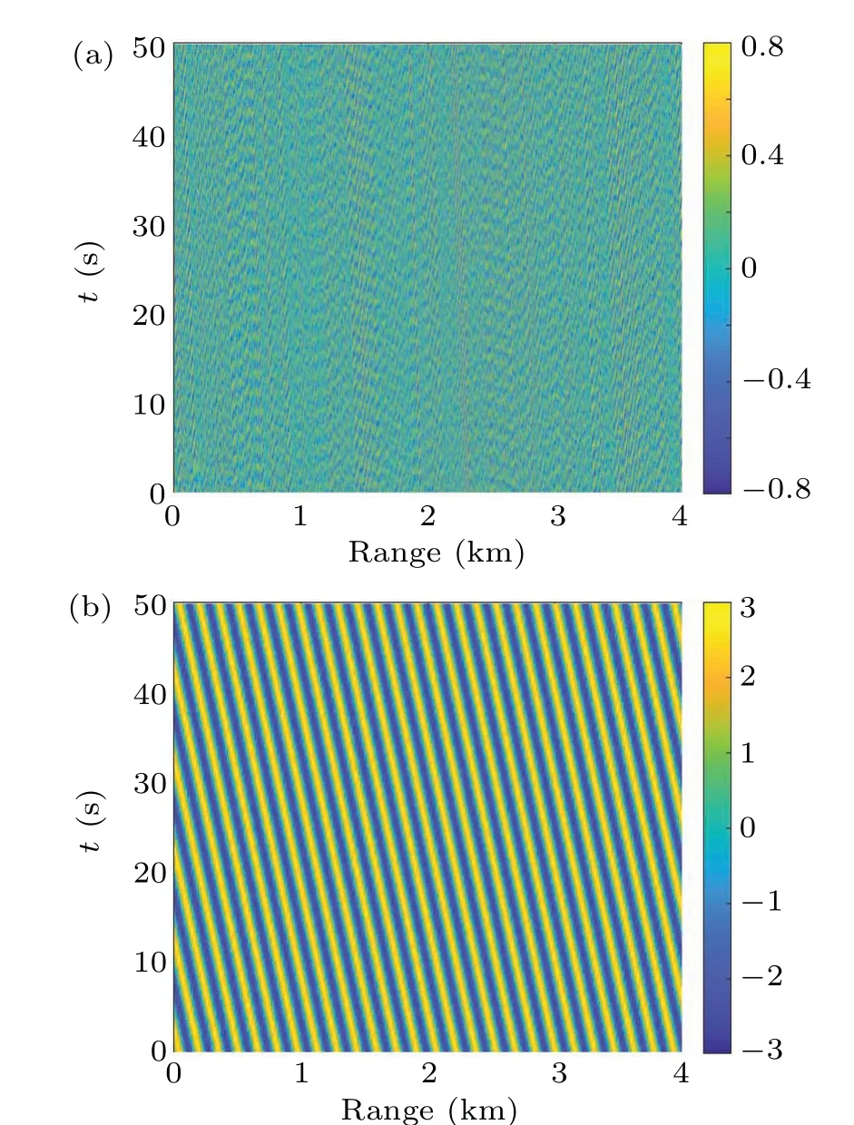
Fig.12.Sea surface simulations with (a) insufficiently grown wind waves(JONSWAP spectrum)and(b)mixed waves.
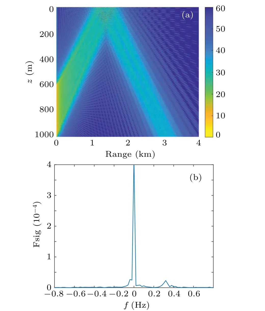
Fig.13.Higher-order Bragg scattering of a rough sea surface with insufficiently grown wind waves: (a)acoustic scattering field loss distribution and(b)frequency shift at(3 km,250 m).
Figure 13 shows that the reflection acoustic field accounts for the absolute main component when the sea surface is affected by insufficiently grown wind waves,and the scattering acoustic field is weaker than that of the other rough sea surface wave cases.The absence of a frequency shift in Fig.13(b)further verifies this reflection acting as the main component of the acoustic field.In other simulation cases, the Bragg scattering field at the receiving position of (3 km, 250 m) has higher acoustic intensity,whereas the frequency shift with insufficiently grown wind waves is negligible in a weak case at 0.32 Hz only.The weak frequency shift results from the lower height of the unsteady rough sea surface.In particular, the wave spectrum of the unsteady sea surface has a wider frequency band that results in the interference of more harmonic components of the frequencies, reducing the scattering intensity and frequency shift.Meanwhile, the frequency shift for the sea surface with unsteady wind waves is not proportional to the wind spectrum peak frequency as shown in Fig.8(b),which is similar to the results shown in Fig.11.
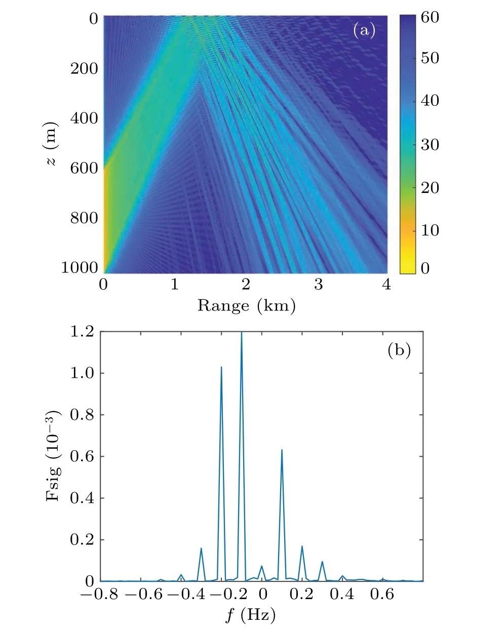
Fig.14.Higher-order Bragg scattering of rough sea surface with mixed waves: (a) acoustic scattering field loss distribution and (b) frequency shift at(3 km,250 m).
Comparing with the single insufficiently grown wind wave, the acoustic scattering field and frequency shift are very obvious in the case of the sea surface with mixed waves(Fig.14).Further,the acoustic scattering field distribution and frequency shift are almost consistent with those observed in the case of the sea surface with swell waves(Fig.10).In particular, there are multi-order high-intensity Bragg scatterings and a proportional frequency shift of 0.1 Hz.The highest order obvious frequency shift is 0.4 Hz.The frequency shift also preliminarily reflects the influence of the insufficiently grown wind waves,and the comb-shaped multi-order frequency shift is superimposed on the small frequency-shift fluctuations in the case of the sea surface with insufficiently grown wind waves.
5.Conclusions
Based on the sea surface acoustic scattering obtained by the integral equation and forward acoustic field calculation method through using the parabolic equation, the acoustic scattering and frequency shift caused by a moving rough sea surface are calculated and analyzed.The simulation results show that the acoustic scattering field is enhanced at a series of discrete scatter angles stratified by constructive interference,which produces the comb-like high-order Bragg scattering and frequency shifts.The acoustic scattering field has an obvious strong scattering sidelobe along multiple Bragg scattering angle, and its scattering intensity is slightly lower than that of the mirror reflection field.The order of the Bragg acoustic scattering field is directly proportional to the frequency of incident acoustic wave, but inversely proportional to the frequency of sea surface fluctuations.Even if the frequency of incident acoustic is low, Bragg scattering is generated under an actual periodic moving sea surface.The acoustic field along each Bragg scattering angle direction has an obvious frequency shift caused by the periodic sea surface, which is considerably different from the conventional acoustic Doppler frequency shift.In particular, this is attributed to the Bragg scattering order and moving sea surface frequency, but is unrelated to the incident acoustic wave frequency.Considerable frequency shift is noted with low or ultralow incident acoustic frequencies.Therefore, the frequency shift is non-negligible for underwater low-frequency and extremely low-frequency acoustic measurement.
Meanwhile, the acoustic scattering field and frequency shift distribution for a rough sea surface with typical swell,wind, and mixed waves are analyzed.There are obvious differences in the Bragg acoustic scattering field and frequency shift between the sea surface with swell waves and the sea surface with wind waves.Based on the high-order Bragg acoustic scattering field and acoustic frequency shift,different types of sea wave spectrum peak frequencies and other characteristics are obtained.Compared with the sea surface with fully and insufficiently grown wind waves, the sea surface with swell waves is dominated by a single harmonic component,forming a considerable multi-order Bragg acoustic scattering field and comb-like frequency shift that is a multiple of the wave frequency.The sea surface with fully grown wind waves exhibits multi-order Bragg acoustic scattering field and frequency shift.However, the comb-like frequency shift is less obvious than that under the sea surface with swell waves.The strongest frequency shift is not proportional to the peak frequency of the wind wave spectrum.The insufficiently grown wind wave spectrum has a wider frequency distribution and higher peak frequency, while the Bragg acoustic scattering field and frequency shift distribution are extremely weaker.Under low wind speed and short wind distance, an inconspicuous frequency shift is noted on the acoustic wave, which was not proportional to the peak frequency of the wind wave spectrum either.When the insufficiently grown wind waves and swell waves are mutually superposed to form mixed waves,the Bragg acoustic scattering field and frequency shift are mainly due to the effect of the swell sea surface under the sea surface with mixed waves.
Acknowledgements
Project supported by the IACAS Young Elite Researcher Project(Grant No.QNYC201703),the Rising Star Foundation of Integrated Research Center for Islands and Reefs Sciences,CAS(Grant No.ZDRW-XH-2021-2-04),and the Key Laboratory Foundation of Acoustic Science and Technology (Grant No.2021-JCJQ-LB-066-08).
猜你喜欢
微型计算机·Geek(2020年5期)2020-06-15
宁夏画报(2019年5期)2019-09-19
中学生数理化·八年级物理人教版(2019年6期)2019-06-25
故事会(2017年23期)2017-12-08
优雅(2017年11期)2017-11-11
Coco薇(2017年9期)2017-09-07
宁夏画报(2016年9期)2016-11-21
中学生数理化·八年级物理人教版(2016年6期)2016-08-27
Coco薇(2016年2期)2016-03-22
宁夏画报(2016年1期)2016-02-23

- Chinese Physics B的其它文章
- Does the Hartman effect exist in triangular barriers
- Quantum geometric tensor and the topological characterization of the extended Su–Schrieffer–Heeger model
- A lightweight symmetric image encryption cryptosystem in wavelet domain based on an improved sine map
- Effects of drive imbalance on the particle emission from a Bose–Einstein condensate in a one-dimensional lattice
- A new quantum key distribution resource allocation and routing optimization scheme
- Coexistence behavior of asymmetric attractors in hyperbolic-type memristive Hopfield neural network and its application in image encryption