
Dynamic Modeling and Optimization Design on Underwater Gliders
2010-12-13 02:56ZHANGHongweiWANGYanhuiCHENChaoyingZHUGuangwen
船舶力学 2010年3期
ZHANG Hong-wei,WANG Yan-hui,CHEN Chao-ying,ZHU Guang-wen
(1 Tianjin University,Tianjin 300072,China;2 National Ocean Technology Center,Tianjin 300111,China)
1 Introduction
In recent years,underwater gliders have received increased attention from both academia and industry.The concept for conventional underwater gliders is derived from autonomous underwater floats which were first proposed by Henry Stommel in 1989[1].The first prototype of the underwater glider was designed by Webb Research Corp.in the U.S.A.in 1995[2].Since their introduction,underwater gliders have been used extensively for oceanographic sensing and data collection.They have special buoyancy devices that make them attractive for these applications.The buoyancy devices alternately reduce and expand the volume of water displaced by the glider,thereby controlling the dive and climb of the glider through the water.The resulting motion of the glider is a saw-toothed pattern.By controlling these devices,the glider can be made to follow programmed trajectories.Additional advantages of underwater gliders include their low cost,low power consumption,autonomy,and capability for long-range sorties.
The United States[2-4],Japan[5],France[6-7],New Zealand[8],Canada[9]and Australia[10]all carried out the study of underwater gliders.Nowadays there are three typical kinds of underwater gliders:Slocum,Spray and Seaglider.They are all developed by the United States.China began underwater gliders’researches at the beginning of this century.Tianjin University,National Ocean Technology Center,Shenyang Institute of Automation,Zhejing University,China Ship Scientific Research Center and Northwest Polytechnical University are all doing the research of underwater gliders and some theories and technologies are published[11-15].
Tianjin University,cooperating with National Ocean Technology Center,developed an experimental prototype of underwater glider propelled by temperature difference energy in 2005.The underwater glider contains pressure hull,pose control setups,fixed wings,controller and communication module,buoyancy changing module by temperature difference energy and sensor module.The underwater glider is 52kg in air and has a buoyancy adjusting capability of 350ml.The cruise speed is 0.5 kns.Working depth is up to 100m.The glider makes the buoyancy changing be reality using a special hydraulic system which can absorb temperature difference energy.
2 Modeling of gliders
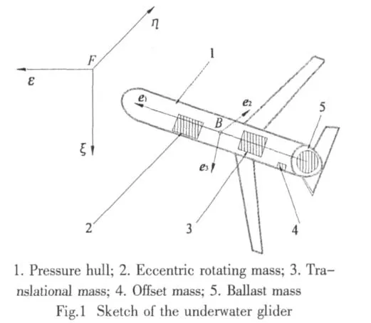
Fig.1 is the sketch of an underwater glider.It shows the main factors of the glider,consisting of a pressure hull,two fixed external wings and tails and moving internal masses.The pressure hull is considered as the rigid base body that can translate and/or rotate in the fluid field.
2.1 Kinematics
The inertial frame and the coordinate frame attached to the glider’s body are shown in Fig.1.The main external forces and moments acting on the glider are the hydrodynamic forces and moments caused by the glider’s motion in the water.Buoyancy and gravitational forces are two other external forces that act on the glider.
Internal actuators are used to control its attitude.An underwater glider is in its neutral state when buoyancy and gravitational forces balance.It has two bladders.One is an internal reservoir that is sealed in the pressure hull and the other is an external bladder that is flushed.When the external bladder deflates,the glider sinks because the gravity of the underwater glider remains constant while the buoyancy decreases.Conversely,the glider ascends when the external bladder inflates.In this paper,the ballast mass is used to represent this buoyant system.As a result of the hydrodynamic forces acting on the fixed horizontal wings,this alternating movement is converted into glide.When it works,the glider will have a saw-toothed trajectory in the vertical plane.The translational mass,which moves along the e1axis,controls the glider’s pitch.The eccentric turn along the e1axis of the rotating mass gives the glider a rolling motion which causes the glider turn to left or right.The definition of the variables is shown in Tab.1.
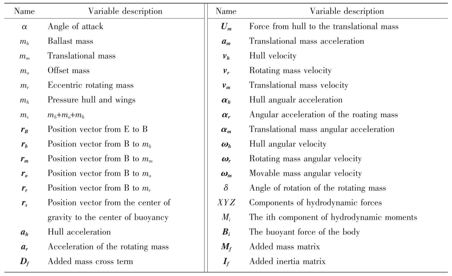
Tab.1 Definition of variables
The pose of the glider is defined as follows:The B-e1e2e3coordinate frame is first superposed with the E-εηξ coordinate frame.Then the glider is made to rotate about the e1,e2,and e3axes with the angles φ,θ,and ψ respectively.We select ε,η,ξ,φ,θ,ψ,δ,and rm1as generalized coordinates and define S01as the rotation matrix that describes the transformation from body coordinates to inertial coordinates.
Thus the angular velocity of the glider’s hull can be expressed in inertial coordinates as:

The positions of the rigid bodies are expressed in inertial coordinates.These position vectors are differentiated with respect to time in order to obtain velocities.The acceleration of the bodies is found by differentiating the velocity with respect to time.
2.2 Dynamics
The Gibbs function of the glider system is expressed as follows:

when Gs,Gr,Gmand Gfrepresent the Gibbs functions of the bodies respectively.The elements of the matrix are defined as follows:

while all the other values of gij=0i,j=1…7.
Using Appel equations,the following can be obtained:

Because the glider is a holonomic dynamic system,the generalized force is:
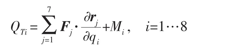
where Fjis the force on the jth body shown in Fig.2,and Miis the moment according to the ith generalized coordinate.
2.3 Simplification of the dynamic model
The running characteristics of underwater gliders in the vertical plane are important to the design and analysis of the glider.When the motion of the glider is restricted to the vertical plane,the dynamic equations of the glider can be simplified as follows:the pressure hull of the glider is considered as uniform,so that the hull mass is distributed and the center of buoyancy is the same to the center of gravity;the offset mass is negligible;the rotating mass is resting when the glider is restricted to move in vertical plane.From the above simplifications,it can be observed that φ=ψ=η=rm2=rm3=rr2=δ=0.Thus,

Because of the symmetrical shape of the underwater glider,the added mass can be expressed as follows[16]:

Substituting these parameters into equations(2)and(3)gives the dynamic equations of the glider in vertical plane

where
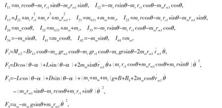
others Iij=0i,j=1…4
2.4 Hydrodynamic forces and moments
In this section,the hydrodynamic forces and moments in E-εξ plane are derived.
The aerodynamic drag(D),lift(L)and moment(M)of the underwater glider in the vertical plane can be calculated using the following equations[17]:

In equations(5),(6)and(7),parameters KD0,KD,KL0,KL,KM0,KM,Kθ1,Kθ2are aerodynamic coefficients and can be identified by tank experiments or CFD analysis.The software,FLUENT,is used to perform the CFD analysis of the underwater glider.The use of virtual experi-ments saves the cost of physical experiments and is convenient for varying the parameters of the glider.
The fixed horizontal wings are symmetrical slats which are suitable for the low velocity of the glider.The position of the wings relative to the hull is important to the gliding capability.In order to obtain a better design,three virtual designs with varying wing positions are presented.The three designs are shown in Fig.2.
The following steps are used to calculate the aerodynamic coefficients for each of the design models.Firstly,with the velocity fixed at 0.3m/s and the angular velocity set to zero,the drag,lift and moment are calculated for angles of attack ranging from-5°to 5°.The step size in the angles is 1°.Thus we get 11 drags,lifts and moments at the different angles of attack respectively.Then,using the Least-Squares Method and equations(5),(6),and(7),all the parameters,with the exception of Kθ1and Kθ2can be identified.The moving nets method,which is a part of the FLUENT software,can be used to identify Kθ1and Kθ2by putting KM0and KMin equation(7)and using varying values for the angular velocities.
Tab.2 shows the values of the aerodynamic coefficients for the three different designs.

Tab.2 Parameter values for the three gliders
According to Ref.[17],we choose the added mass as follows:
3 Design for fixed wings’position
Oceanographic gliders are designed for long ranges and typically have very low power consumption.Additionally,oceanographic sensors are placed on gliders in order to keep gliders within the working range during glider missions.The positions of the glider’s external wings have a significant influence on the dynamic behavior of underwater gliders.This in turn influences the power consumption and sensor states.
In order to improve the horizontal velocity,the steady pitch angle of this glider is set to±38°[11],and because of the glider’s structure,the position vectors are set to rr1=0.3m,rr3=0.05m,rb1=-0.7m.When the position of the origin of the translational mass is-0.3m,the ballast mass has a buoyancy of±0.05kg.The mass of each body in the glider’s design is:mh=40kg,mm=5kg,mr=5kg.Equation(4)is then used to analyze the performances of the three gliders.
From Fig.3(c),it can be clearly observed that this glider requires only 0.039 m’s movement of the translational mass to get a desired pitch angle while the gliders shown in Fig.3(a)and(b)require 0.054m and 0.046m,respectively.Since servos are used to change the position of the movable mass and since the gliders require frequent inflections between downwards and upwards,the glider in(c)is superior to the others in terms of saving energy.It can also be observed that glider(a)has a large overshoot.The pitch angle of this glider before steady state gliding is more than 60°.Since a compass with a measuring range of±60°is used to measure the pitch angle,glider(a)is out of the range of the compass.The greater number of oscillations of glider(b)before steady state is achieved affects the measurements obtained form the sensors.As a result,glider(c)is selected for the final design.The time needed for glider(c)to attain a steady gliding state is determined to be about 50s longer than the time required for the other two gliders.These 50s can be considered as negligible because the glider operates in open waters and always runs at a low velocity.
4 Trajectory simulation and experiments
Generally,the glider travels in a saw-tooth trajectory while following programmed trajectories.Fig.4 shows the simulation results of glider’s trajectory in the E-εξ plane and also the experimental data.The cycle time of the underwater glider moving in the vertical plane is around 400s.The pitch angle of it is near 40°.According to the depth of the experiment lake,a trial depth of 32m is selected.It can be seen from Fig.4(c)that the experimental data matches well to the simulation results.

5 Conclusions
Underwater gliders have the potential to be used in an enormous number of oceanographic applications.The dynamic model of the glider developed in this paper along with the analysis conducted for the simpler model provides significant insight into the dynamic behaviors of gliders.The glider’s dynamic model presented here is general and not vehicle specific.Therefore,it can be applied to the design and optimization of gliders in general.The good correlation between the simulation and lake trial proves the validity of the proposed model.This work complements the other research that is being conducted on the design and dynamic analysis of underwater gliders.
[1]Stommel S.The Slocum mission[J].Oceanography,1989,2(1):22-25.
[2]Webb D,Simonetti P,Jones C.SLOCUM:An underwater glider propelled by environmental energy[J].IEEE Journal of Oceanic Engineering,2001,26(4):447-452.
[3]Eriksen C C,Osse T J,Light R D,et al.Seaglider:A long-range autonomous underwater vehicle for oceanographic research[J].IEEE Journal of Oceanic Engineering,2001,26(4):424-436.
[4]Sherman J,Davis R E,Owens W B,et al.The autonomous underwater glider“Spray”[J].IEEE Journal of Oceanic Engineering,2001,26(4):437-446.
[5]Tomoda Y,Kawaguchi K,Ura T,et al.Development and sea trials of a shuttle type auv ALBAC[C]//8th Int.Symposium on Unmanned Untethered Submersible Tech.Durham,NH,1993:7-13.
[6]Moitie R,Seube N.Guidance and control of an autonomous underwater glider[C]//12th Int.Symposium on Unmanned Untethered Submersible Tech.Durham,NH,2001.
[7]Ahmed-ali T,Cuillerier L,Seube N.Nonlinear identifier and observer design for an underwater glider[C]//IFAC Conf.on Maneuvering and Control of Marine Crafts.Girona,Spain,2003.
[8]Underwater deep ocean glider[EB/OL].accessed May 2008,online available at:http://www.physics.otago.ac.nz/px/research/electronics/current-research-projects/underwater-deep-ocean-glider.
[9]GSC Pacific(Sidney)-Ocean gliders in Canada[EB/OL].accessed May 2008,online available at:http://gsc.nrcan.gc.ca/org/sidney/index_e.php.
[10]Facilities-Integrated marine observing system[EB/OL].accessed May 2008,online available at:http://www.imos.org.au/facilities/ocean-gliders.html.
[11]Wang Y,Wang S,Xie C.Dynamic analysis and system design on underwater glider propelled by temperature difference energy[J].Journal of Tianjin University,2007,40(2):133-138.(in Chinese)
[12]Ma Z,Zhang H,Zhang N,et al.Study on energy and hydrodynamic performance of the underwater glider[J].Journal of Ship Mechanics,2006,10(3):64-69.
[13]Wang C,Yu J,Wu H,et al.Research on movement mechanism simulation and experiment of underwater glider[J].Ocean Engineering,2007,25(1):64-69.(in Chinese)
[14]Ge H,Xu D,Zhou Q.Dynamic modeling of a low speed underwater vehicle based on moving mass control[J].Mechanical Science and Technology,2007,26(3):327-331.(in Chinese)
[15]Kan L,Zhang Y,Fan H,et al.Buoyancy driven underwater glider motion simulation[J].Computer Engineering and Application,2007,43(18):199-201.(in Chinese)
[16]Graver J.Underwater gliders:dynamics,control and design[D].Princeton University,2005.
[17]Leonard N,Graver J.Model-based feedback control of autonomous underwater gliders[J].IEEE Journal of Oceanic Engineering,2001,26(4):633-645.

- 船舶力学的其它文章
- Generation and Propagation of Nonlinear Surface Waves in a Fully-Nonlinear Wave Flume
- Nonlinear Model Predictive Controller Design for Path Following of Underactuated Ships
- Factors Affecting the Slamming Pressure Peak Value of Trimaran Cross Structure
- Damage Detection for Offshore Platform by Wavelet Transform
- Influence of Force on the Electromagnetic Property of FSS with Apertures
- Study on Multi-objective Optimization and Multi-attribute Decision Making of Dynamic Vibration Absorber