
Influence of Force on the Electromagnetic Property of FSS with Apertures
2010-12-13 02:56ZHANGLijunWANGDeyuZHUXiZHANGLingjiang
船舶力学 2010年3期
ZHANG Li-jun,WANG De-yu,ZHU Xi,ZHANG Ling-jiang
(1 State Key Laboratory of Ocean Engineering,School of Naval Architecture,Ocean and Civil Engineering,Shanghai JiaoTong University,Shanghai 200030,China;2 Navy University of Engineering,Wuhan 430033;China;3 NAA,Beijing 100073,China)
Biography:ZHANG Li-jun(1976-),male,Ph.D.student of Shanghai Jiao Tong University,Email:zlj-hao@tom.com.
1 Introduction
Frequency selective surface(FSS)has characteristics to let electromagnetic wave at particular frequency to pass through and electromagnetic wave at the other frequencies to reflect.It can be divided into two types.One is the FSS with apertures;the other is the FSS with pitches.The FSS with apertures actually is the thin plate perforated periodically with apertures.In recent three decades,the FSS has been widely used in microwave oven,mobile telephone,satellite antenna,radar system,sensor,and so on.In these equipments,FSS is used as random,reflector and filter in reflector antenna system,polarizer and beam splitter in far-infrared region,filter in infrared sensor,an aid in the collection of sonar energy in the near-infrared and visible portion of spectrum[1-2].Now,the application of FSS is broaden to include the electromagnetic wave absorbers.This is because FSS can broaden the absorbing bandwidth of the radar absorber.In some cases,the absorbers with FSS are much thinner than those without FSS,when they have the same absorbing ability.In other cases,the absorber with FSS has a wider absorbing bandwidth than those without FSS,when they have the same thickness[2-9].
However in these applications,FSS may sometimes suffer forces[10].Simultaneously,the radar absorber structure is employed wider and wider to act as the main structure of the shell of the aircraft to endure the forces caused by the weight and fluent[11].Now the radar absorber structure is being used as the hull of the ship and the integrated mast.As a component in these stealthy structures,FSS also endures forces.When the FSS is not used as component of main structure,the FSS can be designed to be thicker to reduce the stress level in it and this kind of design method has been employed and the technology to analyze the EM property of thick FSS has been developed[10].However,the design for main structure will let the stress level to be a relative high one,in order to be economical and make good use of the strength potential of the material.This means the FSS may suffer the high static force and the high transient force caused by the ocean wave,collision and explosion.When these situations happen,whether the FSS can endure the force and maintain its EM property should be considered.In other words,when FSS is used as a part of the main structure,how about its ability to endure the force and whether will its EM property be changed by the force?To solve this problem,both the electromagnetic wave theories and mechanics theories are needed.
In latest three decades,the theories for analyzing the EM property of FSS with apertures have progressed greatly.The technology for analyzing the conducting plate perforated periodically with rectangular holes was put forward[12].Then the technologies appeared to analyze the FSSs with circular apertures[13]and other kinds of apertures such as loaded slot,multiple rectangular aperture,cross slot aperture[14-16].Simultaneously,these technologies were also used to research one layer of FSS with dielectric substrate,one layer of FSS embedded in multilayer materials[10,12-13,17].The GSM technology which was used to analyze the FSS with pitches was also used to calculate the transmission coefficient of the multilayer FSSs with apertures[18].At the same time the tunable FSS with apertures which was put on a liquid dielectric substrate was researched[19].Then,the Local Planar Technology was used to get the transmission and reflection property of curved FSS with apertures[20].
Genetic algorithm was also used into the design of FSS.But it was mostly used in the design of FSS with pitches.Firstly it was used to refine the shape of the pitches and distance between them[21-23].Then,by using the genetic algorithm,the shape of the pitches,placement pattern of pitches,the thickness and electromagnetic parameters of multilayer materials can be optimized simultaneously to meet the needs[5-6,8,24].
People also started to research the influence of the FSS on the mechanical property of main structure which was made by radar absorber structure with FSS embedded in Ref.[3].
From the progress of the technology analyzing FSS in both mechanics theory field and EM theory field,it can be concluded that the EM theories analyzing the FSS has progressed greatly and the mechanical property of the structure with FSS embedded in started to be researched,but the influence of the force on the EM property of the FSS has not been studied.In order to find out whether the FSS can maintain its EM property when it is subjected to the high-leveled force,we conducted the present research,which includes:mechanism analysis,the numerical investigation by using both mechanics FEM and EM FEM.
2 Mechanism analysis
The Mode-Matching method is wildely used to calculate the transmission and reflection property of FSS with apertures[12].The main formulas in this method are the follows.
Tangential electric fields of incident wave and reflected wave can be written as the follows by using the Floquet mode with thetime dependence omitted.

Tangential electric fields of transmitted wave can also be written as the follows in the same way.

Subscript r=1,2.They represent transverse electric(TE)mode,transverse magnetic(TM)mode.A00rrepresents the magnitude of electric field of the incident wave.Rpqr,Bpqrare the transmission and reflection coefficient of each Floquet mode,superscript→represents vector.The calculating formula ofcomprises dx,dy,α.The definitions of dx,dy,α are showed in Fig.1
According to the Maxwell equations and the formulas(1),(2),the magnetic field can also be obtained.Then the tangential electric field in the aperture is expanded in a set of functionsmeets two conditions:(1)on the boundary of the aperture,the opponent ofwhich is tangent to the edge of the aperture,is zero;(2)this set of functions is the orthonormal one.


By using the continuity condition of the tangential EM field in the aperture and Galerkin method,the equation for calculatingis gotten as below.

The Mode-Matching method shows that the geometry parameters dx,dy,relative spatial angle α are the key factors for the FSS.At the same time,the two conditions,which the functionsmust meet,will change greatly when the shape and size of the aperture alter.Thus,dx,dy,relative spatial angle α,the shape and size of the aperture play key roles in deciding the EM property of FSS,such as the resonant frequency,bandwidth.
However,when a plate with holes is subjected to force,it will deform.dx,dy,α,the shape and size of the aperture will change.Thus when the FSS is subjected to the force,its EM property will alter.
The detailed mechanism of the influence of force on the EM property of FSS is showed in Fig.2.

3 The mechanics-electromagnetics numerical co-analysis for the influence of force on EM property of FSS
There are no elastic analytic solutions for the infinite plate with multiple holes subjected to force are found,and the stress field in the plate may get into the nonlinear stage due to the stress concentration at the corner of the holes.So,the research on the deformation in the FSS can only appeal to the numerical method.
Simultaneously,in the latest three decades only the functions for the regular apertures(they are rectangular aperture,circular aperture,multiple rectangular aperture,loaded slot[13-16])are found to expand the tangential electric field in the aperture.So,in mode-matching method,it is too difficult to find a proper set of functions to expand the tangential electric field in the deformed aperture which is an irregular aperture with distorted edges.
Due to these difficulties in both mechanics and electromagnetics,the practical way is firstly to use the mechanics numerical method to calculate the shape and size of aperture,relative spatial angle and distance between the apertures in the deformed FSS;then to use the electromagnetics numerical method to calculate the frequency response of deformed FSS;finally to connect the force and the EM wave frequency-response of FSS to form a curve of EM property-force.
3.1 Geometry parameters and material property of the sample in numerical research
The geometry parameters of the sample in this research are showed in Fig.3.This is the typical FSS on which the Mode-Matching technology was firstly demonstrated.
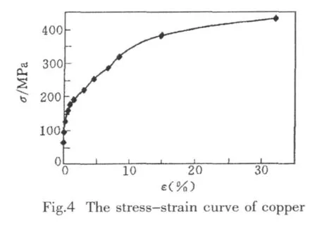
The elastic limit of the annealed copper is 150MPa and the corresponding strain is 518×10-3.The tension ultimate strength is 431MPa,the tension ultimate strain is 3.2×10⁻¹.The initial modulus of elasticity is 66 GPa.When the strain reaches 0.14,the modulus of elasticity decreases to 3GPa[25].

3.2 Mechanics FEM analysis
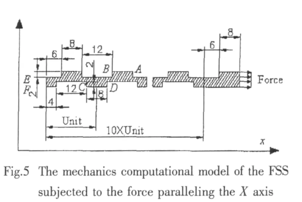
According to the symmetry of the infinite plate,when the force parallels the coordinates axis X,the FEM computational model of the FSS can be established as Fig.5.In this situation,the lines through AB,CD,EF can be considered as the symmetry axis of the plate.Furthermore,on these symmetry axes the component of displacement which is normal to these axes will be zero.At the left end of the sample,an evenly distributed force is loaded.10 units of periodic substructures are established.The stress and deformation in the leftmost periodic substructure can be used to simulate those in infinite plate with periodic apertures.
In the same way,when the force parallels the Y axis,the FEM computational model of the FSS can be established as Fig.6.Due to the infinite size of the plate,the lines through AB,CD,EF can be considered as symmetry axes of the plate.On these axes,the component of displacement which is normal to them will be zero.At the up end of the sample,an evenly distributed force is loaded.10 units of periodic substructure are established.The stress and deformation in the bottom periodic substructure can be used to simulate those in infinite plate with periodic apertures
As usual,there is stress concentration phenomenon in the plate.When the value of force is big enough,the parts near the corners of the holes will reach the ultimate strain;then,these parts will crack.Once there are cracks on the corner,there will be many saw teeth on the transmission coefficientfrequency curve and the EM property of FSS will be ruined[26].Although the FSS with cracks can still endure the force,due to this great decrease in the EM property,only the situations with the force smaller than the cracking one are researched here.

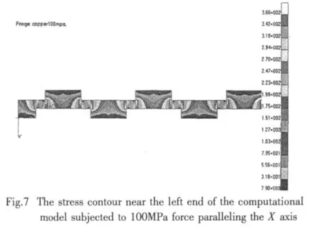

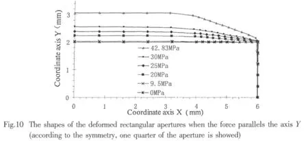
Firstly,a set of forces is established,which form an arithmetic progression.The step between the neighbor forces is small enough.The stress field and deformation field caused by each force are calculated by using FEM.The result shows that the stress distribution is periodic.The stress distribution in the leftmost periodic substructure is the same with the substructures nearby(Fig.7,Fig.8).So,the 10 units of periodic substructures succeed in making the leftmost periodic substructure simulate the periodic substructure in infinite plate.Then,the deformation fields are picked out,of which the corresponding maximum stresses equal the yield strength,ultimate strength and the stresses at which the elasticity modulus change greatly.By processing these deformation fields,the shape and size of aperture,distance and spatial relative angle between apertures are gotten.All these are in the form of data(Fig.9,Fig.10,Tab.1,Tab.2)in order to build a electromagnetics FEM computational model.

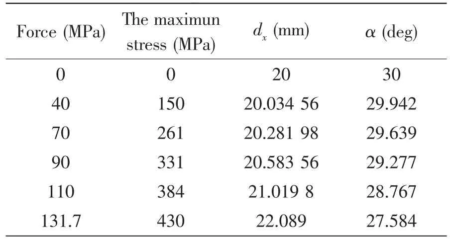
Tab.1 The distances and spatial relative angles between apertures when the force parallels the X axis
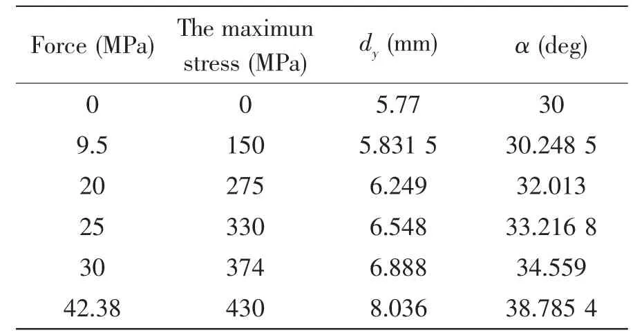
Tab.2 The distances and spatial relative angles between apertures when the force parallels the Y axis
In the situation that force parallels the X axis,when the force reaches 40 MPa,the maximum stress which occurs near the corner of the aperture reaches the limit of elasticity 150 MPa;when the force reaches 131.7 MPa,the maximum stress reaches ultimate strength and the corner of aperture starts to crack.
In the situation that force parallels the Y axis,when the force reaches 9.5 MPa,the maximum stress which occurs near the corner of the aperture reaches the limit of elasticity 150 MPa;when the force reaches 42.38 MPa,the maximum stress reaches ultimate strength and the corner of aperture starts to crack.
3.3 Electromagnetics FEM analysis
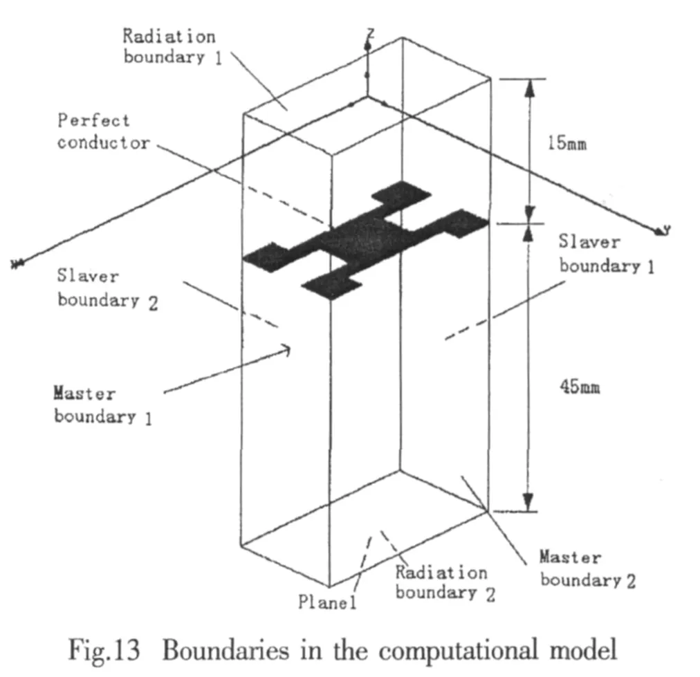
According to the geometry parameters of the FSS deformed by force,which are gotten through mechanics FEM calculation,the computational models for the electromagnetics FEM analysis are established.The electromagnetics FEM software used here is HFSS 9.0 from Ansoft.The excitation in the model is a planar wave propagating in the negative Z direction.The direction of E is perpendicular to the longer edge of aperture.The angle of incidence is zero.According to the periodicity of FSS,a unit cell is cut out of the FSS(Fig.11,Fig.12)[27].Two pairs of master and slaver boundaries and two radiation boundaries are defined(Fig.13),the distance between the radiation boundaries is bigger than 1/4 wave length.

For the calculation of each EM wave frequency response of deformed FSS,18-23 frequency points are chosen.In order to ensure the preciseness of calculation,we do not use the frequency sweep technology,in which the geometry model is meshed only once and the calculations of the electromagnetic fields at different frequencies are conducted on the same mesh.For every incident wave at a different frequency,a new adaptive mesh is conducted.The delta E which is used as stopping criteri on for adaptive solution is set as 0.05.In the situation with frequency near the resonant one,the total number of elements reaches 30 000-60 000.In other situations,the total number of elements is between 5 000-8 000.
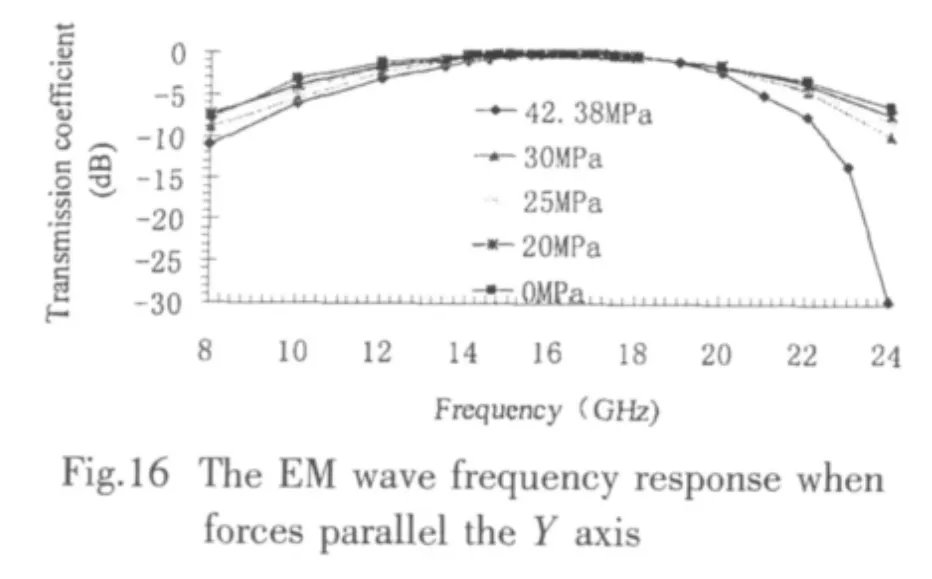
The mechanics calculation shows that the deformation of aperture is rather small when the maximum stress in the stress concentration area is smaller than the elasticity limit.So,the EM property of FSS in this stress status can be considered approximately same as the FSS not subjected to force.Thus,9 situations are calculated(Tab.3).The corresponding EM wave frequency responses are showed in Figs.14-17.
Calculation of transmission coefficient is based on the ratio of transmitted and incident power as

Tab.3 9 situations calculated in the EM research

The plane1 in formula(5)is the bottom surface of the air box in Fig.13.is the normalized vector paralleling the axis Z of coordinates.


4 Discussion
The influence of force on the EM wave frequency response of FSS can be described as follows:
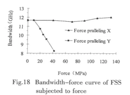
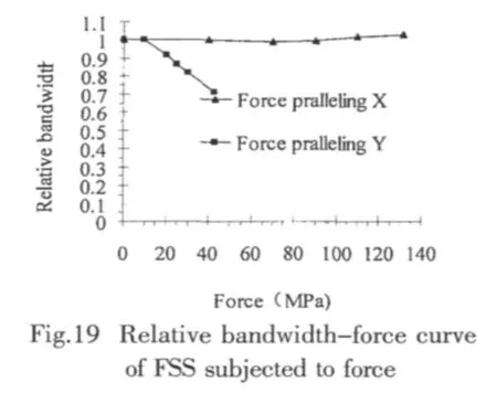
(1)The force loaded on the FSS will cause the bandwidth to change.The bandwidth discussed here is the one corresponding to the transmission coefficient above-3dB.When the direction of force parallels the shorter edge of aperture,the bandwidth will become narrow.When the direction of force parallels the longer edge of aperture,the bandwidth will become broader.When the force paralleling the shorter edge of the aperture reaches 42.38 MPa,the bandwidth decreases from original 11.65GHz to 8.24GHz.The bandwidth after deformation is 70.7 percent of the initial one(Fig.18,Fig.19).When the force paralleling the longer edge of the aperture reaches the 131.7 MPa,the bandwidth increases to 12.014GHz.The bandwidth is 103.1 percent of the initial one(Fig.18,Fig.19).
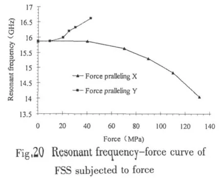

(2)The force loaded on the FSS will cause the resonant frequency to change.The resonant frequency will move to a higher frequency when the direction of force parallels the shorter edge of aperture;the resonant frequency will move to a lower frequency when the direction of force parallels the longer edge of aperture.When the force paralleling the shorter edge of the aperture reaches 42.38 MPa,the resonant frequency moves from original 15.86GHz to 16.61GHz,the movement is 0.747GHz(Fig.20,Fig.21).When the force paralleling the longer edge of the aperture reaches the 131.7 MPa,the resonant frequency moves from original 15.86GHz to 14.058GHz,the movement is-1.806GHz(Fig.20,Fig.21).(3)When the magnitude of force paralleling X axis is smaller than 40MPa,the corresponding maximum stress is smaller than the elasticity limit which is 150MPa;the FSS is in the status of elasticity.In this situation,the deformation of aperture is unobvious(Fig.9,Tab.1),the EM property of FSS alters indistinctively.When the force paralleling X axis is bigger than 40MPa,the maximum stress is bigger than the elasticity limit and the parts in the stress concentration areas near corners get into the nonlinear stage.In this situation,as the growing of the magnitude of force,the deformation of aperture becomes prominent and the EM property of FSS changes greatly.It can be seen that the plastic deformation in the stress concentration area is the main part of the deformation of aperture and is the key aspect responsible for the altering of the EM property of FSS.The periodic apertures weaken the strength of FSS.These apertures make FSS get into the nonlinear stage rather early when force is loaded on it.This means a minor force can cause the EM property of FSS to change.
(4)The change of the EM property of FSS is sensitive to the direction of the force.For the sample here,the ratio of the EM property deviation to the change of magnitude of force is bigger when the force parallels the shorter edge of aperture.However,this ratio is smaller when the force parallels the longer edge of aperture.When the force parallels the shorter edge of aperture,the slope of the bandwidth-force curve is 0.089 94GHz/MPa at 9.5MPa.But,this slope is 0.004 076GHz/MPa at 40 MPa when the force parallels the longer edge of aperture(Fig.18).The former is 22.1 times of the latter.The slope of the resonant frequency-force curve is 0.011 318GHz/MPa at 9.5MPa when the force parallels the shorter edge of aperture.But,this slope is 0.008 084GHz/MPa at 40 MPa when the force parallels the longer edge of aperture(Fig.20).The former is 14 times of the latter.
5 Conclusions
Through the mechanical analysis and numerical investigation,the conclusion can be summarized as follows:
(1)When the force is loaded onto the FSS,the EM property of FSS will alter due to the deformation of the shape of aperture,the change of the distance between apertures and the change of relative spatial angle between apertures.The change of EM property of FSS lies in two aspects:(a)bandwidth,(b)resonant frequency.These changes of EM property can not be ignored.
(2)The change of the EM property of FSS is sensitive to the direction of the force.As for the sample in this research,when the force parallels the shorter edge of rectangular aperture,the EM property of FSS changes greatly with the increase of the force.
(3)Holes in the FSS are quite different from the holes in the thin plate used purely for the structure component.The corners of the holes in the thin plate used purely for the structure component are designed to be round.However,the corners of the holes in FSS are sharp.This characteristic makes the strength of FSS much lower.The lower ability to bear force causes the FSS to get into plastic status rather early.This will cause significant deformation which is responsible for the altering of the frequency response of FSS.Thus,the corners of apertures can be designed to be round ones so as to reduce the influence of the force on the EM property.However,this will change the resonant frequency due to the change of the shape of aperture.Nowadays,except the circular apertures,all the apertures in FSS are designed to be the ones with sharp corner.And,researches on the EM property of FSS are mainly conducted on the FSS with this kind of sharp-cornered aperture.So the EM property of FSS with round-cornered apertures needed to be researched.
(4)The altering of frequency response of FSS is sensitive to the direction of the force which is loaded on the FSS.Thus,the disposal of the FSS should ensure the direction,in which the forces are loaded,to avoid the ones which may make greater influence occur.
[1]Mittra R,Chan C H,Cwik T.Techniques for analyzing frequency selective surfaces-A review[J].Proceedings of the IEEE,1988,76(12):1593-1615.
[2]Munk B A.Frequency selective surface-theory and design[M].Wiley Publishing Inc,New York,2000.
[3]Xing Liying.Study on the microwave-absorbing composite with circuit analogue[D].Beijing:Aircraft and Aviation University,2003.(in Chinese)
[4]Xing Liying.Stealthy material[M].Beijing:Chemistry Industry Press,2004:140-141.(in Chinese).
[5]Jose K A,Sha Y,Varadan V,Neo C P.FSS embedded microwave absorber with carbon fiber composite[C]//IEEE Antennas and Propagation Society International Symposium.San Antonio,USA,2002,2:576-579.
[6]Chakravarty S.Synthesis of spatial filters and broadband microwave absorbers using micro-genetic algorithms[D].Pennsylvania:Pennsylvania State University,2003.
[7]Chakravarty S,Mittra R,Williams N R.Application of a microgenetic algorithm(MGA)to the design of broadband microwave absorbers using multiple frequency selective surface screens buried in dielectrics[J].IEEE Transactions on Antennas and Propagation,2002,50(3):284-296.
[8]Chakravarty S,Mittra R,Williams N R.Application of micro-genetic algorithm(MGA)to the synthesis of broadband microwave absorbers comprising multiple frequency selective surfaces embedded in dielectric and magnetic media[C]//IEEE Antennas and Propagation Society International Symposium.Boston,USA,2001,4:692-695.
[9]Sha Y,Jose K A,Neo C P,Varadan V K.Experimental investigations of microwave absorber with FSS embedded in carbon fiber composite[J].Microwave and Optical Technology Letters,2002,32(4):245-249.
[10]Chao C C.Transmission of microwave through perforated flat plates of finite thickness[J].IEEE Transactions on Microwave Theory and Techniques,1973,21(1):13-18.
[11]Calif S D.R&D work in low observables shifts emphasis from coatings to structures[J].Aviation Week and Space Technology,1989,131(12):109-112.
[12]Chao C C.Transmission through a conducting screen perforated periodically with aperture[J].IEEE Transactions on Microwave Theory and Techniques,1970,18(9):627-632.
[13]Chao C C.Diffraction of electromagnetic waves by a conducting screen perforated periodically with circular holes[J].IEEE Transactions on Microwave Theory and Techniques,1971,19(5):475-481.
[14]Luebbers R,Munk B.Cross polarization losses in periodic arrays of loaded slots[J].IEEE Transactions on Antennas and Propagation,1975,23(2):159-164.
[15]Zarrillo G,Aguiar K.Closed-form low frequency solutions for electromagnetic waves through a frequency selective surface[J].IEEE Transactions on Antennas and Propagation,1987,35(12):1406-1417.
[16]Lambea M,Gonzalez M A,Encinar J A,Zapata J.Analysis of frequency selective surfaces with arbitrarily shaped apertures by finite element method and generalized scattering matrix[C]//IEEE Antennas and Propagation Society International Symposium.Newport Beach,USA,1995,3:1644-1647.
[17]Luebbers R,Munk B.Some effects of dielectric loading on periodic slot arrays[J].IEEE Transactions on Antennas and Propagation,1978,26(4):536-542.
[18]Lambea M,Encinar J A.Analysis of multilayer frequency selective surfaces with rectangular geometries[C]//Ninth International Conference on Antennas and Propagation.Eindhoven,Netherlands,1995,1:528-531.
[19]Lima A C C,Parker E A,Langley R J.Tunable frequency selective surface using liquid substrates[J],Electronics Letters,1994,30(4):281-282.
[20]Caroglanian A,Webb K J.Study of curved and planar frequency-selective surfaces with nonplanar illumination[J].IEEE Transactions on Antennas and Propagation,1991,39(2):211-217.
[21]Manara G,Monorchio A,Mittra R.Frequency selective surface design based on genetic algorithm[J].Electronics Letters,1999,35(17):1400-1401.
[22]Ohira M,Deguchi H,Tsuji M,Shigesawa H.Multiband single-layer frequency selective surface designed by combination of genetic algorithm and geometry-refinement technique[J].IEEE Transactions on Antennas and Propagation,2004,52(11):2925-2931.
[23]Weile D S,Michielssen E.The use of domain decomposition genetic algorithms exploiting model reduction for the design of frequency selective surfaces[J].Computer Methods in Applied Mechanics and Engineering,2000,186:439-458.
[24]Chakravarty S,Mittra R.Application of the micro-genetic algorithm to the design of spatial filters with frequency-selective surfaces embedded in dielectric media[J].IEEE Transactions on Electromagnetic Compatibility,2002,44(2):338-346.
[25]Hao Juntao,Yue Yaozhen,Lu Xiaobing,Jia Jingsheng,Qu Yang,Sun Jingang.Experimental study on mechanical properties of copper waterstop in CFRD[J].Journal of Hydraulic Equipments,2000,10:18-21.(in Chinese)
[26]Xie Wenjiao,Wu Zhe.Experimental investigation into frequency characteristics of FSS basic aperture cell[J].Journal of Airplane Design,2003,3:51-54.
[27]Bardi I,Remski R,Perry D,Cendes Z.Plane wave scattering from frequency-selective surfaces by the finite-element method[J].IEEE Transactions on Magnetics,2002,38(2):641-644.

- 船舶力学的其它文章
- Generation and Propagation of Nonlinear Surface Waves in a Fully-Nonlinear Wave Flume
- Nonlinear Model Predictive Controller Design for Path Following of Underactuated Ships
- Dynamic Modeling and Optimization Design on Underwater Gliders
- Factors Affecting the Slamming Pressure Peak Value of Trimaran Cross Structure
- Damage Detection for Offshore Platform by Wavelet Transform
- Study on Multi-objective Optimization and Multi-attribute Decision Making of Dynamic Vibration Absorber