
Mechanical properties of 65Mn chiral structure with three ligaments
2019-11-28 08:42SuZhuZhengTomovic
Acta Mechanica Sinica 2019年1期
X. W. Su·D. M. Zhu·C. Zheng·M. M. Tomovic
Abstract Chiral honeycomb structures have been developed in recent years,showing excellent mechanical properties,including in-plane deformation and out-of-plane bearing and vibration isolation. In this study, the 65Mn chiral structure with three ligaments was modeled and analyzed using the finite element (FE) method. The effects of the dimensionless ligament length and dimensionless ligament thickness on the in-plane equivalent elastic modulus, equivalent Poisson's ratio, and out-of-plane shear modulus were studied. The numerical results indicate that increase of the dimensionless ligament length leads to decrease of the equivalent elastic modulus and increase of the equivalent Poisson's ratio,whereas the out-of-plane equivalent shear modulus decreases.The results also indicate that increase of the dimensionless ligament thickness leads to increase of the equivalent elastic modulus,whereas the equivalent Poisson's ratio remains nearly unchanged and the out-of-plane equivalent shear modulus shows a linear increase.The numerical results are verified by comparison with published experimental data.These results will provide a reference for the application of chiral structures with three ligaments in the aerospace field.
Keywords Chiral structure with three ligaments·Mechanical properties·Finite element method
1 Introduction
To meet the increasingly stringent requirements of many structural applications, e.g., in the aerospace and nuclear powerfields,etc.,manyspecialstructureshavebeendesigned and their effects on system performance studied[1,2].The hexagonal aluminum honeycomb sandwich is one such novel structure that has seen increasing use for design of satellite platforms.To meet technical specifications in terms of high load performance, vibration-suppression devices are often used at locations such as the vibration source,transfer path,and payload mounting surface, to improve the mechanical environment under high loads [2]. However, this approach increases the complexity and weight of the satellite system, while its effective working range is relatively limited.Chiral structures offer lower weight, larger in-plane deformation,higher out-of-plane load capacity,and better impact resistance. The performance of such structures in terms of vibration and sound insulation is excellent,while their design sensitivity is high[3-5].In addition,adjusting the geometric parameters of the chiral structure can result in mechanical properties that satisfy the desired structural requirements of the designed system.A chiral structure is formed from hollow cylinders (nodes), and ligaments which are tangent to them.The geometric parameters of the cylinder and ligament,specifically the number and arrangement of the ligaments,will affect the mechanical properties of the resulting chiral structure. Because of the complexity of the shape of such honeycomb sandwich structures, it is necessary to simplify correspondingmechanical models toacertainextent byusing an equivalent in analyses and calculations[6,7].

Fig.1 Geometric model and parameters:a 3D geometric model,b geometric parameters
The beneficial characteristics of chiral structures have prompted many researchers to study their mechanical properties.The mechanical properties of deformable honeycomb structures were analyzed by Zhao [8], comparing the Poisson's ratio, Young's modulus, and shear modulus of chiral honeycomb structures with six ligaments, four ligaments,and reverse four ligaments. The influence of the use of a chiral honeycomb as the core structure on the performance of a wing structure and its deformation capacity when not exceeding the yield strength was verified by Spadoni et al.[9].The relationship between the in-plane Poisson's ratio and the elastic modulus of a composite chiral structure with five ligaments and different geometric parameters was studied by Alderson et al. [10]. Meanwhile, using analytical solutions and finite element(FE)analysis,Miller et al.[11]studied the plane buckling optimization and flat pressure performance of honeycomb structures with six or four ligaments,and Alderson et al.[12]studied the in-plane linear elastic constants of a composite chiral structure with three ligaments.In addition,Lorato et al. [13] studied the transverse Young's modulus and transverse shear stiffness of chiral structures with three,four, or six ligaments based on FE analysis. The external shear properties of a chiral structure with six ligaments and a biological composite core were studied by Cicala et al.[14],and Chen et al.[15]analyzed the in-plane and out-of-plane elastic modulus using numerical simulations and conducted experiments on a chiral structure with a reverse four-ligament configuration having negative in-plane Poisson's ratio and anisotropy. The elastic modulus and shear modulus of sixand four-ligament structures were studied by Bacigalupo and Gambarotta[16],who also conducted numerical simulations using the homogenization method.The effect of a disordered structure on the mechanical properties of honeycombs with six ligaments was studied by Mizzi et al.[17]using the FE method.
Chiral honeycomb structures have additional advantages,including the fact that the transverse shear strength and outof-plane compressive strength can be controlled by adjusting the material as well as the geometric parameters of the ligaments and hollow cylinders[18-20].By choosing different geometric parameters,desired values of mechanical properties such as the Young's modulus,Poisson's ratio,and shear modulus of the structure can be achieved. Therefore, the mechanical properties of a chiral honeycomb structure can be optimized and improved by selection of the structure's parameters.
This paper presents the influences of the geometrical parameters of the 65Mn chiral structure with three ligaments on its mechanical properties. The 65Mn chiral structure has the characteristics of both a spring steel and honeycomb structure. The variation of the out-of-plane modulus,Poisson's ratio, and shear modulus of the chiral structure with three ligaments was studied by changing geometric parameters such as the node (middle cylinder) radius, ligament length,and ligament thickness.Section 1 presents the in-plane mechanical properties. Section 2 presents the outof-plane mechanical properties.The results presented in this paper provide a reference for research and application of such chiral structures in the aerospace field.
2 In-plane mechanical properties
The three-dimensional(3D)geometric model and geometric parameters of the chiral structure with three ligaments are shown in Fig. 1, where r is the radius of the node (outer diameter), R is the node spacing, L is the ligament length,t1is the node thickness,t is the ligament thickness,and b is the thickness of the structure(Z-direction).To facilitate the study,the parameters are expressed in dimensionless terms,namely as a dimensionless ligament length α = L/r and dimensionless ligament thickness β =t/r.
2.1 Calculation model verification

Fig.2 Geometric model,constraints,and grid of nodes.a Geometric model,b constraints along Y-direction,c constraints along X-direction,and d FE mesh
Experimental data for chiral structures with three ligaments are commonly used to verify calculation models[10]. The structural parameters are as follows: material density 970 kg/m3, Poisson's ratio 0.28, Young's modulus 1.6 GPa, yield stress 44 MPa, node radius 5 mm, node thickness 1.5 mm, ligament length 25 mm, ligament thickness 1.5 mm,and structural thickness(distance between two planes)25 mm.
An FE model for the finite-period chiral structure with three ligaments was established using the ABAQUS/standard model. The structure has three cell elements in horizontal direction and three in vertical direction,hence the structure ratio (X vs. Y) is 1 [21]. The entire model was built in In ABAQUS/CAE using two-dimensional shell elements, and divided into a grid.Initially,the entire model was set up in the part module,then the grid was divided in the mesh module.The geometric model,constraint model,and schematic diagram of the grid for the chiral structure with three ligaments are shown in Fig.2.Displacement loads were applied in Xand Y-direction,respectively.
In Y-direction,the strain uyis 2%,and the displacement of the edge of each node Y1-Y6, in Fig. 2b, in Y-direction is 0.00125 m. The X-direction displacement of the edge of nodes Y2and Y5is 0.The rotation around the Z-axis is 0.
In X-direction,the strain uxis 2%,and the displacement of the edge of each node X1-X8, in Fig. 2c, in X-direction is 0.001299 m.The Y-direction displacement of the edge of nodes X2,X3,X6,and X7is 0.The rotation around the Z-axis is 0.
A contour plot of the stress in X-and Y-direction obtained from the finite element analysis(FEA)simulation is shown in Fig.3,in units of Pa.
From Fig.3,it can be seen that,when the Y-direction displacement is applied,the nodes rotate and move up or down.The joints between the nodes and ligaments are subjected to the combined action of bending and tension or compression,and the resulting deformation is significant.The stress is primarily concentrated at the tangent point between the node and ligament,while the stress distribution is uniform.When displacement is applied in Y-direction,the nodes rotate and move left or right,the deformation is increased,and the stress distribution is uneven.

Fig.3 Stress contour plot
The formulas for calculating the equivalent modulus of elasticity and the equivalent Poisson's ratio for the chiral structure with three ligaments are as follows[22]:
The equivalent elastic modulus can be computed from

The stress can be determined from

The cross-sectional area can be computed from

where i represents x or y, n is the number of the node, F is the nodal reaction,b is the structure's thickness, Liis the structural length along X-or Y-direction in Fig.2a,and εiis the 2%strain.
The equivalent Poisson's ratio can be computed from

The strain can be determined from

where i, j represent x or y,respectively,li,l j represent the length after deformation along X-and Y-directions,respectively,and l0i,l0jrepresent the length prior to deformation along X-and Y-directions,respectively,in Fig.2a.
After loading along Y-direction, the forces on the nodal edges Y1,Y2,and Y3are determined to be

The equivalent elastic modulus in Y-direction,calculated from Eqs.(1)-(3),is determined to be 0.8345 MPa.The Poisson's ratio in Y-direction determined from Eqs. (4) and (5)has a value of 0.7478.
After loading along the X-direction,the forces at the nodal edges X1,X2,X3,and X4are determined to be

The equivalent elastic modulus in X-direction is determined from Eqs. (1)-(3), yielding a value of 1.2460 MPa.The Poisson's ratio for the X-direction is determined from Eqs.(4)and(5),having a value of 0.7057.
The results of the numerical simulation versus published experimental results are presented in Table 1.
It can be observed that the results of FEA closely match the experimental values.The relative errors of the elastic mod-ulus along the X-and Y-directions are 0.32%and 11.22%,respectively, while the relative errors of the Poisson's ratio for the X-and Y-directions are 2.28%and 13.31%.Hence,it can be concluded that the FEA is accurate to a significant degree.

Table 1 Results of numerical simulations and the test data
2.2 Effect of structural parameters on the equivalent elastic modulus and Poisson's ratio
The chiral honeycomb structure is a new type of multifunctional honeycomb structure, and by choosing different geometric parameters,different values of the equivalent elastic modulus and Poisson's ratio can be achieved.
2.2.1 Dimensionless ligament length α
The structure material is 65Mn with density of 7820 kg/m3,the Poisson's ratio is 0.288,the Young's modulus is 211 GPa,and the yield stress is 1560 MPa.The geometric parameters analyzed in this study are presented in Table 2.
In Y-direction,the strain uyis 2%,and the displacement of the edge of each node Y1-Y6in Fig.2b,along Y-direction is shown in Table 3.The X-direction displacement of the edge of nodes Y2and Y5is 0.The rotation of the structure around the Z-axis is 0.
In X-direction,the strain uxis 2%,and the displacement of the edge of each node X1-X8in Fig.2c,along X-direction is shown in Table 3.The Y-direction displacement of the edge of nodes X2,X3,X6,and X7is 0.The rotation of the structure around the Z-axis is 0.
The displacements for different values of the dimensionless ligament length are presented in Table 3.
The parameters used for determining the equivalent elastic modulus along the Y-direction, for different values of the dimensionless ligament length α, are presented in Table 4.The parameters include forces F1, F2,and F3and the crosssectional area Ac/S,as obtained from Eq.(3).
The parameters for calculating the equivalent elastic modulus along X-direction for different values of the dimensionless ligament length α are presented in Table 5. The parameters include the forces F1, F2, F3, and F4, and the cross-sectional area Ac/S,as obtained from Eq.(3).
The parameters for calculating the Poisson's ratio along Y-directionfordifferentvaluesofthedimensionlessligament length α are presented in Table 6.The parameters include the lengths lx,lyalong the X-and Y-direction after deformation,and the strain εx,εyalong the X-and Y-directions,obtained from Eq.(4).
The parameters for calculating the Poisson's ratio along X-directionfordifferentvaluesofthedimensionlessligament length α are presented in Table 7.The parameters include the lengthslx,lyalong the X-and Y-directions after deformation,and the strain εx,εyalong the X-and Y-directions,obtained from Eq.(4).
The equivalent elastic modulus and Poisson's ratio, for different values of the dimensionless ligament length,were determined from Eqs. (1) and (4), based on the data in Tables 4-7.The results are shown in Fig.4.
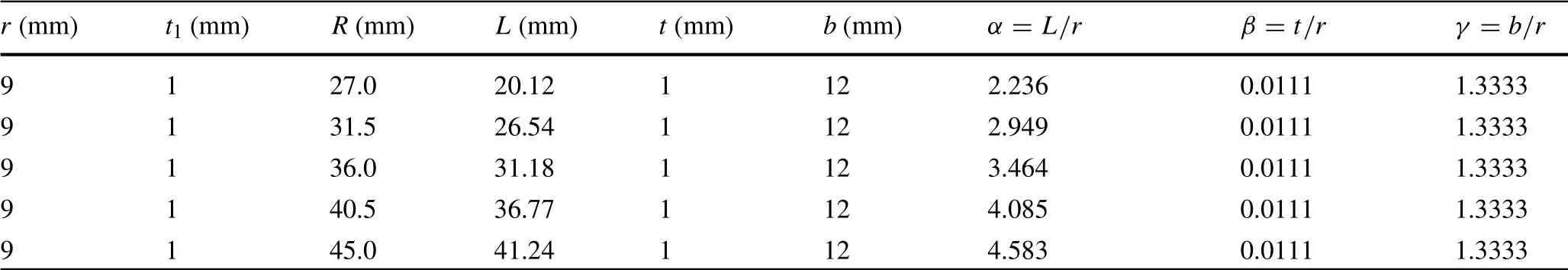
Table 2 Geometric parameters

Table 3 Displacement values(m)for different values of α

Table 4 Parameters for calculating the equivalent elastic modulus along Y-direction

Table 5 The parameters for calculating Ex

Table 6 Parameters for calculating vyx

Table 7 Parameters for calculating vxy

Fig.4 Equivalent elastic modulus and Poisson's ratio for different α.a Equivalent elastic modulus,b equivalent Poisson's ratio

Table 8 Parameters for calculating Ey

Table 9 Parameters for calculating Ex

Table 10 Parameters for calculating the Poisson's ratio along Y-direction vyx
These results indicate that,with increase in the dimensionlessligamentlength,theequivalentelasticmodulusdecreases whereas the equivalent Poisson's ratio increases in Fig.4.
2.2.2 Dimensionless ligament thickness β
The radius of the node(outer diameter)r is 9 mm,the node spacing R is 45 mm,the ligament length L is 41.24 mm,and the thickness b of the structure(Z-direction)is 12 mm.The node thickness t1and the ligament thickness t are 0.5 mm,0.8 mm,1.0 mm,1.2 mm,and 1.5 mm,respectively,while the dimensionless ligament thickness β is 0.056, 0.089, 0.111,0.133,and 0.167,respectively.
In Y-direction,the strain uyis 2%,and the displacement of the edge of each node Y1-Y6in Fig.2b,is 0.00225 mm.The X-direction displacement of the edge of nodes Y2and Y5is 0.The rotation around the Z-axis is 0.
In X-direction,the strain uxis 2%,and the displacement of the edge of each node X1-X8in Fig.2c,in X-direction is 0.0023382 mm.The Y-direction displacement of the edge of nodes X2,X3,X6,and X7is 0.The rotation around the Z-axis is 0.
The parameters for calculating the equivalent elastic modulus along Y-direction for different values of the dimensionless ligament thickness β are presented in Table 8.The parameters include the forces F1,F2,and F3,while the crosssectional area Ac/S is obtained from Eq.(3).The length Lxalong the X-direction is 0.234 m.
The parameters for calculating the equivalent elastic modulus along the X-direction, for different values of the dimensionless ligament thickness β, are presented in Table 9. The parameters include the forces F1, F2, F3,and F4, while the cross-sectional area Ac/S is obtained from Eq. (3). The length L y along the Y-direction is 0.225 m.
The resulting strains εx,εyalong the X-and Y-directions,as determined from Eq. (4), are presented in Table 10. The lengthl0xandl0yalong the X-and Y-directions,before deformation,are 0.0779 m and 0.1350 m,respectively.The lengths lx, lyalong the X- and Y-directions after deformation are 0.0884 m and 0.1326 m,respectively.
The parameters for calculating the Poisson's ratio along the X-direction, for different values of the dimensionless ligament length α, are presented in Table 11. The parameters include the lengths lxand lyalong the Xand Y-directions after deformation, and the strains εxand εyalong the X- and Y-directions, as determined from Eq.(4).
The resulting equivalent elastic modulus and Poisson's ratio, for different dimensionless ligament lengths, can be calculated by Eqs.(1)and(4)based on the results presented in Tables 8-11.The results for the equivalent elastic modulus and Poisson's ratio are shown in Fig.5.
The results in Fig. 5 indicate that the equivalent elastic modulus increases gradually with increase in the dimensionless ligament thickness, β, and that the equivalentelastic modulus in the X-direction is larger than that in the Y-direction. The results also indicate that the equivalent Poisson's ratio remains fairly constant with increase of the dimensionless ligament thickness, and that the equivalent Poisson's ratio along the X-direction is larger than in the Y-direction.

Table 11 Parameters for calculating vxy

Fig.5 Equivalent elastic modulus and Poisson's ratio as functions of β.a Equivalent elastic modulus,b equivalent Poisson's ratio
3 Out-of-plane mechanical properties
3.1 Model verification
The effectiveness of the finite element method was verified by comparison with published experimental data for a chiral cellular structure with three ligaments[12].The density of the experimental material was 1050 kg/m3,the Poisson's ratio was 0.394, the Young's modulus was 1 GPa, and the yield strength was 50 MPa.The nodal radius r was 10 mm,the nodal thickness t1was 1.5 mm,the ligament length was 25 mm, the ligament thickness of node t was 1.5 mm, and the thickness of the structure was 10 mm.
The ABAQUS/Standard linear model was used to establish the model. The 3D solid was developed in the part module, while the hexahedral mesh was created using the mesh module.
The geometric model,constraints,and schematic diagram of the grid are shown in Fig.6.Pe1-Pe6are planes parallel to the Z-axis,and Pe6describes that very plane.
All the degrees of freedom on the lower surface Pd are constrained,as well as the displacement in Z-direction from plane Pe1to Pe6in Fig. 6b. The displacement of plane Pu along the X-direction is 0.01 mm, while the displacement along the Y-direction and the rotation around Z are 0.
The contour plots of the stress(Pa)and displacement(m)obtained from the numerical simulations are shown in Fig.7.
The formulas used to calculate the equivalent shear modulus,shear strain,shear stress,and area are as follows:Equivalent shear modulus:

Shear stress:

Shear strain:

Area:


Fig.6 Geometric model,constraints,and schematic diagram of mesh.a Geometric model,b constraint,c grid model,d FEA mesh

Fig.7 Stress and strain contour plots.a Stress,b displacement
The reaction force obtained from the simulation is 98 N. The shear strain is 0.002 in Eq. (8), and the area is 5434.3 mm2in Eq. (9). The equivalent shear mod-ulus obtained from the FEA analysis is 18 MPa using Eq. (6), whereas the published experimental value is 16.3 MPa. It can be concluded that the FEA result closely matches the experimental value [12]. The relative error between the numerically obtained value and experimental value is 9.2 % [12], validating the accuracy of the FEA model.

Table 12 Geometric parameters
3.2 Effect of the geometric parameters on the out-of-plane equivalent shear modulus
By choosing different geometric parameters,the chiral honeycomb can exhibit different equivalent shear modulus, as discussed in the following sections.
3.2.1 Dimensionless ligament length α
The geometric parameters are presented in Table 12.
All degrees of freedom on the lower surface Pd are constrained, as well as the displacement in Z-direction from plane Pe1to Pe6in Fig.6b.The displacement along the Xdirection of plane Pu is 0.01 mm,whereas the displacement along the Y-direction and the rotation around Z-axis are 0.
The equivalent shear modulus for different values of the dimensionless ligament length is shown in Fig. 8. The results indicate that the out-of-plane equivalent shear modulus decreases with increase of the dimensionless ligament length. It can also be observed that increase in the dimensionless ligament length results in decrease of the stiffness of the three-ligament structure.
3.2.2 Dimensionless ligament thickness β
The radius r of the node(outer diameter)is 9 mm,the node spacing R is 45 mm, the ligament length L is 41.24 mm,and the thickness b of the structure(Z-direction)is 12 mm.The node thickness t1and the ligament thickness t are the same,taking a value of 0.5 mm,0.8 mm,1 mm,1.2 mm,and 1.5 mm,respectively.The dimensionless ligament length α is 4.583,and the dimensionless ligament thickness β is 0.056,0.089,0.111,0.133,and 0.167.
All degrees of freedom on the lower surface Pd are constrained,as well as the displacement in the Z-direction from plane Pe1to Pe6in Fig. 6b. The displacement along the X-direction of plane Pu is 0.01 mm, and the displacement along the Y-direction and the rotation around the Z-axis are both 0.

Fig.8 Equivalent shear modulus for different values of the dimensionless ligament length

Fig.9 Equivalent shear modulus as a function of dimensionless ligament thickness
The equivalent shear modulus for different values of the dimensionless ligament thickness is shown in Fig.9.
These results indicate that the equivalent shear modulus increases almost linearly with increase of the dimensionless ligament thickness.It can be concluded that the stiffness of the three-ligament structure is enhanced with increase of the dimensionless ligament thickness.When α changes to other values,similar results are obtained.
4 Conclusions
An FEA model of a chiral structure with three ligaments was established, and the effects of the dimensionless ligament length and thickness on its in-plane and out-of-plane mechanical properties studied.
The results indicate that,when the dimensionless ligament length increases, the equivalent elastic modulus gradually decreases and the equivalent Poisson's ratio gradually increases. The equivalent elastic modulus and equivalent Poisson's ratio along the X-direction are slightly larger than along the Y-direction. When the dimensionless ligament thickness increases,the equivalent elastic modulus increases gradually,while the equivalent Poisson's ratio remains relatively constant. In addition, the equivalent elastic modulus and equivalent Poisson's ratio along the X-direction are slightly larger than along the Y-direction.
The trends in the stiffness of the structure are opposite with increase of the dimensionless ligament length and thickness.As the dimensionless ligament length increases, the outof-plane equivalent shear modulus decreases up to a point,after which the decreasing trend decelerates.Consequently,the stiffness of the structure decreases. However, the outof-plane equivalent shear modulus increases almost linearly with increase of the dimensionless ligament thickness.As a result,the overall stiffness of the structure is enhanced.
AcknowledgementsThe authors would like to express their appreciation to the Beijing Excellent Talents Training Program (Grant 2014000020124G072)and China Scholarship Council.

- Acta Mechanica Sinica的其它文章
- Instability inspection of parametric vibrating rectangular Mindlin plates lying on Winkler foundations under periodic loading of moving masses
- GRAPHIC ABSTRACT
- Mechanism of wavy vortex and sign laws in flow past a bluff body:vortex-induced vortex
- Study on vibration of dragon wash basin and free surface waves inside
- Spectral measurements of hypervelocity flow in an expansion tunnel
- Quasi-static simulation of droplet morphologies using a smoothed particle hydrodynamics multiphase model