
Nonlinear vibration analysis of a circular micro-plate in two-sided NEMS/MEMS capacitive system by using harmonic balance method
2019-11-28 08:45MiladSaadatmandAlirezaShooshtari
Acta Mechanica Sinica 2019年1期
Milad Saadatmand·Alireza Shooshtari
Abstract In this study, forced nonlinear vibration of a circular micro-plate under two-sided electrostatic, two-sided Casimir and external harmonic forces is investigated analytically.For this purpose,at first,von Kármán plate theory including geometrical nonlinearity is used to obtain the deflection of the micro-plate.Galerkin decomposition method is then employed,and nonlinear ordinary differential equations(ODEs)of motion are determined.A harmonic balance method(HBM)is applied to equations and analytical relation for nonlinear frequency response(F-R)curves are derived for two categories(including and neglecting Casimir force) separately. The analytical results for three cases: (1) semi-linear vibration; (2) weakly nonlinear vibration;(3)highly nonlinear vibration,are validated by comparing with the numerical solutions.After validation,the effects of the voltage and Casimir force on the natural frequency of two-sided capacitor system are investigated.It is shown that by assuming Casimir force in small gap distances,reduction of the natural frequency is considerable.The influences of the applied voltage,damping,micro-plate thickness and Casimir force on the frequency response curves have been presented too.The results of this study can be useful for modeling circular parallel-plates in nano/microelectromechanical transducers such as microphones and pressure sensors.
Keywords Nonlinear vibration·Two-sided MEMS capacitor·Circular plate·Harmonic balance method
1 Introduction
Wide application of nano/microelectromechanical systems(NEMS/MEMS) has made them an attractive subject in recent decades.The key element in many sensors and actuators are flexible micro-plates vibrating beside parallel fixed electrode plates.Both the flexible and fixed electrode plates are electrically conductive;therefore,there is an electromechanical coupling in these capacitive systems and they are well-known as parallel plate capacitors [1]. Apart from micro-plates,micro-beams are also widely used for sensing and actuating purposes in NEMS/MEMS[2-4].
Applied voltage in MEMS parallel plates leads to an electrostatic force, which is a nonlinear attraction force and is inversely proportional to the square of the gap distance.This voltage has an upper limit known as static pull-in voltage.While the micro-plate vibrates in the transduction process,pull-in may occur at a lower voltage than static pull-in voltage, which is called dynamic pull-in voltage [5]. There is more information about static and dynamic pull-in instability in respective works[6,7].
Micro-plates in NEMS/MEMS can be designed in circular[8],rectangular[9],elliptical[10]or annular[5]shapes,and also in terms of the number of fixed electrode plates,both micro-beams and micro-plates may be considered either single-sided or double-sided [3, 11, 12]. Double-sided, or two-side,systems include two fixed electrode plates on both sides of the flexible micro-plate,and they have some advantages compared to one-sided systems.As a sensor,they have more sensitivity,broader bandwidth,a larger stability region[11-13](tolerate more voltage before pull-in instability)and as an actuator,they are more controllable[14].
One of the main goals in developing the NEMS/MEMS devices is size reduction. In two-sided capacitive systems,the gap distance between the plates can decrease and they are also proper for miniaturization.On the other hand,when dimensions decrease and the gap distance between parallel plates decreases,intermolecular forces like Casimir force[10, 15-17] can be effective. Casimir force is a nonlinear attractive force inversely proportional to the fourth power of the gap distance. Previous results show that the effective region for Casimir force is where the gap is larger than 20 nm and for smaller regions,van der Waals force describes the attraction between micro-plates[18].For more information about intermolecular forces, one can refer to physics manuscripts[19].
Besides nonlinear forces, considering geometrical nonlinearity for microstructures yields to nonlinear differential equations in NEMS/MEMS mathematical models. Hence,various analytical and numerical methods have been used for nonlinear vibration analysis in micro-plates and microbeams. Some approximate analytical methods which have been employed by researchers in this area are averaging method[2],multiple time-scales(MTS)[20]and harmonic balance method (HBM) [21]. As opposed to the numerical methods such as finite element [9] or differential quadratic method (DQM) [22], analytical methods are more complicated,but lead to closed form expressions,which include all parameters of design. Hence, parametric study can be easily done by analytical methods.In this paper,we solved the nonlinear vibration problem for the two-sided capacitor by HBM. It has been shown that HBM is an efficient method to find the steady-state responses of a nonlinear vibration problem[23].
As a literature review for the current work, some of the important previous studies are reviewed in the following.
1.1 Major previous works including geometrical nonlinearity in plates(vibration problem based on set of nonlinear partial differential equations(PDEs))
Combination of the plate theory models and Galerkin reduced-order has been an attractive tool for many researchers.For instance,Vogl and Nayfeh[8,24]assumed von Kármán nonlinear plate theory for a prestressed, fully clamped circular micro-plate under electrodynamic actuation in a capacitive micromachined ultrasonic transducer(CMUT).They employed the multi-mode Galerkin method and reduced nonlinear PDEs to a set of nonlinear ordinary differential equations (ODEs). Their static pull-in analysis has been validated by experiments[25].Thereafter,they used MTS method for the first mode of the vibration and achieved the primary resonance response of the system[8].They also discussed the influence of increasing the mode shapes. By applying Galerkin decomposition,a nonlinear static analysis was done and pull-in voltage was obtained for a rectangular MEMS plate by Zhao et al.[26].Batra et al.studied the static pull-in analysis and linear vibration of circular and rectangular plates[15]and elliptical plate[10]with Galerkin method.Their studies included electrostatic and Casimir forces. In Ref.[15],their results show that circular plates can converge by fewer mode shapes in comparison with rectangular plates.Pull-in instability and vibration analysis of prestressed circular micro-plates based on von Kármán nonlinear plate theory have been studied by Wang et al. [16]. In their work, electrostatic and Casimir forces were assumed and they used a shooting method to solve the problem numerically. Thereafter, the influence of the gap, in-plane stress, and Casimir effect on pull-in voltage and natural frequency have been studied. Nonlinear static and dynamic responses of electrically actuated rectangular micro-plates have been reported by Saghir and Younis[9].The model was based on von Kármán plate theory including geometrical nonlinearity. They studied primary and secondary resonance by reduced order method(ROM)and validated their results by COMSOL Multiphysics. Zhang [27] employed principle of virtual work(PVW) to enhance the accuracy of approximate analytical solutions in large deflection problem for clamped circular plates.Different approximate analytical solutions were studied and their accuracies evaluated by comparing with the numericalresults.Anewapproximateanalyticalsolutionwas proposed and shown to have a better accuracy.
1.2 Major previous works in two-sided capacitive systems(vibration problem based on nonlinear ODE)
Some of the pioneer studies about two-sided systems have been reported in Refs. [12, 13, 28, 29]. In these works, the singledegreeoffreedom(1DOF)modelhasbeenusedforthe circular diaphragm of an MEMS microphone.Liu[13]used a lumped element model for a two-sided capacitive MEMS microphone, which was designed and fabricated by Martin[12].Their model included linear and nonlinear stiffness for the diaphragm and a linear damping coefficient caused by the squeezed film.They used HBM in Ref.[29]and MTS method in Ref.[28]for nonlinear analysis under voltage excitation,and also they worked on pull-in instability and nonlinear vibration in the presence of external pressure by HBM[13].
1.3 Major previous works in static and dynamic pull-in of micro-plates(pull-in analysis based on nonlinear PDE)
The combination of Galerkin method and Cardan solution have been used by Zhang and Zhao[4]as a one-mode solution to pull-in analysis of microstructures such as cantilever,clamped-clamped beams and rectangular plates under electrostatic loading.Faris[5]employed a multi-mode Galerkin method to the static analysis of von Kármán nonlinear circular plate under a combination of electrostatic and thermal loading.
Dynamic pull-in was a target of some other studies.Saeedivahdat et al. [6] studied thermal stress effect on pull-in instability and frequency response of a MEMS microphone.Linear classical plate theory(CPT)was applied for a circular diaphragm in presence of acoustic pressure. They used the first four mode shapes of a circular plate and discretized the problem. Static and dynamic pull-in analysis and nonlinear frequency response have been achieved by numerical methods.Talebian et al.[7]used classical plate theory with internal thermal effect and residual stress for an electrostatically actuated rectangular micro-plate. Their analysis included a composition of a step by step linearization method(SSLM)and finite difference method(FDM).
1.4 Major previous works in nonlinear micro-beams and linear classical plate(vibration problem based on one nonlinear PDE)
For micro-beam structures in NEMS/MEMS,for instance in Refs.[2,3],perturbation techniques were helpful for semianalytical solutions.An analytical study has been reported by Jia et al.[2]on a fixed-fixed beam such as a micro-switch.Geometric nonlinearity,one-sided electric and Casimir force,and residual stress were addressed in their model. Perturbation averaging method was used and frequency response has been achieved.Static bifurcation and primary resonance analysis by MTS for a two-sided capacitive micro-beam have been established by Han et al.[3].
The Euler-Bernoulli model of cantilevered piezoelectric energy harvester under parametric and external forces was investigated by Fang et al.[30].They used the single-mode Galerkin method and harmonic balance to find the analytical relation for frequency-response curves.
Microcantilever with a T-shaped tip mass excited by electrostatic loads was attended by Firouzi et al.[31].Equation of motion was derived by the Hamilton principle and Newton method. The nonlinear static response, primary and secondary resonances have been investigated by employing the Galerkin method and perturbation techniques.
Furthermore, combining CPT and MTS has been used for micro-plate vibration[20,32]and for fluid and structure interaction problem [33]. Caruntu and Oyervides [20, 32]considered a one-sided electrically actuated MEMS circular micro-plate under soft AC voltage by frequency near half natural frequency of the plate.Voltage response and pull-in have been studied[32]and frequency response has been reported[20].The solution consisted of two methods,MTS and ROM.In their case study,MTS was in a good agreement with ROM for small deflections where the amplitude was less than 4/10 of the gap.In large deflection,seven terms of the ROM converged to an exact solution.Interaction of fluid and structure on an electrostatically actuated circular diaphragm micropump has been taken into account [33] and MTS has been deployed for the analysis.CPT has been used in this investigation.Linear CPT has been used and explicit expressions werederivedforthevoltage-deflectionofanelectricallyactuated rectangular micro-plate by Li et al. [34]. Their results have been validated by finite element method.

Fig.1 Schematic of flexible micro-plate between two fixed electrodes in an MEMS sensor.a 3D model.b Section of MEMS two-sided condenser sensor like a microphone as in Ref.[28]
Considering all of the previous valuable investigations,micro-plates in double-sided condensers have never been modeled as a continuous system.Herein,we focused on the nonlinear vibration of a circular micro-plate in a doublesided capacitor and employed von Kármán plate theory to describe deflection.The mathematical model includes a linear damping term, two-sided electrostatic force, two-sided Casimir force and a simple harmonic excitation.The objective is to find an analytical solution for the dynamic response of the micro-plate using Galerkin decomposition and harmonic balance method.The results of this study can be useful in modeling circular parallel-plates in nano/micro electromechanical transducers such as microphones and pressure sensors.
2 Governing equations
2.1 Mathematical modeling by von Kármán plate theory
Figure 1 shows a schematic of a circular micro-plate,which is located between two fixed electrode plates.R is the radius,h is the thickness of the micro-plate and d is the gap distance between the micro-plate and the electrode plates.
All plates are electrically conductive, and by applying voltage,two electrostatic forces attract the micro-plate from both sides,symmetrically.Also,when the distance between the plates decreases, the Casimir force, which is an attractive intermolecular force,is considered[14,15].By applying an external excitation, the micro-plate vibrates under twosided electrostatic load, two-sided Casimir load, damping(for example,squeezed film)and external forces(for example,the acoustic pressure in an MEMS microphone[25]).
The PDE of motion for the thin circular isotropic plate,which is shown in Fig.1,can be expressed by von Kármán's plate theory as[35]:

in which two-sided electrostatic force Fe,two-sided Casimir force Fc,linear damping Fdand external force ˆP,are introduced as follows,

Units of all terms on both sides of Eq. (1) are N/m2, sodenotes pressure,which indicates the excitation pressure applied on the diaphragm of a microphone or pressure sensor.
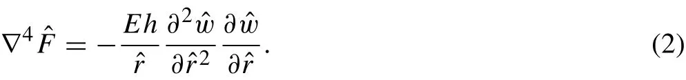
This equation is known as compatibility equation and expresses relations between in-planar displacements in a circular micro-plate.∇4in Eq.(2)denotes bi-harmonic operator and in axisymmetric polar coordinates.It is extracted as the below form:

And eventually,boundary condition equations for the fully clamped circular plate by the immovable condition in the edges is written as in Ref.[36]:

2.2 Nondimensionalization
The following nondimensional parameters are introduced:

It should be mentioned that to show the results in a better view, two nondimensional parameters, ωdand Ω, are considered for the frequency. The first axisymmetric natural frequency for the fully clamped circular plate is ω01=s o in Eq. (4), ωdnormalizes ωpwith respect toand Ω shifts the output from 10.2158 to 1.It will be demonstrated that by using these nondimensional parameters for frequency,primary resonance occurs near to ωd=1.
Substituting parameters that from Eq.(4)into the Eqs.(1)and (2), deflection and compatibility equations are transformed to the below forms,respectively:


in which and the boundary condition equations are rewritten:

2.3 Galerkin decomposition
Equations (5) and (6) describe the transversal vibration of the micro-plate in the double-sided capacitor in the presence of Casimir forces. With the help of the Galerkin method,these PDEs can be reduced to ODEs[35,36].In the Galerkin method, we seek an approximate solution in the form ofin which fi(t)are time-varying coefficients and φi(r)are known as trial functions.Any function that: (1) is differentiable as the order of PDE with respect to r, (2) satisfies boundary conditions, and (3) belongs to a set of linearly independent functions can be used as the trial function. Usually, a set of linear undamped vibration mode shapes of structures are used as trial functions; this procedure is called the multi-mode Galerkin method [15,26, 35]. If a system is excited near the natural frequency of its first mode and no interaction between modes is considered, one can use just the main mode shape as a trial function and neglect higher mode shapes in Galerkin method.This method is called the single-mode Galerkin method[38].Single-mode Galerkin has been used widely in MEMS investigations [2, 39, 40] and was in a good agreement with experiments [34, 35]. Herein, we use φ(r)=(1 - r2)2as the first mode shape of the fully clamped circular plate [6,28].Firstly,we solve compatibility equation for F and then apply Galerkin integral. Considering Eq. (5), electrostatic and Casimir forces are in fractional form nonlinear terms.In the following,we derive the equation of the motion in two different cases,first by considering Casimir forces and next by neglecting it.
2.3.1 Ordinary differential equation of motion by assuming Casimir force
Assuming the following trial function as the main mode shapeof the clamped circular plate:

and letting F(r,t) = f2(t)g(r),Eq.(6)changes to:
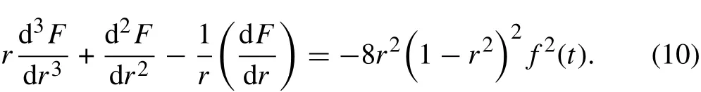
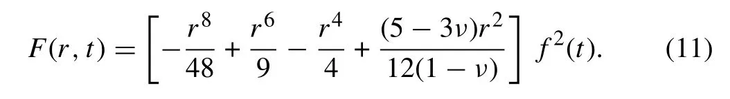
Eliminating f2(t)on both sides of this equation results in a pure ordinary differential equation respect to g(r)that can be solved by the conditions for F given in Eq. (8) and the fact that F must be finite in the all domains of the problem.The solution can be expressed as:
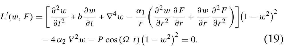
Simplifying the nonlinear terms related to two-sided electrostatic and Casimir forces on the right-hand side of Eq.(5)are shown as:

Multiplying Eq. (5) by (1 - w2)4, it can be rewritten as the following relation:

Now,applying the Galerkin integral in the domain of the problem as follows:

leads to the below nonlinear differential equation respect to f(t):

in which


2.3.2 Ordinary differential equation of motion by neglecting Casimir force
In this case,Fc=0,Eq.(5)changes to the following form:


Again, by assuming Eq. (9) as the trial function and Eq.(11)for the stress function and using the Galerkin integral in a similar way as Sect.2.3.1,the Galerkin procedure can be redone.
By multiplying both sides of Eq. (17) by (1 - w2)2, the equation of motion is rewritten:
The Galerkin integral in the domain of the problem can be applied as:

and gives us the equation of the motion as,

in which


Equation (21) denotes nonlinear differential equation of motion by neglecting Casimir effect.Both Eqs.(15)and(21)include nonlinearity in inertia,damping,stiffness and force terms. These nonlinear terms appear due to the electromechanical-molecular coupling of the system.
It should be noted that Eq.(21)(neglecting Casimir effect in modelling) is completely different from Eq. (15), where Casimir effect had been included in modelling.The denominator of the fractional term in Eq.(5)is(1-w2)4while in Eq.(17)is(1-w2)2.Therefore,Eq.(21)cannot be achieved by eliminating α3in Eq. (15). Therefore, Galerkin integral applied to two different operators to achieve ODEs(Eqs.(14)and(20)).
Another way of dealing with the electromechanical and intermolecular forces is expanding these fractional terms by Taylor series [28]. But for more precision, we multiplied denominators to all terms, then applied the Galerkin integral.
Who rides straight forward shall know both hunger and cold.Who rides to the right shall live, though his steed be dead.Who rides to the left shall die, though his steed shall live.
2.4 Harmonic balance method
To present a semi-analytical solution for Eqs.(15)and(21),the HBM has been used in this paper. HBM is a powerful method for achieving the steady-state response in nonlinear vibration problems[23,29].By using the harmonic balance method the response of the system will be approximated by Fourier series:

where Anand φnare the amplitude and the phase of the n-th harmonic, respectively. In general, using n harmonics in HBM alters the differential equation to a 2n coupled nonlinear equations with respect to Anand φn, which should be solved by a numerical method such as Newton-Raphson[21].In this paper,the first harmonic has been used according to excitation force,and an analytical approach has been considered similar to some previous studies about HBM in Ref.[13]

in which A1and φ1are amplitude and phase of the first harmonic.First-and second-time derivatives are:

2.4.1 HBM for solving equation of motion by neglecting Casimir force
Substituting Eqs.(24)-(26)to Eq.(21)results in:
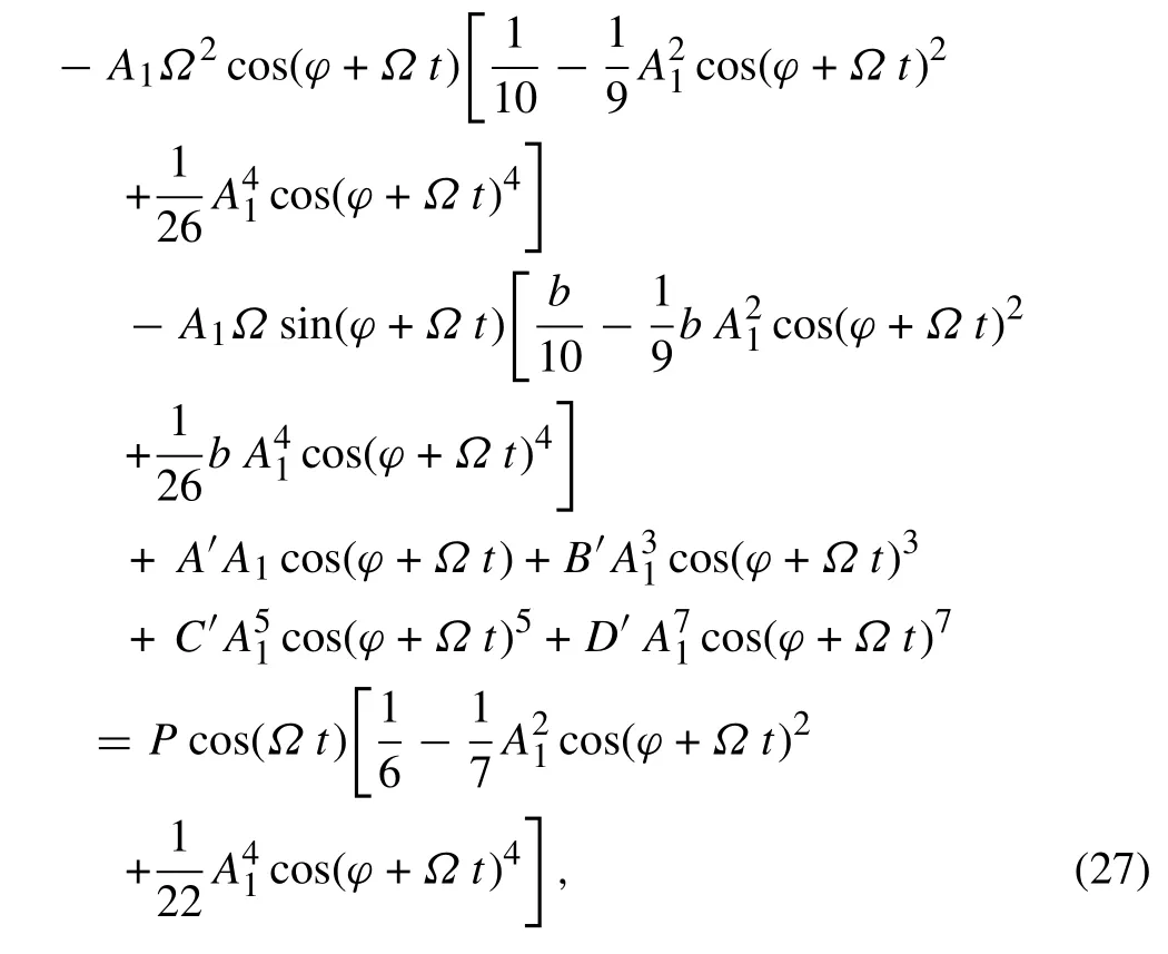
by expanding and multiplying trigonometric functions,holding the first-order terms and neglecting higher-order terms such as cos (2Ωt +···), sin (2Ωt +···), cos (3Ωt +···),sin(3Ωt+···),Eq.(27)will be reduced to the following relation:

Using the following identities:

By collecting the terms which are included sin(Ωt)and cos(Ωt),the result can be expressed as:

in which,

Multiplying the both sides of Eqs.(30)and(31)by sin(φt)and cos(φt),respectively,the summation of them after simplification is:

Next,by adding the both sides of Eq.(33)with Eq.(31),we have:
Again, squaring Eqs. (30) and (31), and adding them to each other yield to:

Now,by using Eq.(34)and below trigonometric identity:

The frequency response relation between A1and ωdcan be obtained,

Equation (34) represents the phase of the response and Eq.(37)by coefficients G′, H′, I′,and J′in Eq.(32)is the implicit relation of magnitude.
2.4.2 HBM for solving equation of motion by assuming Casimir force
Substituting Eqs.(24)-(26)to Eq.(15)results in:
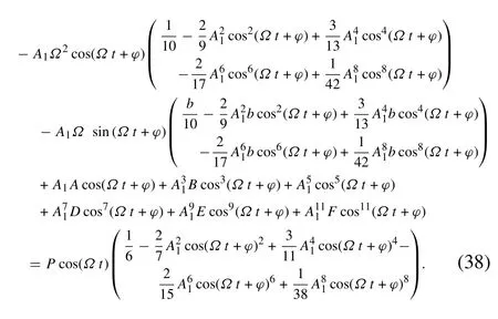
By expanding trigonometric functions in this equation and neglecting higher order terms (cos (2Ωt +···), sin (2Ωt +···),cos(3Ωt+···),sin(3Ωt+···), ···),the Eq.(38)has been reduced to the following relation:
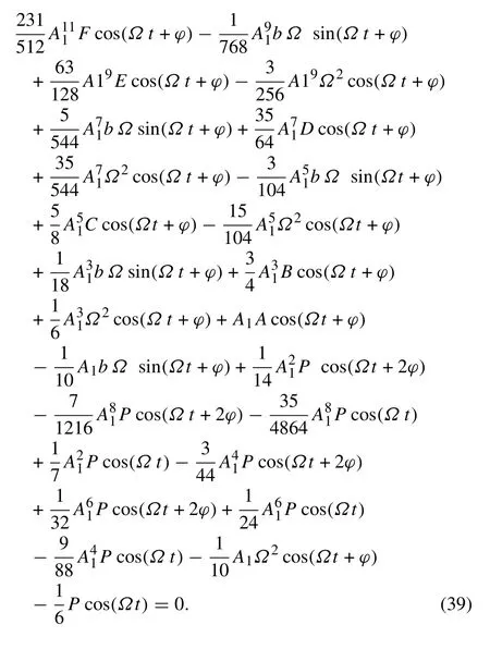
Equation (39) has been expanded by using the identities given in Eq. (29), then by collecting coefficients of sin (Ωt) and cos (Ωt) terms and equaling them to zero,returns:

in whi ch,

It will be observed that Eqs.(40)and(41)are completely similar to Eqs. (30) and (31) in Sect. 2.4.1, respectively.Therefore, it can be concluded by analogy that the phase of the response is:

Similar to Eq. (37), the amplitude of response can be expressed by the following relation:

3 Results and discussion
3.1 Comparison of HBM solution with the numerical method
The equations derived by Galerkin method and HBM for micro-plates are used in this section to study the nonlinear behavior of the system. Firstly, physical specification and geometrical properties of a polysilicon circular micro-plate in a two-sided capacitor have been considered in Table 1.To verify our analytical method, a comparison between Eq. (44) as the harmonic balance solution for the frequency response (F-R) and numerical solutions will bepresented. Herein, Eq. (15) has been solved numerically in several excitation frequencies by using a code in Wolfram Mathematica. In each step the excitation's frequency ωdincreases and then, the equation is numerically solved.After reaching steady-state, the maximum magnitudes are collected as the amplitude of the response in that specified frequency ωd.

Table 1 Physical specifications of an MEMS parallel-plate two-sided capacitor[12]

Fig.2 Comparison between numerical solutions and HBM for nonlinear F-R curves in the various magnitude of excitation
Figure2representsdifferentF-RcurvesobtainedbyHBM and numerical solution in various amplitudes of excitation.Because of the odd-order nonlinear terms in the equation of the system,it is expected that hardening behavior(bending to the right) is observed in large deflection. This nonlinear behavior is due to the nonlinear terms in the equation of motion, which stem from mechanical, electrical and intermolecular coupling. F-R curves are plotted in 100, 200,and 300 Pa. It is seen that the amplitude of the response and hardening behavior increases when the magnitude of the excitationincreases.Thereisanexcellentagreementbetween HBM and the numerical solutions in all regions below 2/3 of the gap.In larger deflections,the higher-order harmonics can be effective,and there is a negligible difference between analytical methods and numerical solutions in resonance regions.

Fig.3 Comparison between the numerical solution and HBM for semi-linear in the small deflection case. a Time-histories of the micro-plate's vibration in P=100 Pa and ωd=0.9 before resonance.b Time-histories of the micro-plate's vibration in P=100 Pa and ωd=1.2 after resonance.c Time-histories of the micro-plate's vibration in P=100 Pa and ωd =1.02 near to resonance

Fig.4 Comparison between the numerical solution and HBM for the weakly nonlinear case.a Time-histories of the micro-plate's vibration in P=200 Pa and ωd=0.9 before resonance.b Time-histories of the micro-plate's vibration in P=200 Pa and ωd=1.2 after resonance.c Time-histories of the micro-plate's vibration in P=200 Pa and ωd =1.07 near to resonance
According to Fig. 2, for hardening behavior of the nonlinear vibrating system in a sufficiently large amplitude of excitation,there are multi-valued regions in the F-R curves that cause a jump phenomenon in NEMS/MEMS device.By decreasing the frequency of the excitation far above the natural frequency(point 1 in Fig.2)towards the resonance,the amplitude of the response increases until we will reach point 2.At this point by a small reduction in ωd,the response of the system is located at point 3, with a “jump up” [1, 35].By decreasing the frequency ωd, the amplitude of the system will decrease from point 3 to point 4, monotonically.This path of the response points,increasing from point 1 to point 2 with a jump-up phenomenon at point 2 to point 3 and then decreasing from point 3 to point 4,is called the“lower branch” of the response in hardening nonlinearity [1]. By increasing the frequency from a point far below the natural frequency (point 4 in Fig. 2), the amplitude increases and finally reaches to point 5 at the peak of the curve,then with a“jump down” [35]it will locate at point 6 and, after that,increasing the frequency leads to the monotonic rebate of the amplitude until point 1.The path of the increasing frequency from point 4 until point 1 including a jump down at point 5 to point 6,is called the“upper branch”of the response[1].
In Fig. 2, red circles and blue squares denote the lower and upper branches,respectively.In the written code for the lower branch in Mathematica, initial conditions were kept at zero so that at t =0, f(t) == 0. To achieve the upper branch,initial conditions in Eq.(15)were updated by increasing ωdin each step[1,35].It is obvious that in small deflections,where the behavior of the system is almost linear,lower and upper branches coincide and no jump is seen in the response.However,in large deflections,two branches are separated from each other and the upper branches fit the peak of the analytical solutions'F-R curves.
As it was discussed,using more harmonics in HBM leads to a set of nonlinear equations for amplitude and phase,which should be solved numerically.In this paper,by the first harmonic we found the closed form expressions and neglected higher order harmonics.Now,for scrutiny in the accuracy of Eqs.(43)and(44)as the phase and the amplitude of analytical solution,respectively,a comparison has been presented betweentime-historiesobtainedfromthenumericalsolutions and analytical HBM in Figs.3-5.
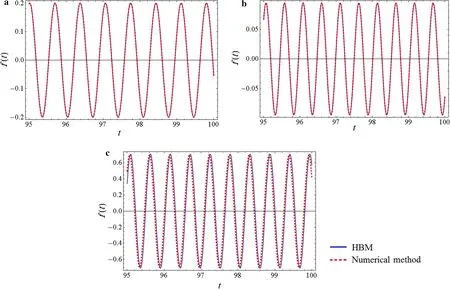
Fig.5 Comparison between the numerical solution and HBM for the highly nonlinear case.a Time-histories of the micro-plate's vibration in P=300 Pa and ωd=0.9 before resonance.b Time-histories of the micro-plate's vibration in P=300 Pa and ωd=1.2 after resonance.c Time-histories of the micro-plate's vibration in P=300 Pa and ωd =1.116 near to resonance
In each figure, time-histories have been plotted in three regions, before resonance, after resonance and near to the peak of resonance. In analytical plots in each definite frequency ωdEqs. (43) and (44) determine the amplitude A1and the phase φ.Then Eq.(24)gives the dynamic response of the system.It can be observed in Figs.3-5,that HBM is validated by the numerical solution.In Fig.3,the magnitude of the excitation is 100 Pa and as seen in the associated F-R curve in Fig.2,the jump-up phenomenon does not happen;therefore,this case is called semi-linear.The numerical solution verifies HBM in all three samples of the frequency ωd,completely.
Figure 4 is related to the case in which the magnitude of excitation is P =200 Pa. F-R curve in Fig. 2 shows that jump will occur in this case. But the hardening behavior is not large enough that upper branch and lower branch separate from each other completely.Therefore,this case can be called weakly nonlinear.Acceptable agreement between HBM and numerical method can be seen in all regions.
P=300 Pa in Fig.5,the nonlinearity of the system can be observed in F-R curves completely and in numerical solutionsupperbranchandlowerbrancharedifferent.Wecallthis case highly nonlinear. Figure 5 shows that before and after resonance,HBM is in an excellent agreement with the numerical method.For time-history response at the resonance,we selected ωd=1.116. In Fig. 5c, it can be seen that there is a little error in the results of the first-order analytical HBM(the phase and the amplitude are 2.0%and 1.6%larger than that in numerical solutions,respectively).
3.2 Effect of the voltage and Casimir force on the natural frequency
Because of the interaction of electromechanical coupling in the MEMS micro-plate,the natural frequency of the system is a function of the applied voltage. In Eq. (15), it can be observed that=10A and based on Eq. (21)=10A′.Since the first mode shape is used in the Galerkin method,ω1is the main frequency of the system.Figure 6 shows variations of the natural frequency versus the applied voltage.It is demonstrated that the natural frequency decreases with increasing the applied voltage on the plates and it reaches zero at pull-in voltage. Additionally, by decreasing the gap distance,the pull-in voltage decreases,whereas the intensity of the natural frequency increases.
There is no significant difference between 10A and 10A′except in the small gap distances.To see the effect of Casimir force clearly,the gap size must be reduced.Figure 7 shows the variety of the natural frequency versus to the voltage in smaller gap distances. Graphs have been plotted for a twosided micro-plate with a radius of 50 μm and a thickness of 0.5 μm. As it can be seen, by assuming Casimir effect,frequency decreases in all values of the applied voltage.

Fig.6 Influence of applied voltage on the main natural frequency in various gap distance

Fig.7 Influence of applied voltage on the main natural frequency of the system with assuming Casimir force (continues lines) and neglecting Casimir force(dashed lines)
3.3 Influence of voltage,damping,and thickness on F-R curves
Figures 8-10 indicate the effects of applied voltage,damping coefficient and plate thickness on the frequency response curves, respectively. In each case by using Eq. (44) and assuming the properties in Table 1,the F-R curve has been plotted and parametric study has been done.
As discussed previously,the applied voltage can decrease the main natural frequency.In this study,primary resonance is considered and resonance frequency is near to the natural frequency of the system.Therefore,as it is seen in Fig.8,with a constant 150 Pa external pressure, increasing the voltage shifts the resonance frequency to the left of the F-R curves.Furthermore, voltage can intensify the resonance point and brings the system closer to instability.As it can be observed in applied voltage 48 V, vibration amplitude of the microplate is larger than the gap distance(A1>1),which addresses dynamic pull-in instability in 150 Pa.It seems that this pull-in voltage can be reduced when the external pressure increase and there is a coupling between the electrical and external pressure in instability analysis that can be an interesting subject to future studies.

Fig.8 Influence of the variation of applied voltage on nonlinear F-R curves

Fig.9 Nonlinear F-R curves in various damping coefficients (in all cases,the magnitude of the excitation has been fixed at 300 Pa)
It is worth mentioning that according to Eq.(15)and coefficients B and C in Eq.(16),the applied voltage has a negative effect on 3rd and 5th order nonlinear terms,which means in high voltages,before instability,some softening(bending to left)behavior appears in the system.

Fig.10 Nonlinear F-R curves in various thicknesses of micro-plate h.Variation of the thickness changes the amplitude in all domains of the frequency and also alters the backbone curves
Figure 9 shows the sensitivity of the system to damping coefficient,which can be applied by squeezed film damping[1]. Increasing damping leads to the reduction of the resonance peak in F-R curves, insofar as it eliminates jump.In Fig. 9, the external force has been fixed to be 300 Pa.The backbone curve is the locus of the peak amplitudes in frequency response curve [35]. It is seen in Fig. 9 that the backbone curve passes through the all resonance points.
The thickness of the micro-plates in sensors is one of the most important parameter for design because it is effective in the mechanical sensitivity of the device[12,13].
F-Rcurvesinvariousthicknesses(aroundtoh=2.25μm)are observed in Fig.10.In all cases magnitude of the excitation has been fixed to be P =200 Pa. By decreasing the thickness, (1) the amplitude of the response increases in all frequency domain; (2) first natural frequency of the system decreases;(3)nonlinear hardening behavior is intensified. We can see in Eq. (7) that parameters α1, α2, and α3are inversely proportional to h.Therefore,by decreasing the thickness h, coefficients of the nonlinear terms A-F at Eq.(15)will be changed.Although it cannot be recognized which of the coefficients A-F neither increase nor decrease generally,but the final result is the growth of the hardening in the system.
As it is observed in Fig. 9, all the frequency response curves in various damping have the same backbone curve and by decreasing damping, hardening of the system will remain fixed,but in Fig.10,reduction of the thickness bends the backbone curve to the right and intensifies the hardening.
3.4 Force response curves and catastrophe surface
Multi-valued regions and jump phenomenon can also be observed in force response curves. By Eq. (44) and substituting properties from Table 1, force-response curves for a two-sided capacitive micro-plate have been plotted for various ωdand the result can be seen in Fig.11.

Fig.11 Force response curves in various ωd for two-sided capacitive micro-plate
In linear system, the response amplitude varies linearly with the external force at a certain frequency[41].In nonlinear system this relation is not only linear,but also,in some regions,is not a function.For ωd>1,Fig.11 indicates that by changing the magnitude of the excitation in a certain frequency,it is expected to see a jump in both lower and upper branches.
Another way to show the multivalued response regions in nonlinear vibration is plotting a catastrophe surface or a cusp[44,45].
Figure 12 shows the catastrophe surface for the two-sided capacitive micro-plate system.Based on Eq.(44),if we look at Eq.(44)as a relation of a mathematical surface such as A1=g(ωd,P),it can be plotted in a certain domain of ωdand P.From another point of view,this surface has been achieved by combining the F-R curves with force response curves and exhibits all possible amplitudes of the steady-state response.
3.5 Effect of Casimir force on F-R curves
Based on the results in Sect.3.2,Casimir force,similar to the voltage,rebates the natural frequency of the system.Casimir force will be more effective in tiny gap distances,where the size of the device is small. Based on the relation for α3in Eq.(7),Casimir force is inversely proportional to the fourth power of the gap distance.Therefore,to observe the Casimir effect,a smaller size of two-sided capacitive micro-plate has been considered in this investigation. For this purpose, by using Eqs. (37) and (44) (as the solutions of Eqs. (15) and(21),respectively),nonlinear F-R curves have been plotted in Fig. 13. These graphs have been obtained for a circular micro-plate by the radius of 50 μm and thickness of 0.5 μm.The applied voltage has been fixed on 1 V and magnitude of excitation is 5 Pa,for all the cases.Casimir force acts on nonlinear response similar to the electrostatic force. There is no observed tangible difference between F-R curves in Eqs. (37) and (44), where the gap is larger than 200 nm.Assuming the Casimir force in the mathematical model leads to smaller resonance frequency and larger softening behavior.

Fig.12 Catastrophe surface for the nonlinear two-sided capacitive micro-plate system

Fig.13 Influence of Casimir force on F-R curves in smaller gap distance.Casimir force emphasises the resonance frequency and amplifies the softening behavior
In this study, the essence is that the geometric nonlinearity is responsible for the hardening. On the other hand,the Casmir force is responsible for the softening. There is a competition here that can be noted in coefficients A-F in Eq.(16).
4 Conclusions
Nonlinear vibration of a circular micro-plate that is located between two rigid electrode plates was presented in this investigation by analytical solution. The micro-plate is under harmonic excitation load,two-sided electrostatic and two-sided Casimir forces. Geometric nonlinearity has been included in the mathematical model.The analytical solution was a combination of HBM and Galerkin methods and led to the closed-form.A nonlinear frequency response relation has been derived.HBM has been validated by the numerical solution for the primary resonance of the system.It has been demonstrated that the applied voltage reduces monotonality the natural frequency of the electromechanical system as far as it reaches to zero at pull-in voltage.Afterwards,by plotting the F-R curves,a comprehensive study was done to observe the effects of the various parameters on the response of the system.
Equation of motions in the presence and absence of Casimir force was obtained as nonlinear ODEs, which describe dynamics of the system. The nonlinear behavior is due to the combination of electromechanical-molecular interactions in a two-sided capacitive system.Casimir force similar to the applied voltage has tangible effects on the natural frequency,softening behavior and peak of the resonance in NEMS/MEMS with small sizes(for the studied case where the gap distance is smaller than 200 nm).
AcknowledgementsWe are deeply grateful to Prof.Jakob Søndergaard Jensen,who is chief of the Center for Acoustic-Mechanical Micro Systems(CAMM)in Technical University of Denmark(DTU),for his kind guidance and revisions that enriched the contents of this manuscript.

- Acta Mechanica Sinica的其它文章
- Instability inspection of parametric vibrating rectangular Mindlin plates lying on Winkler foundations under periodic loading of moving masses
- GRAPHIC ABSTRACT
- Mechanism of wavy vortex and sign laws in flow past a bluff body:vortex-induced vortex
- Study on vibration of dragon wash basin and free surface waves inside
- Spectral measurements of hypervelocity flow in an expansion tunnel
- Quasi-static simulation of droplet morphologies using a smoothed particle hydrodynamics multiphase model