
Numerical and experimental analysis of the closed-cell aluminium foam under low velocity impact using computerized tomography technique
2019-11-28 08:46TalebiSadighiAghdam
Acta Mechanica Sinica 2019年1期
S. Talebi·M. Sadighi·M. M. Aghdam
Abstract In the present work,the response of closed-cell aluminum foams under low-velocity impact has been studied numerically and experimentally. Computerized tomography is employed to access three-dimensional (3D)microstructure of the closed-cell aluminum foam. Effective parameters including foam density and the velocity of impactor on foam dynamic behavior are investigated. In order to show the validity and accuracy of results, some static experiments and low-velocity impact tests have been conducted. Results indicate a remarkable agreement between the simulation and experimental data. Moreover,the results show that by increasing the density of foam samples,the highest difference between numerical and experimental results for peak stress and absorbed energy are 35.9% and 6.9%, respectively, which is related to the highest density. For impact velocities ranging from 3.1 to 4.2 m/s,the maximum discrepancy in peak stress and absorbed energy occur at an impact velocity of 3.1 m/s in which corresponding errors are 33.3%and 6.6%,respectively.For the impact velocity of 40 m/s,the highest increase in peak stress and absorbed energy are 667.9%and 370.3%associated with the density of 0.5 and 0.3 g/cm3,respectively.
Keywords Finite element analysis·Impact·Aluminum foam·Experimental analysis·Energy absorption
1 Introduction
Closed-cell foams, a novel class of materials, are in most cases produced by trapping gas bubbles in a solid. However, metal foams have attracted great attention during the recent decades. On the other hand, metal foams are widely used in various engineering and industrial fields,such as bumpers, body implants, and sandwich structure core,due to their mechanical,thermal,and insulation properties. Metal foams are generally composed of aluminum;however, they can be produced by other metals such as steel, nickel, titanium, copper, and gold. Energy absorption of closed-cell metallic foams due to the vast plastic deformations in the failed cell walls is among the several properties that have created numerous applications,such as automobiles, trains, airplanes, and other vehicles[1-5].
The works of Dannemanna and Lankford[6]studied the compressive deformation of open-cell and closed-cell aluminum foams. Experiments have been performed with the loading rate in the range of 400-2500 per second by Hopkinson test. The effect of strain rate is dominant in the foam with higher relative density. Comparing the two types of open and closed-cell foam,closed-cell foams show a higher plateau stress than open-cell foams.Parameter studies on the amount of porosity and strain rate in the dynamical behavior of aluminum foam have been carried out by Liu et al.[7]. A foam model has been obtained using the imaging method.The effect of strain rate on the foam was remarkable for higher values of relative density. Moreover, the effect of air pressure on static stress and strain rate was negligible. The study by Montanini [8] investigated the effect of strain rate on energy absorption of aluminum foam. It has been shown that when the applied load increases,foam cells are crushed.Among the mechanisms of failure,plastic buckling, plastic yield and brittle crushing may be mentioned,which depend on the mechanical properties of the cell walls.In two foams with the same density, there is a possibility of different energy absorption, which is attributed to their microstructure. The experimental results demonstrate that the effect of strain rate for open-cell aluminum foams is negligible,whereas closed-cell aluminum foams are considerably sensitive to strain rate. Numerical investigation was carried out by Fang et al. [9] to study the influence of cell wall strength and the amount of porosity,which are effective in energy absorption values. The model presented in their study possesses the ability to consider different thicknesses for the cell walls.Furthermore,Li et al.[10]evaluated analytically the one-degree-of-freedom model of impact in order to estimate the amount of energy absorption of the metallic foam. To verify the results, a low velocity impact test has been carried out on aluminum foam samples. The results show acceptable amounts of energy absorption. Moreover,they concluded that the foam behavior in dynamic loading is similar to quasi-static loading.Furthermore,in the case that the velocity of impact is lower than a critical velocity, the shock wave induced by inertia is not observed.On the other hand, the compression strain rate increases when increasing the height of the impactor. Energy absorption occurs in closed-cell metal foams via various mechanisms such as bending, buckling and fracture of the cell walls. The work by Yun et al. [11] carried out two explosion experiments on panels composed of aluminum foam in order to evaluate their protection against explosion waves. The results show that use of aluminum foams reduces the pressure of explosion waves by a considerable amount and despite their light weight they can be used for the purpose of protection of the buildings against explosion waves.In their study,Wang et al. [12] carried out a series of experiments to study the effects of strain rate and inertia on the deformation behavior of closed-cell aluminum foam under impact loading.The experimentshavebeenperformedbyHopkinsontestinwhich it has been shown that reaching a homogeneous stress condition for thick foam samples is difficult and the resistance of the aluminum foam is sensitive to the strain rate.In order to validate three deformation modes (homogeneous mode,quick mode, shock mode), two different methods of direct impact have been used.The results indicate that stresses are increased in the front plane more than the end plane when the impact velocity is increased from 16 to 113 m/s.The effect of axial inertia at high velocities is higher than the effect of strain rate.
Computerized tomography,or CT scan,is a method used in numerous research and therapeutic applications in diagnostic science and medical physics. In this method, the human body or the sample under study is scanned layer by layer, and thus the internal parts of the human body or the sample are obtained. Because of the increasing quality of X-ray imaging and development in the processing of images,the applications of images obtained by CT scan have expanded. This method has many applications in obtaining a finite element model of parts,as well as reverse engineering and material sciences.The method also has considerable applications as a non-destructive inspection instrument in various fields such as aerospace for finding cracks and also electronics industries to evaluate the quality of connections.Furthermore, due to the quality and high precision of the method, some researchers have used this method to access the three-dimensional(3D)character of internal microstructure in metals [13-17]. The work of Elmoutaouakkil et al.[18]presented a two-dimensional(2D)and 3D modeling of metal foam Alporas, IFAM, and Norsk-Hydro using X-ray and image processing.In addition,Veyhl et al.[19]analyzed the finite element model for closed-cell and open-cell foams using CT imaging and obtained the elastic modulus in all three directions. They found a linear relationship between relative density of foams and their elastic moduli.The study by Miedzinska et al. [20] studied the microstructural properties of closed-cell aluminum foams experimentally and numerically. The researchers have employed CT to model the geometric structure of the samples,while the analysis is performed in LS-DYNA software. The results of this work indicate that by increasing the number of holes per inch from 10 to 40 ppi, the absorbed energy increases. In their work,Ramirez et al. [21] modeled the elastoplastic deformation behavior of open-cell aluminum foams under compressive loading and compared it with experimental results. They obtained 3D structure of the samples with micro-CT and utilized a 3D solid model for numerical analysis in LS-DYNA software. They also showed that the results of the compression test and 3D numerical solution are in satisfactory agreement with each other.An experimental and numerical study on closed-cell aluminum foam subjected to uniaxial compression was carried out by Saadatfar et al.[22].X-ray computed tomography has been used to visualize the 3D structure. The results showed that strain hardening occurs dominantly in regions with large cells and high anisotropy.The work of Kader et al. [23] studied the elastic-plastic behavior of shock wave propagation and pore collapse mechanisms of closed-cell aluminium foams.A micro-computed tomography-based foam geometry has been developed. A good correlation was found between experimental results and finite element predictions. The effect of velocity on deformation has been investigated.At low impact velocities,the free-surface velocity increased gradually. Investigation by Islam et al. [24] looked at the dynamic behavior of closed-cell aluminum foams. The elastic-plastic pore collapse mechanism has been investigated using digital image correlation (DIC) and micro-computed X-ray tomography.The results showed a significant increase in elastic and plastic strength during the pulse loading.The mechanical response of porous structures made with the different unit cells have been studied analytically, numerically, and experimentally[25,26].

Fig.1 Closed-cell aluminum foam samples with different densities: low density (0.2 g/cm3), medium density (0.3 g/cm3), and high density(0.5 g/cm3)
In previous studies,micro-CT imaging technique has been used to access the internal microstructure of the foam samples. Micro-CT imaging considers more details compared to simulation requirements,and to cover the details,smaller mesh size is required, which leads to a very high solving time. It will be then very difficult to use more cells for numerical analysis. Moreover, there is also no straightforward access to the micro-CT device.The technique used in this study needs a common CT scan device used in medical science. This method is more optimal and has better accuracy and less solution time,as well as better convergence.In the present work,closed-cell aluminum foam behavior under impact loading is studied.Impact load is of the low velocity type created by drop test setup.The foam behavior is investigated based on both experimental and numerical analyses and the results are compared with each other. Moreover, a parameter study on the impact velocity as well as foam density is performed.
2 Experimental method
2.1 Closed-cell aluminum foam fabrication
Aluminum foam is manufactured by a casting process,which consists of several steps including thickening,foaming,and cooling.Aluminum is initially heated up to about 660°C and TiH2powder is then added in the molten state such that the TiH2powder is decomposed into titanium and hydrogen gas.Hydrogen gas causes the creation of bubbles within the melt.In order to stabilize the bubbles, calcium was used, which increases viscosity. When the melt is formed to create the structure of the foam,the melt is cooled.Care must be taken since due to the density difference, the created bubbles by TiH2move upward. This in turn necessitates the different density of the foam block at different heights in the foaming direction.In this regard,the foam block may be divided into three distinct regions oflow,moderate and high density.Figure 1 shows the foam samples classification based on the density. As seen in this figure, a higher density foam has a thicker wall cell.In the next step,from each of the sections,samples with approximate dimensions of 40 mm×40 mm×40 mm are produced. The exact values of dimensions and density of each sample are tabulated in Table 1.
2.2 Drop weight impact test
An impact test is performed to examine the performance of metallic foams.The test was conducted using a low-velocity drop test setup.The device consists of a metal frame with a height of approximately 3 m, an impactor holder plate and chains to adjust the height of the impactor,extra weights,an accelerationsensor,andadataacquisitionsystem.Toconduct the experiment, the sample is first positioned at the speci-fied location of the setup.Weights are placed depending on the type of experiment, adjusting the height of the setup as needed to obtain the required energy. Data capture is performed by the acceleration sensor, and data are transferred through electronic set embedded in the setup to the nearby computer.Because of the high volume of data,the data transfer for each sample takes about 10 min.Figure 2 shows the drop weight impact test setup.

Table 1 Closed-cell aluminum foam samples specification
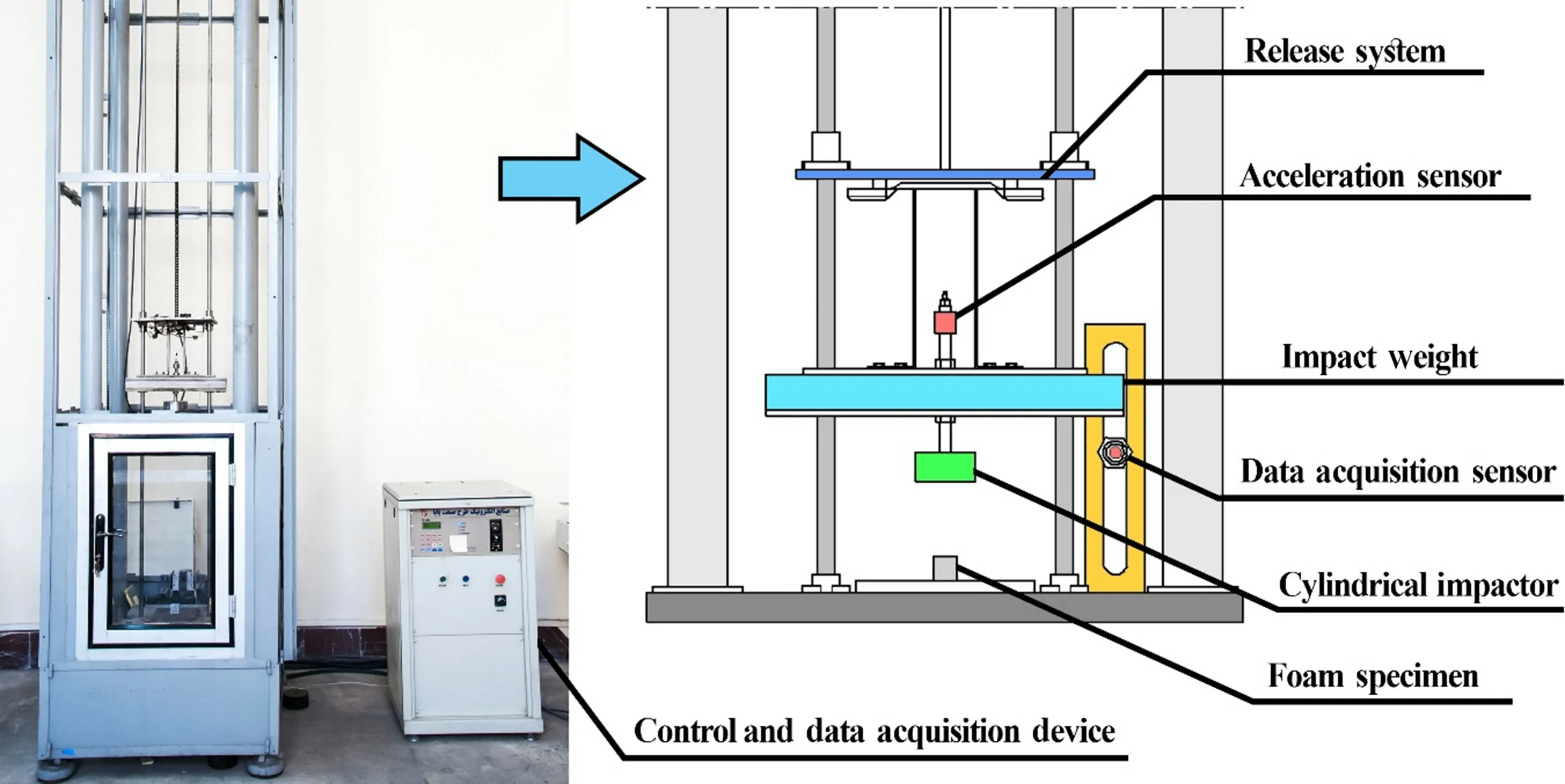
Fig.2 Drop weight low-velocity impact test setup
3 Numerical simulation method
Initially, the structure model of foam samples is required to analyze the foam behavior under impact loading. The model is then incorporated into LS-DYNA software.Regarding the complex structure of metallic foams, conventional techniques are not capable of modelling foam microstructures.The CT method is,therefore,adopted to determine the complex geometric structure of this type of foam.To achieve this objective,the samples were placed in the multi-slice CT machine and imaging of those samples were performed.The CT scan device outputs two-dimensional images of different sections of the foam,which should be connected to each other in an appropriate way.To this end,the software Mimics was used for obtaining 3D model of the foam.Accordingly,the surrounding surface is first created by point cloud. The point cloud in turn is utilized to extract 3D discretized model of foam samples.Figure 3 illustrates the complete procedure of modeling aluminum foam microstructure including CT scanning,extracting 2D images out of the CT machine and also the reconstruction of 3D model in the software Mimics.
In order to analyze the nonlinear behavior of aluminum foams under intense dynamic loadings precisely,the PLASTIC KINEMATIC model, material type 3 in LS-DYNA, is employed to simulate the cell-walls, aluminum alloy. This model is suitable to model isotropic and kinematic hardening plasticity with the option of including rate effects.Standard computational parameters are as follows:mass density ρ =2.7 g/cm3, Young's modulus E =70 GPa, Poisson's ratio ν =0.3.On the other hand,PLASTIC KINEMATIC model also requires yield stress,as well as tangent modulus as input parameters.In this regard,a uniaxial tension static test was performed and the following numerical values of required parameters are extracted:yield stress SIGY =150 MPa,tangent modulus ETAN =1.724 GPa. Figure 4 illustrates the procedure of such an extraction.
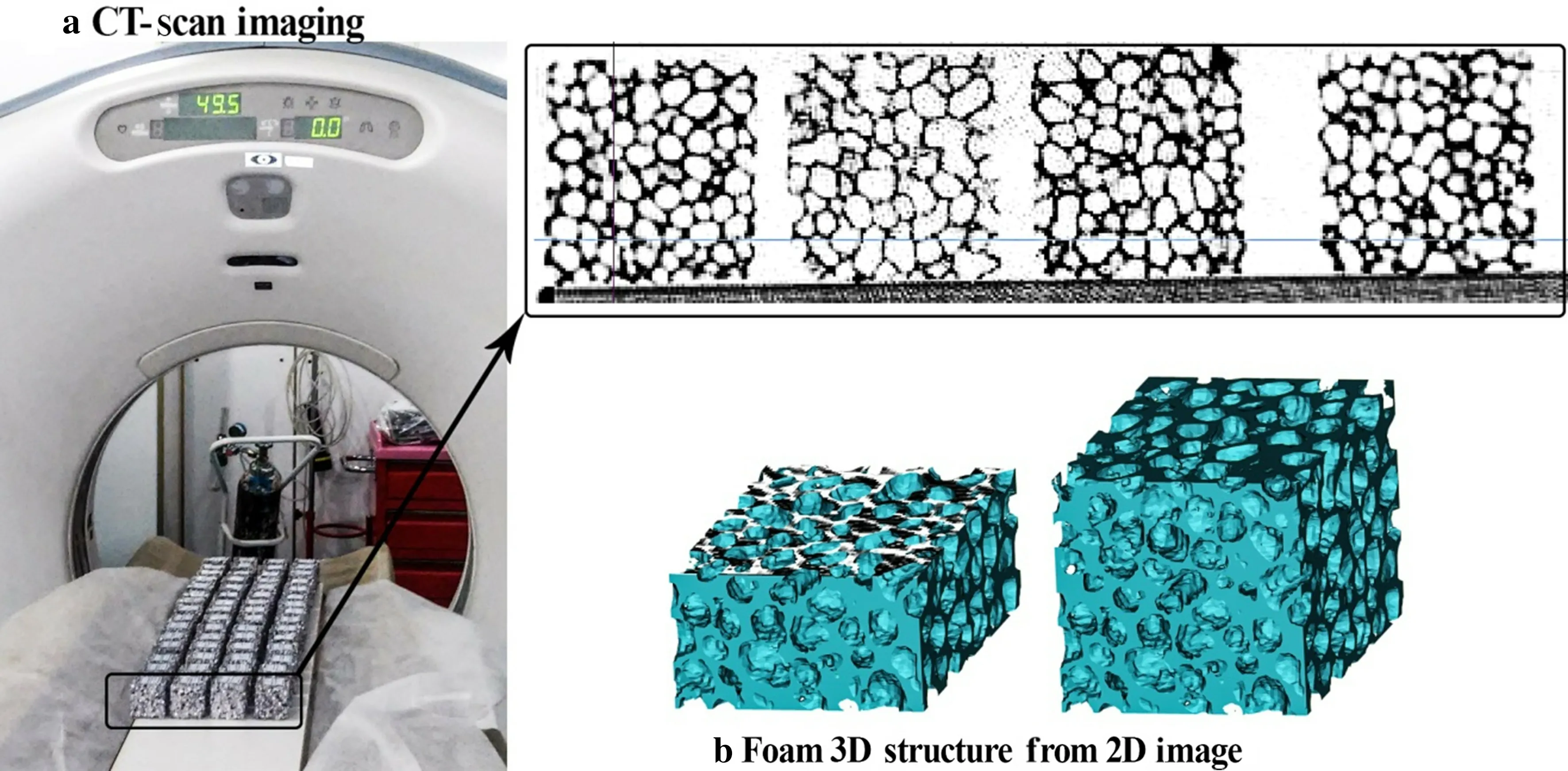
Fig.3 CT imaging and 3D modeling of the samples of closed-cell aluminum foam

Fig.4 Aluminum uniaxial static tensile testing result
In order to incorporate the strain rate sensitivity of the base material,the well-known Cowper-Symonds relation

is employed for the plastic deformation of the base material in the adopted 3D model in which C and P are the Cowper-Symonds coefficients, ˙ε is the strain-rate, σyis the dynamic stress or strength,and σ0is the quasi-static stress or strength.Aluminum alloys generally manifest weak rate dependency.The Cowper-Symonds parameters for aluminum alloys are considered to be C=6500 and P=4[27].The steel impactor and bottom plate are treated as rigid body in the model.The corresponding material parameters are: mass density ρ =7.8 g/cm3,Young's modulus E=200 GPa,Poisson's ratio ν=0.3.
In order to solve the governing equations over the foam region using the finite element method, solid pyramid element in the software is adopted.The number of elements for foam samples is typically on the order of one million.Care must be taken that the mesh size is limited by a lower bound due to the discrete scanning sections.The element size for the present foam samples are typically considered to be 0.5 mm.On the other hand,the bottom plate along with the impactor plate is meshed by solid cube element.
Togetclosertotherealconditionsofloadingandboundary conditions in impact test,the foam sample is placed between a rigid fixed plate and a cylindrical rigid impactor and the initial velocity was attributed base on the initial velocity of the impactor in drop test experiment,as shown in Fig.5.The contact constraint is of the type automatic single surface for closed-cell foam sample,and the contact between impactor and the fixed base with foam is selected as automatic surface to surface.
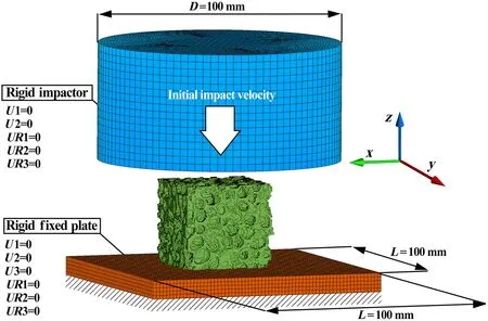
Fig.5 Loading and boundary conditions of finite element modeling of closed-cell aluminum foam

Fig.6 Uniaxial quasi-static compression test
4 Results and discussion
4.1 Experimental results
To indicate the accuracy and verification of the results obtained from numerical analysis, the results of the experimental impact test on the closed-cell aluminum foam are compared with the similar results from finite element analysis. These experiments include three impact tests with low velocity for three different foam densities. Before low velocity impact test,three compressive static tests for three different foam densities are conducted in order to evaluate overall behavior,energy absorption and densification strain of the closed-cell aluminum foam samples.The procedure of performing static tests is shown in Fig.6.The results of these tests can be seen in Fig.7 in which the static pressure test has been conducted for three foam samples of densities 0.2,0.3,and 0.5 g/cm3.Numerical integration of the curves in Fig.7 by the trapezoidal method estimates the energy absorption during a 50% deformation. Consequently, by selecting the mass of impactor,its initial velocity is readily estimated.As expected, Fig. 7 states that by increasing density, the area under the curve increases and consequently the amount of energy absorption increases.Because of increased noise for impact elevations of more than 1 m,three different impactor heights including 50, 70, and 90 cm are considered. Using prepared impact weights,the impact mass of 14 kg is considered. The selection of the impactor mass and height values is because the impact energy is sufficient to destroy the sample.For the impact parameters considered,the impact energy value is about 1500 kJ/m3,which is sufficient to destroy all three types of foam density. Each test was repeated three times to ensure the accuracy of the experimental results.

Fig.7 The results of uniaxial quasi-static compression test for three different foam densities
In order to analyze the effect of the low velocity impact on the foam,a few experimental tests are first conducted and these results are compared with the results of the numerical method. Figure 8 indicates different configurations of the foam sample during the impact procedure.As seen,the impactor is released from a specified height and impacts the aluminum foam sample. As a result of the strike, plastic deformation and fracture is created in the foam, which causes absorption of the energy of the impactor.It is observed that with the initiation of impact,the plastic deformation of the foam increases and finally dense foam is produced.The amount of the energy absorption depends on the velocity of the impactor and the density of the foam.Therefore,the two factors are effective parameters in impact response, which are analyzed herein.
4.2 Numerical results
Figure 9 shows the deformation and failure of the foam specimen at three different moments for impact velocity of 3.7,10,and 20 m/s.There are two important points in how the foam samples are deformed at different speeds. The first point is the cell failure start region,which for an impact velocity of 3.7 m/s starts from top and bottom at the same time,and the rate of progression of cell failure is higher at the top of foam specimen,which corresponds to the cell failure pattern in the experimental test. The second point is how the cells break down and the dominant mode of cell collapse.Because the main material of the cells is pure aluminum,considering the percentage of elements found in the foam structure used in the experimental test,it has a brittle structure,and the dominant fashion in the collapse of cells is brittle fracture.This is also evident in the oscillatory nature of the stress strain graphs in the impact test.
Figure 10 shows the effect of density on the impact response at a constant velocity of 3.7 m/s.This figure states that the curves obtained from the experimental test is in good agreement with the results of the finite element solutions.Evaluating the numerical and experimental results one may conclude that in a constant velocity with increasing density the peak stress will increase. Figure 10 also indicates that the numerical method slightly overestimates the results.The next study is devoted to the effect of velocity on the impact response.The density of samples in tests related to this analysis is constant and is considered 0.2 g/cm3.Figure 11 reveals that similar to the previous results, the finite element solutions show good match to the experimental data and hence it may be concluded that the solution obtained from the numerical solution has a good reliability.As expected,it is observed that the peak stress increases with increasing impactor velocity.

Fig.8 Numerical and experimental low velocity impact test procedure:a low velocity impact test setup,b-d foam specimen crushing,e-g numerical simulation oflow velocity impact
4.3 Experimental test versus numerical results
Comparison of numerical results and experimental tests for maximum stress and energy absorption for three different foam densities under low-velocity impact at constant impact velocity (3.7 m/s) are shown in Fig. 12. As can be seen,the difference between numerical and experimental results for maximum stress increases with increasing density,which varies from 28.4%to 35.9%,and the smallest difference is in the average density.The difference in numerical and experimental values is much lower in energy absorption and did not show significant growth with a change in density.Considering that the maximum stress is a basic parameter in design and in order to transfer the lower force to the base of the installation site, we must have the lowest maximum stress,hence, at low speeds, the use oflow density foam reduces the force as well as the absorption of energy, and the use of high-density foam does not contribute to the absorption of energy and increases the amount of force applied to the system.
In Fig.13,the results of the experimental test and numerical analysis for three different impact velocities in constant foam density are shown.By increasing impact velocity from 3.1 to 4.2 m/s(three different impactor heights of 50,70,and 90 cm), the difference of numerical and experimental tests decreased from 33.3%to 25.6%,and the difference in energy absorption by increasing impact velocity,decreased.Because of the proper accuracy of numerical solution with increasing speed of impact,as well as the speed limit of the impact test,higher impact velocities were found numerically;one example is shown in Fig.14 for the impact velocity of 10 m/s for three different foam densities.It is obvious that with increasing impact velocity, maximum stress and absorbed energy has increased.

Fig.10 Experimental and numerical results related to low velocity impact test for three different densities:a 0.2 g/cm3,b 0.3 g/cm3,and c 0.5 g/cm3
Results are depicted in Figs. 15 and 16. The effects of increasing impact velocity(from 3.7 to 40 m/s)for the maximum stress are shown in Fig. 15. The effect of increasing the speed on the increase in maximum stress has been much higher than the density effect.For impact velocity of 10 m/s,by increasing the density, peak stress and energy absorption is increased from 31.7%to 77.3%and 43.5%to 56.6%,respectively.This trend is observed for higher impact velocities which demonstrate the greater effect of increasing the density on the peak stress. On the other hand, at a constant density,for example,at low densities,increasing impact velocity from 10 m/s to 40 m/s,the maximum stress increased from 31.7%to 660.6%,while the absorbed energy increased from 43.5% to 334.2%. This process has also been more intense for higher densities.This case also shows the greater effect of increasing the impact velocity on the peak stress versus absorbed energy.Considering that in designing structures that have an energy absorption function, the energy absorption and maximum stress of the system are the most important design parameters, one of the main goals is to reduce the amount of force and thus the stresses on the system. Therefore, at higher speeds, it can be concluded that using lower density foams in terms of energy absorption and the maximum amount of stress applied to the system is more suitable.
5 Conclusion
In this study, the low-velocity impact on closed-cell aluminum foams is studied numerically and experimentally.In order to assess 3D microstructure of closed-cell aluminum foams, computerized tomography is employed. The results are mentioned in the following:
1. 3D model of the aluminum foam microstructure is created via computerized tomography and the model is analyzed under low-velocity impact test.
2. The results of the finite element method are compared with the experimental data and it is concluded that the numerical method is an optimized and accurate method.
3. The effect of two very important parameters including the velocity of impactor and foam density on the impact response is investigated.The results show that at a constant velocity, an increase in foam density leads to the increase in peak stress,but has no remarkable influence on the energy absorption.It is also observed that with the increase in velocity of the impactor,both peak stress and energy absorption increase considerably.

Fig.11 Experimental and numerical results related to low velocity impact test at three different impact velocities:a 3.1 m/s,b 3.7 m/s,and c 4.2 m/s

Fig.12 Comparison of experimental and numerical results related to impact test of velocity 3.7 m/s for three different foam densities:a peak stress,b energy absorption
4. Impact velocity produces a great effect on peak stress and less effect on absorbed energy.
5. By increasing foam density, the difference between numerical and experimental results for peak stress are found to be increased from 28.4% to 35.9%, whereas energy absorption values do not show significant growth.
6. By increasing impact velocity from 3.1 to 4.2 m/s,the difference between numerical and experimental results are found to be decreased from 33.3%to 25.6%and 6.6%to 3.1%for peak stress and energy absorption,respectively.

Fig.13 Comparison of experimental and numerical results related to the low-velocity impact test on foam samples of density 0.2 g/cm3 for three different velocities:a peak stress,b energy absorption

Fig.14 Stress strain diagram of higher impact velocity (V =10 m/s)for three different foam densities

Fig.15 The effect of impact velocity on peak stress of closed-cell aluminum foam for three different foam densities

Fig.16 The effect of impact velocity on energy absorption of closedcell aluminum foam for three different foam densities
7. For impact velocity of 10 m/s,by increasing foam density from 0.2 to 0.5 g/cm3,peak stress and energy absorption arefoundtobeincreasedfrom31.7%to77.3%and43.5%to 56.6%,respectively,which shows the greater effect of increasing the impact velocity on the peak stress,and this trend is also observed for higher impact velocities.

- Acta Mechanica Sinica的其它文章
- Instability inspection of parametric vibrating rectangular Mindlin plates lying on Winkler foundations under periodic loading of moving masses
- GRAPHIC ABSTRACT
- Mechanism of wavy vortex and sign laws in flow past a bluff body:vortex-induced vortex
- Study on vibration of dragon wash basin and free surface waves inside
- Spectral measurements of hypervelocity flow in an expansion tunnel
- Quasi-static simulation of droplet morphologies using a smoothed particle hydrodynamics multiphase model